


Tractorman
Yearly Subscription
-
Joined
-
Last visited
Everything posted by Tractorman
-
I am very interested to hear the final outcome - what the actual problem is. - John Did you make any valve adjustments, or did you just check them? Just trying to rule out any other potential cause. - John
-
My brother-in-law has 2003, manual 6 spd. I will have to check his truck for the high idle feature. Thank you, - John
-
@Lund1990, what year is your truck? Also, automatic or stick? - John
-
No chance of that. Those remaining injectors bled themselves of air long before you even pulled out of the driveway. - John
-
Just out of curiosity, do you feel the slight flutter, with transmission in "Drive" at idle, or in "Park" at idle? - John
-
Could be related to your 150 hp injectors and the symptoms just showed up with your newly installed VP44. Maybe nothing to worry about? - John
-
From what I understand, there are no inputs at idle - the ECM takes over. When the throttle is returned to idle, the "idle validation switch" takes over in the APPS sensor which switches to ECM only to control idle. So, I don't think any sensors (good or bad) on the engine would be recognized by the ECM at idle. Is it just the tachometer fluctuating, or do you hear the idle fluctuate, as well? - John
-
I bet it felt good to hear that engine fire up and run like it is supposed to, especially after working on it until midnight to get it done.. Good job! - John
-
Just a followup. Jim's Drive Train Specialties finished the repair on my truck on two days ago. Jim's crew installed a Dana 80 differential overhaul kit which included axle shaft bearings, pinion bearing and pinion seal. He said that visually the ring and pinion gear looked to be in very good condition. However, after setting up the gears and checking the pattern, he said the pattern was where in should be, but there was some wear on the ring gear. He said that it would not be a problem, but it will be noisy - just not as noisy as it was before the repair. It turned out not to be noisy at all - quiet under all operating speeds on the 150 mile trip home. I am very pleased with the service from Jim's Drive Train Specialties. If anyone is needing drive train or axle work done in the Boise, Idaho area, I highly recommend these folks. - John
-
@daav544, here is a tire size comparison for the tire you currently have and the future tires you will install later. Below is a sample of how these different tires sizes will have a minor effect on road speed and engine torque put to the ground. The first chart reflects your bald 215/85 R16 tires (30.4" diameter) The second chart reflects the tire you are going to purchase - 235/85 R16 (31.7" diameter) The numbers high-lighted in yellow represent the direct gear (1:1 ratio) for each transmission. I can change the numbers in blue to reflect different engine rpms, different axle ratios, and different tire sizes. - John
.thumb.GIF.886eed839180e9db501410247d584b92.GIF)
.GIF.390907211532d81fa5c9a7d0c425db0b.GIF)
.GIF.51df9a8d69a2b9d5cf0ea01abbd444ed.GIF)
-
I believe you are correct. A 245/75 R16 tire is about 30.5" inches in diameter (30.5 x 3.14 equal 95.77 inches in circumference). This is more of a perception or a "feels like" ratio comparison. I have never seen or heard of a good explanation regarding this comparison, but I think it has validity. Here is what it means to me. I am apologizing ahead of time if it gets too confusing. A lot of people believe that the 3.73:1 axle (beginning in the 3rd generation trucks) was the best axle ratio for towing performance when equipped with the stock 265/70 R17 tires and wheels. I tend to agree, it fits right in the middle of a 3.54:1 and a 4.10:1. * The 265/70 R17 tire is 31.6" diameter (3rd generation) * The 265/75 R16 tire is 31.6" diameter (2nd generation stock tire installed on later 2nd generation trucks) * The 245/75 R16 tire is 30.5" diameter (2nd generation specified on driver side door jamb) From this point on, the only way to fairly demonstrate how tire size affects different axle ratio comparisons is to find a gear that is common in all transmissions for the 2nd generation trucks and the early 3rd generation trucks. This common gear is a direct gear in which the engine rpm (transmission input shaft) and the transmission output shaft rpm are equal. The direct gear is different in different transmissions as shown below: * NV4500 - 4th is direct gear * NV5600 - 5th is direct gear * 47RH, 47RE, 48RE - 3rd with converter locked is direct gear Note that when comparing with automatic transmissions, the converter must always be locked. From this point forward it will be assumed that all axle ratio comparisons or tire size ratio comparisons or transmission comparisons will be in direct gear without mentioning the word "direct gear". So, back to the tire size and axle ratio comparisons. The standard to shoot for is the 265/70 R17 tire (31.6" dia) with a 3.73 axle on a 3rd generation truck. It turns out that the 265/75 R16 tire on the second generation truck is also 31.6" dia, but with a 3.54 axle. So, knowing that the tire diameter is the same for both trucks, the 3.73 axle will put more engine torque to the ground than the 3.54 axle. So, what if we put a 245/75 R16 tire (30.5" dia) on the 2nd generation truck? The smaller diameter will make the 3.54 axle "feel like" it is performing like a 3.69 axle - just like @Mopar1973Mansays. That's all folks. - John
-
Oregon Fuel Injection sounds like a good option. You may want to check out Diesel Fuel Injection Services in Portland. I have never purchased a VP44 injection pump from them, but I have done other business with them and I was treated well (also, a little closer to you than Eugene). You can request an email quote from their website. Diesel Fuel Injection Services 8922 NE Vancouver Way Portland, OR 97211 Phone: (503) 235-1947 - John
-
It hard to say which vendor has the best price. For example, Thoroughbred Diesel sells a re-manufactured VP44 with the latest updates on internal parts and the pump is run for 4 hours on a test stand, but the PSG is re-manufactured. The VP44 has a one-year warranty and sells for $1,100. Thoroughbred Diesel also sells a re-manufactured VP44 with the same updates and testing, but the PSG is new. The VP44 has a two-year warranty and sells for $1,450. My recommendation is to make sure the re-manufactured VP44 is run and calibrated on a test stand and that the PSG is new. - John
-
Yes. I recommend getting the tuner entirely out of the picture. I would then drive the truck for several days to see if the code returns. If it does, then you know you have a problem with the VP44. The P2016 code just means that a timing command has not been met and the engine goes to a derated power level. It could be a mechanical failure with the timing piston inside the VP44 as well as an electronic failure in the PSG. But, at this point it won't really matter. - John
-
Thanks for being honest, but you could scare away some newcomers to the site. - John
-
I had looked at that very same spreader and a suitable bearing press tool as well. I have decided to go with Jim's Drive Train Specialties in Boise. I have already spoken with Jim and hopefully just new pinion bearings and a seal will fix the problem. If more parts are needed (along with the technical skills to replace them), then at least the truck won't be sitting disabled in my shop with me scratching my head. @IBMobile, thank you for the information you provided. - John
-
Thank you for the great detail. Just for clarity, I was asking about the weight of the differential carrier, not the axle housing. Since I have never done this before, I was wondering how difficult it would be for one person to lift and guide the differential carrier into place from a creeper on the floor. I appreciate your information. - John
-
Thanks for the information. How heavy is the differential? I don't have a lift, so I would have handle the weight from underneath. It would seem that much weight could be awkward to handle. Just not sure I would want to take on the task, especially if I found other worn parts. I talked to the owner of Jim's Drive Train Specialties in Boise. He gave a ball park figure of $1200 - $1400 to R&R the pinion shaft bearings (including parts) as long as everything else is okay. - John
-
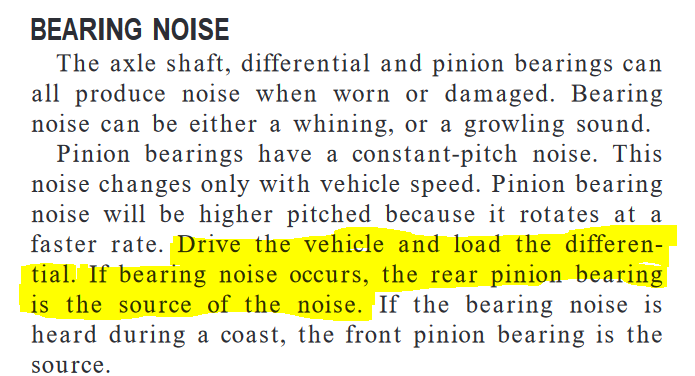
I have been experiencing a rear axle noise when driving. The noise occurs only under acceleration (light or heavy). It is a steady whine that changes in pitch with vehicle speed. The noise has become more prominent over the last several months. I disconnected the driveshaft and I can move the pinion shaft by hand up and down and side to side a small distance. My understanding is that there should be no free play here. I also removed the differential cover and drained the oil. There was the normal amount of fine filings on the magnet, but there were no chunks or pieces of metal in the bottom of the housing - in fact, it was very clean for the miles (386,000 miles). The ring gear shows a normal wear pattern and the teeth surfaces do not appear to be worn. According to the FSM: I am inclined to believe that I do have a worn rear pinion bearing because of the pinion shaft movement and the symptoms match the FSM description. The knowledge (and tools) needed are far beyond my skills for a differential repair on the Dana 80 axle. Can anyone recommend a competent differential repair shop in the Boise, Idaho area? Any thoughts or suggestions are welcome. - John
-
I would suspect it was there for a lift pump fuel pressure test port or for an in-cab lift pump fuel pressure gauge / warning light system. - John
-
At first, I was questioning your application method here. Then I went to the Permatex site to read how to apply the grey gasket maker and learned that you applied it exactly as instructed. For me, another thing learned today. - John
-
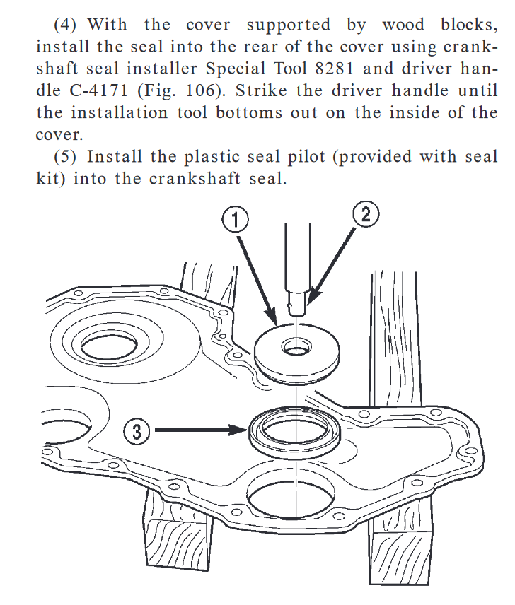
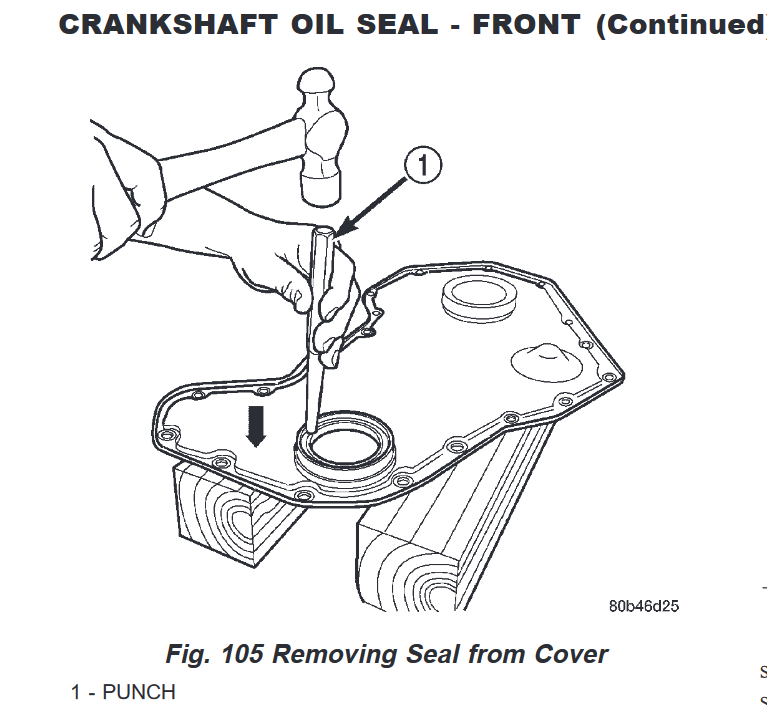
Not according the FSM...., Installation - Removal - (16) Support the cover on a flat work surface with wooden blocks (Fig. 105), and using a suitable punch and hammer, drive the old seal out of the cover from the outside of the cover (Fig. 105). It is probably not crucial to remove and install the seal according to the FSM, but there could be a reason for doing it this way. I used a sleeve and installed the sleeve and seal with the correct sleeve installer tool and seal installer tool. I have yet to see if there are leaks as I have not run the engine yet. - John
-
That is a PTFE seal and it sounds like you installed it correctly. I am not sure if slipping in a standard seal size sleeve will stop the leak, but I can see how it may be worth a try. From my understanding of how a PTFE seal works, there is a frictional bond that occurs where the two dry mating surfaces meet on initial shaft rotation, before engine oil contacts the surface. It is that action that seals the seal. Hopefully, installing a sleeve will work for you. Let us know what the results are. - John
-
Just double checking here. Was the new seal a PTFE seal? Was it installed dry (as it should be)? Interesting coincidence - I just installed one yesterday. - John
-
I assume you talking about the driveshaft from the transfer case to the front axle. Has that driveshaft failed in some way? If not, I recommend re-installing the driveshaft and don't worry about it. Two weeks ago I pulled my non-serviceable front drive shaft for inspection. All joints were working smoothly. I re-installed it. It has logged over 380,000 miles. I used to be a believer that non-serviceable u-joints had shorter life spans, and maybe they did 30 years ago. Since then, I have learned that there is a lot more that goes into an OEM non-serviceable u-joint - mainly the triple lip seals that keep the grease in, and the dirt and moisture out. - John


.GIF.f676db94136835bb21056284e3add5bd.GIF)
