Jump to content
  • Welcome To Mopar1973Man.Com LLC

    We are a privately owned support forum for the Dodge Ram Cummins Diesels. All information is free to read for everyone. To interact or ask questions you must have a subscription plan to enable all other features beyond reading. Please go over to the Subscription Page and pick out a plan that fits you best. At any time you wish to cancel the subscription please go back over to the Subscription Page and hit the Cancel button and your subscription will be stopped. All subscriptions are auto-renewing. 

Homemade Arduino VP44 & ECM project update #3


Recommended Posts

So I've made some real progress the last couple weeks. Truck runs pretty well and cold starts are much better now.

Still have to harden the hardware to make it a daily driver. I got some open source schematic and PCB CAD generator

program called KiCAD, seems to work pretty good. Had some install issues because I'm still using Win 7 LOL but I found an older version that 

works. I used to use Eagle CAD, not easy if you don't use it often and forget things like me.


Got most of the sanity checks done and correlated with the usual DTC codes. Some took  guess work there isn't much in depth

documentation on them. Thanks to the MoparMan forum I found most of what I needed. Thats the way things are getting Manufactures

keep a lot of secrets so they can keep the customer coming back to the dealership.


Most of the DTCs I included are VP44 side. Others are combined now. Example the crank sensor goes straight into my controller so skips a seperate

ECU.


I'm running out A to D channels for more sensors so I'm considering a seperate board to read all the other sensors, control the grid heaters

and lift pump and interface with the instument cluster and PCM. That may actually end up being where the Tunes are stored too. I can even 

fool the TPS output signal to the PCM so that could be some interresting transmission tinkering. I might even be able to take control of the

overhead display unit for even more fun. 


Code needs more work to handle multiple DTC's at once and store them so they can be read after powered down.


Code snip explains most of it. 

void sanityCheck(void)
{
  //Some original OBDII codes are no longer applicable with the new controller
  //0230, 0232, TODO DTC 1285
  static int errCnt1, errCnt2;
  static int DTCpending;
  static uint32_t lastSanity_time;
  if (millis() - lastSanity_time > 500)
  {
    lastSanity_time = millis();

    if (TPSv < 0.25)
    {
      DTCpending = 0122; //APPS voltage to Low
      errCnt1 += 2;
    }
    if (TPSv > 4.0)
    {
      DTCpending = 0123; //APPS voltage to High
      errCnt1 += 2;
    }    
    if (TPSv > 1.5 && idle_valid)
    {
      DTCpending = 0121;  //P0121 APPS Sensor Volts Do Not Agree Idle Validation Signal
      errCnt1 += 1;
    }
    if (BATv > 18.0)
    {
      DTCpending = 0563;    //Battery voltage too High
      errCnt1 += 1;
    }
    if (BATv < 3.0) {
      DTCpending = 0215;   //No voltage from fuel system relay / fuse
      errCnt1 += 1;
    }
    if (amps_ref1 > 2000) //raw ADC reading
    {
      DTCpending = 0251;       //P0251 VP44 Pump Fuel Valve Feedback Circuit Fuel valve current detected when there sould be none
      errCnt1 += 3;
    }
    if (AMPS < 2.0 && crank && BATv > 11.0 )
    {
      DTCpending = 0253;    //P0253 Fuel Injection Pump Fuel Valve Open Circuit
      errCnt1 += 1;
    }    
    if (AMPS > 15.0 && RPM > 800)
    {
      DTCpending = 0254;     //P0254 VP44 Fuel Valve Current Too High
      errCnt1 += 2;
    }
    if (TimingRetrys > 5) {
      DTC = 0216;            //actual timing not match commanded timing, >= 2 degrees mismatch and 5 re-try.
      TimingRetrys = 0;      //comes from TCV servo function 
    }
    if (MAPv < 0.1) {
      DTCpending = 0237;    //MAP sensor too low
      errCnt1 += 1;
    }
    if (BOOST > 5 && RPM < 900 && Load < 10 ) {
      DTCpending = 238;    // MAP sensor too high when it sould be low.
      errCnt1 += 1;
    }
    if (injMalfunction > 1) {
      DTCpending = 1688;    //injection drive malfunction, inj. event counter incorect.
      errCnt1 += 1;
    }
    if (errCnt1 > 3) {
      DTC = DTCpending;   //a pending error happend too many times, pending code becomes in effect
      errCnt1 = 0;
      DTCpending = 0;
      injMalfunction = 0;
    }

    if (!DTCpending) {
      errCnt1 = 0;    //happy
    }
    //pulsing sensors checked every 0.5 seconds, is engine rotating?
    if (VPsync || CKPsync || CamSync)
    {
      errCnt2 ++;     //errCnt2 increments fast or slow based on priority
      if (VPsync && !CKPsync && errCnt2 > 1) {
        DTC = 0336;   //P0336 Crankshaft Position Sensor Signal
      }
      if (VPsync && !CamSync && errCnt2 > 1) {
        DTC = 0341;   //P0341 Camshaft Position Sensor Signal Missing
      }
      if (CKPsync && !VPsync && errCnt2 > 1) {
        DTC = 0370;   //P0370 VP44 Speed/Position Sensor Signal Lost
      }
      if (VPsync && CKPsync && CamSync) {
        errCnt2 = 0; //rotation sensors are happy so reset error counter
      }
    }

    if (!eepromValid) {
      DTC = 1691;         //P1691 VP44 Controller Calibration Error.
    }
    if (WasIWDreset) {
      DTC = 1688;          //prog crashed and internal watchdog reset CPU; P1688 Internal Fuel Injection Pump Failure
    }

    if (DTC == 0122 || DTC == 0123 || DTC == 0216 || DTC == 238 || DTC == 0336) { //run but power limited
      if (RPM > 800 && RevCounter > 60) {  //some stabalizing time (60 crankshaft revolutions) to prevent false limp when started
        Limp = 1;                           //limp does not clear until ignition recycled, TODO
      }
    }
    if (DTC == 0563 || DTC == 0251 || DTC == 0254) { //critical errors shut off fuel system relay or risk burning inj. solenoid
      shutOff();
    }
  }
}//sanity done

void shutOff(void)
{
  TIM2->CCMR1 = FORCE_LOW;   //FORCE low to drive inj sol off
  pinMode(PC12, OUTPUT);      // Fuel system relay drive; end high Z state which allows hardware timeout and force off by software
  digitalWrite(PC12, LOW);   // Turn off Fuel system relay. may already be off by hardware fault detection circuit
  Serial.print(" shut off DTC ");
  Serial.println(DTC);        //show why it shut off
}


  • Like 3
Link to comment
Share on other sites

  • 1 month later...
On 2/17/2023 at 3:09 AM, Great work! said:

Code snip explains most of it. 

I don't pretend to understand one line of that but you are definetly living up to your forum name    "Great Work"  hopefully you can get this to the point where it is the better option than fixing the dodge rubbish

Link to comment
Share on other sites

I spent better part of today modifying schematics and PCB layout. Version 2 now. My first layout passed the design rules check but I didn't like some of the tight spots that may short out. Hopefully soon I'll send my files to a board house and get a few milled out.

  • Like 2
Link to comment
Share on other sites

  • Owner

@Great work! by chance did you use the stock MAP sensor again? Hopefully, you break that limitation by finding a new MAP sensor that can see boost pressure up to say 100 PSI so then you can extend the fueling maps as far as you wish. The stock MAP sensor is limited to about 30 PSI of accuracy. I know it shows higher but the accuracy isn't there. Like my Quadzilla logs, I've hit 53 PSI and have it show 69 PSI on the logs. 

Link to comment
Share on other sites

I used it for now. It seems to be linear over about 2 Bar. After that it tapers off. I agree its garbage. I have better sensors for my glow shift gauges. They go up to 100 psi and they are universal and less expensive.  So I'll probably use them next. I also found a cool little thermocouple amplifier that's going to give my project EGT.

Link to comment
Share on other sites

  • 1 month later...

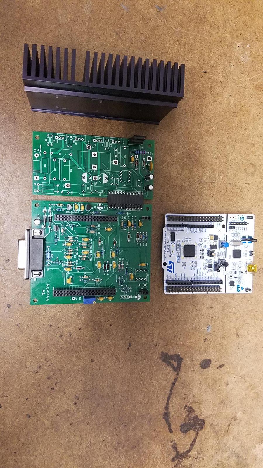
Update. The boards are here and look great. They were not that bad to design and the open source KiCad was pretty easy too learn. I did have to upgrade my PC though. The Gerber and drill files were sent to PCway.com. they were fast and efficient I got 3 different boards times 5 copies of each 15 total for $15 plus $25 for shipping from China. About 5 days from upload to delivery. I have the control board that goes under the ST Nucleo board and 2 different solenoid driver boards one is a high speed switching design the other is a linear design similar to the bosch design. I'm going to see which one I like better. The switching design is going to run much cooler. The Nucleo board was way cheaper than i could buy some of the main components for. I got some of them loaded up already. Parts came from Mouser, Digikey, and Amazon.


20230509_204246.jpg.6acbed7bf957a3b581c78f025303f60a.jpg

  • Like 1
Link to comment
Share on other sites

This thread is the reason I joined the forum and "Great work!" is an appropriate handle for the OP. The possibilities are a joy to ponder given that this control along with something like a Holley digital dash and some basic wiring could eliminate the PSG, ECM, PCM, and factory cluster (a bunch of expensive components in the event that they do fail). Thank you for the time and the updates.

Edited by wish4hemi
  • Like 2
Link to comment
Share on other sites

I know some of use want to keep these trucks as forever vehicles. I have all the parts for a p-PUMP conversion minus the injection lines and I would save me alot of time and headaches but I like the variable timing of the vp. So I'm working on alternatives.  Sadly though trying to sell aftermarket ecus and pursuing a CARB# would require a team of lawyers. The days of keeping forever vehicles and restoration maybe coming to an end in just another generation  .

  • Sad 1
Link to comment
Share on other sites

  • Owner

I agree that I eould rather keep the electronic timing versus having a static timing of a p-pump. I don't see these trucks going away any time soon. I will admit that I've done some research on software deletes on CR truck 5.9 and 6.7L yeah you can buy tuners but delete tunes are going underground. As for us less headaches and no emissions junk.

Link to comment
Share on other sites

Heya mate, love seeing your progress! I can't wait to see this in person someday! I'm still working on my custom PCM, you motivated me awhile back to dig into PCB design and I've on iteration 4 now. I've learned so much! Maybe someday I can hook my PCM up to your vp44 driver :)

  • Like 1
Link to comment
Share on other sites

@Linux I look forward to it. BTW that 8 pin ic outline is for a CAN transceiver future use. My ecm died before I was able to decode all vp44 communications but I know how to command fuel and timing. its the reply from vp to ecu with the actual amount injected that I did not figure out. I may need some recorded logs and dump into spreadsheets or even some graphs. Your PCM project with some CCD added for us Dodge guys would be nice.

  • Like 1
Link to comment
Share on other sites

14 minutes ago, Great work! said:

@Linux I look forward to it. BTW that 8 pin ic outline is for a CAN transceiver future use. My ecm died before I was able to decode all vp44 communications but I know how to command fuel and timing. its the reply from vp to ecu with the actual amount injected that I did not figure out. I may need some recorded logs and dump into spreadsheets or even some graphs. Your PCM project with some CCD added for us Dodge guys would be nice.

I can hook you up with all the logs you need! There a guy that has already done all the CCD work, just need the hardware and should be pretty straight forward. I'll see if I can include the hardware in my PCM design or something. Now that I understand that the vp44 just speaks J1939 it is a lot easier to figure stuff out :) BUT, the messages between the vp44 and ECU are custom Cummins PGN's not part of the standard from what I can tell.

  • Like 1
Link to comment
Share on other sites

×
×
  • Create New...