
BASIC AIR CONDITION REPAIR
2000 RAM 2500 DIESEL
This is a 134A Cycling Clutch Orifice Tube system which consists of a compressor, condenser, high pressure switch, orifice tube, evaporator and accumulator with low pressure switch.
.JPG.af03acb7ac46df8ec6bc10374caad425.JPG)

The compressor (a Sanden SD7H15) does two things, it moves the refrigerant through the system and it changes the refrigerant from a low pressure low temperature gas to a high pressure high temperature gas. Only refrigerant in its gas state can be compressed. There can be a catastrophic failure to the compressor if liquid refrigerant reaches it.
After the refrigerant becomes a high pressure gas it passes by the high pressure cut off switch which is located on the high pressure hose between the compressor and the condenser. This switch is used to turn the compressor off in the event of an overcharging, bad fan clutch engine overheating or blockage in the system, IE: blocked filter screen at orifice tube. The high pressure switch opens between 450-490psi and closes between 270-330psi. If the system was to over pressurize there could be A/C clutch slippage, catastrophic failure of a high pressure hose or compressor.
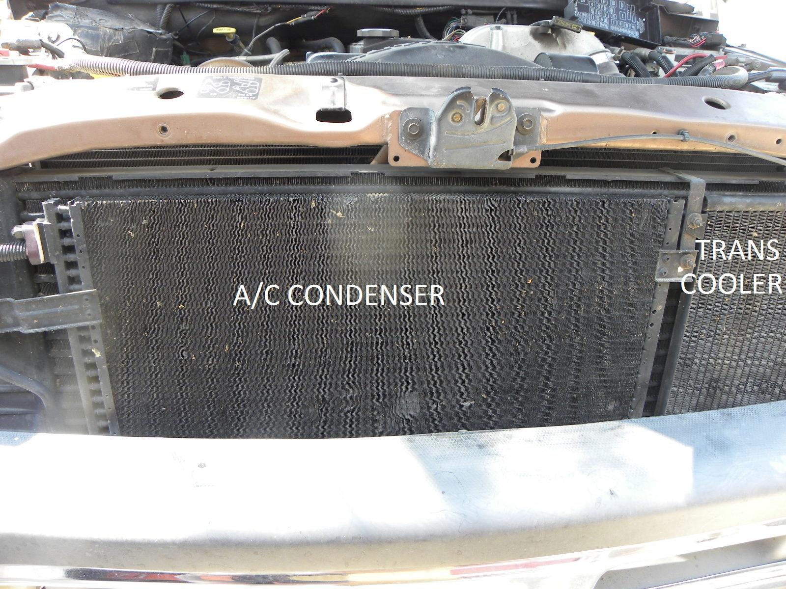
The condenser, located in front of the inter-cooler, does just that, it condenses the refrigerant from a gas to a liquid. Let's say it enters the condenser as a hot compressed gas of 120°F on a 78°F day. As the cooler 78°F air moves over the fins of the condenser some of that heat energy is absorbed by the air, heat always goes to cold. The hot gas cools enough to change states to a liquid and it leaves the condenser at 100°F. When there is a change of states there is a lot of heat energy either absorbed or given up. In the condenser that heat energy is given up to the air. The refrigerant, now a very warm pressurized liquid, flows to the orifice tube.
.JPG.22337ac518f69d637fee5d19e8815bb1.JPG)
The orifice tube is located in an AC pipe that runs along the right upper inside fender and behind the right side battery, between the condenser and the evaporator. The orifice tube is the dividing line between high pressure warm liquid and low pressure cold liquid refrigerant. There are no moving parts in the orifice tube. It has a screen for filtering, a fixed opening for refrigerant metering and a brass tube that acts as a diffuser to atomize the low pressure liquid. This screen is the only filter in the system and can become clogged with debris over time and should be replaced any time the AC system is opened for repair.
The low pressure cold liquid now enters the evaporator which acts in just the opposite way of the condenser. The temperature of the evaporator is controlled by the low pressure switch and must not go below 33°F or any moisture in the system will freeze in the evaporator and cause a blockage. Warm air blowing over the fins of the evaporator transfers its' heat energy to the cold liquid, heat always goes to cold, and cooler air exits the evaporator. The evaporator also reduces the humidity and helps filter the air in the cabin by condensation on the outside of the evaporator. As the cold liquid refrigerant absorbs the heat it changes states again and boils from a liquid back to a gas. The refrigerant now, which is mostly a gas with some liquid, enters the accumulator.
.JPG.c598afcc2bca146997cd92eb9177967b.JPG)
![air_conditioner_accumulator[1].jpg](https://mopar1973man.com/storage/attachments/monthly_2016_08/57c25a30c1c61_air_conditioner_accumulator1.jpg.36343e61a56689f9ad8d5350c93ff255.jpg)
The accumulator acts as a storage container, a liquid/vapor separator, a lubricating/cooling point for the compressor and moisture control. When the system is properly charged it is filled with 30-40% liquid refrigerant mixed with oil in the bottom and the rest is vapor. Inside the accumulator along with a desiccant bag for moisture control is a discharge tube in the shape of a U. The vapor enters one end of the accumulator and exits the other end via hose/pipe which is connected to the low side port of the compressor. At the bottom of the U is a small hole covered by a screen filter. That hole acts as a venture where oil and small droplets of refrigerant are drawn up. The oil is needed to lubricate and the refrigerant is used to cool the compressor.
If the system is under charged the refrigerant will only be a low pressure gas by the time it exits the evaporator and will not carry any oil to the accumulator. The oil will collect at the bottom of the evaporator. When this condition occurs the compressor will fail prematurely due to the lack of lubrication and cooling. If the system is overcharged there is a chance that the accumulator will become flooded with liquid refrigerant. This liquid can make its way to the compressor and catastrophic failure is most likely.
The low pressure switch is located on top of the accumulator. The temperature of the refrigerant in the evaporator is kept between 35°-45°F by opening the low pressure switch at 25psi and closing it at 45psi.
Tools Needed for Testing and Repair
-
A basic hand tool set.
-
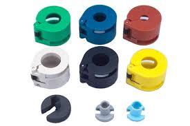
The Springlock quick release toolset pictured below is the type that works best for me. The cheap plastic disk type can be hard to use, there’s not much to grab on to for leverage if the spring sticks.
![51r6b9gIVPL._SL250_[1].jpg](https://mopar1973man.com/storage/attachments/monthly_2016_08/57c25ad1c025a_51r6b9gIVPL._SL250_1.jpg.4f6d958a5dc4badd88b7a9e4207b5807.jpg)
Springlock Quick Release Tool AC Manifold Set
-
A/C Manifold gauge set. Don't get Harbor Freight's, Mastercool or Robinair will due.
-
Digital multimeter with dc volt, 10 amp, ohm and continuity test. It doesn't have to be a Fluke, but if it has a temperature probe even better, a good meter will last a life time.
-
12 volt test light. Get the type with the ground cord permanently attached. The type that has the removable cord will give a false reading of open circuit.
-
Evacuation (vacuum) pump. Harbor Freight's 2.2 CFM pump for home use is good.
-
Halogen leak detector. I use an Advanced Test Products 5750A halogen type leak detector that's no longer available. There are other types, find one that fits your needs.
-
UV dye and leak detector. A true UV flash light and a can of dye is all you need.
-
Digital cooking thermometer. A cheap one for checking the vent temperature will work just fine.
-
Digital contact thermometer. Used for checking temperature differences in the system. Some temperature changes can be only 2-3°F. A noncontact inferred thermometer will not give an accurate reading.
-
A small digital scale. Used to measure how much refrigerant to add to the system.
-
Glass measuring cup. Used for measuring lubricating oil.
-
Safety glasses. No explanation needed.
AC Compressor Does Not Turn On
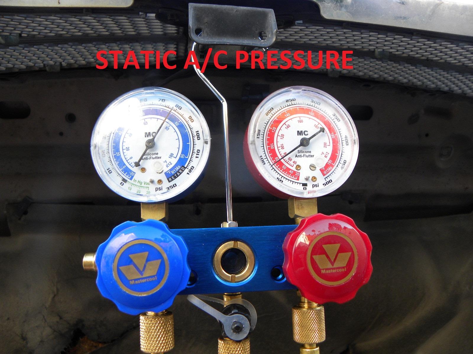
Attach your A/C manifold gauges and check static pressure (low and high pressure the same with A/C off). If the pressure is 45psi or higher start engine and turn on A/C. If the pressure is lower than 45psi then add 134A until a static reading of 45-50psi is reached.
.JPG.9d2a14406c18f87cfc14dfc26c4dd2e7.JPG)
Check if the A/C compressor clutch is engaging when A/C is selected.
If the clutch does not engage, turn the engine off, ground the brown wire at the low pressure switch at the accumulator. Start the engine and recheck the compressor clutch. If the clutch engages the problem can be a bad low or high pressure switch (≥ 5Ω is good), or open circuit in the wires between the PCM , the switches and ground. Both switches can be replaced without discharging the system.
If the compressor clutch still didn't engage with the pressure switch jumpered then ohm check the clutch coil. Remove the A/C compressor clutch relay from the Power Distribution Center (PDC) and connect an ohm meter between where terminal 87 of the relay would fit into the PDC and ground. There should be a reading of about 15Ω. If 0Ω then there is a short to ground and if the reading is 1 then there is an open circuit and testing at the connector on the compressor is needed to see if there’s a problem with the wiring or the clutch coil.
Testing for Voltage to the A/C Clutch Coil
With a voltmeter there should be running voltage from the charging system going to the compressor coil. If the voltage difference at the clutch coil is .3 volts or more than at the battery then there is high resistance in the system and it needs to be corrected. If there is no voltage to the clutch coil then check for voltage at the AC compressor clutch relay in the PCM. Remove the relay and with the engine running and AC control turned on, using a voltmeter, there should be running voltage at terminal 30 (PK/DB wire) and 86 (DB/WT wire). If there is no voltage at terminal 30 then check fuse ‘J’ (10 amp) in the PDC. If there is no voltage at 86 then check fuse #11 (10 amp) in the junction block. When there is running voltage to terminal 30 and 86 of the A/C relay then install the relay and ground terminal 85 (DB/OR wire). If there is no voltage at terminal 87 (DB/BK wire) then the relay is bad. If there is voltage at terminal 87 then there is either an open circuit from relay terminal 85 to PCM or a bad PCM.
![pin_out_d1_4[1].png](https://mopar1973man.com/storage/attachments/monthly_2016_08/57c25fdc3ff1c_pin_out_d1_41.png.95e95a38b7c4cb6a00a8146efec6f29b.png)
![Changeover_relay[1].png](https://mopar1973man.com/storage/attachments/monthly_2016_08/57c25fd5a5d96_Changeover_relay1.png.e28d198eafa00fc1ca050feafeae8e51.png)
Clutch Air Gap
Check the air gap of the A/C clutch with feeler gauges. The gap between the clutch and pulley should be between .016"-.031". If the gap is to little the clutch disk could drag on the pulley causing accelerated wear on the parts. When the gap is to big the clutch will not engage because the magnetic force cannot overcome the distance and the clutch will not engage the pulley.
Leak Testing the A/C System
If the A/C system is low on refrigerant there is a leak that needs to be repaired. There should be a minimum static reading of 50psi when doing a leak test. There are several ways to leak test the system but here are three ways you can do it at home.
First Testing Method
The least expensive way is using liquid dish soap.
![]()
Start by doing this test on a calm day or in a garage. Clean the dirt, grease and oil from the areas that will be tested making note of any large oil stains. These stains may indicate where the leak in the A/C system is located. Mix water with liquid dish soap until bubbly and either brush or spray it on one place at a time. Wait 10 minutes before testing the next area. If even one bubble forms then there is a leak in that spot and needs to be repaired. The evaporator cannot be tested this way when encased in the HVAC assembly.
Second Testing Method
Injecting a fluorescent dye that glows under a UV (black) light is a proven method with good results. Be sure to clean dirt and grease from fittings because if the leak is small the dirt covering can hide the UV dye coming out.
![436[1].jpg](https://mopar1973man.com/storage/attachments/monthly_2016_08/57c2605903f74_4361.jpg.014b4753b6390ccf63d0d6bdf168c48e.jpg)
This test is best performed in a darken area.
To do the test you first must add the UV dye to the system. There are three ways you can add a small amount of dye to the system:
-
add a can of 134A with UV leak detector in it when the system is too low to turn the compressor on (static pressure below 20psi), or
2 if there is enough pressure to cycle the compressor add a can of UV leak detector, or
3 inject the UV dye directly into the low pressure test port.
After 30 minutes of operating the A/C system the dye will have mixed with the oil and refrigerant and the system can be scanned with the UV light. If there is a leak it will show as a fluorescent stain. If no leak is detected at this time, you can recheck at any time because the dye will stay in the system. Most cheap 'UV' lights are a blue light or a black light not in the 400nm range. With that type of 'UV' light the yellow glasses must be used, a true UV light doesn't need them.
The front compressor seal can be checked by sliding an index card or heavy bond paper between the front of the compressor and the pulley. If the seal is leaking there will be a dyed oil stain on the card. For other hard to see areas a cotton swab can be passed over the spot and then examined.
Once again, the evaporator cannot be directly inspected. It may be possible, to very carefully, drill a small hole in the side near the bottom of the evaporator box. The bottom of the box can be swabbed by inserting a long cotton swab through the small hole. Any oil/dye that has dripped down to the bottom of the box will be absorbed by the cotton swab. Remove swab and inspect with UV light.
Third Testing Method
I've used an electronic (halogen) leak detector for many years with good results.
![10104_87[1].jpg](https://mopar1973man.com/storage/attachments/monthly_2016_08/57c26088c7820_10104_871.jpg.f9c35989d302a5ab0a720775203d445e.jpg)
This small hand held battery powered tool has a small fan inside the probe that draws air across a sensor. When 134A is detected an alarm sounds and a light scale is activated. The more gas that is detected the louder the alarm and more lights are illuminated on the scale.
Once again there should be no air movement around the truck. Do not clean any of the oil, dirt or grease and do not spray any carb or brake cleaner in the area. Since 134A is heavier than air it is important to keep the end of the probe below the area that is being tested, IE: under the front of the compressor and not above or the side to test for a front seal leak. The sensor is very sensitive but can be slow to react to a leak due to the time delay of the fan drawing the air over the sensor. The probe should be moved slowly at about 1"/sec and sometimes even slower. The tip of the probe must be kept clean so air can flow down to the sensor.
I have found evaporator leaks by placing the tip of the probe in the A/C drain tube or by inserting it in the center dash vent then turning the fan on low for a few seconds.
A/C High and Low Pressures
There is no set pressure for a set temperature in a mobile air conditioning system. There are just too many variables that influence the outcome. There is temperature, humidity, engine speed, engine temperature, air flow over the condenser and evaporator, condition of the compressor and a host of other things that give the final pressure reading. So, to minimize different readings when testing, it is necessary to conduct the test the same way every time. Dodge along with other manufactures suggest to do it with: the engine at full operating temperature, the engine rpms at 1000 (others say up to 1500rpm), A/C control set to A/C-Max, temperature control to cold, fan speed at max (others recommend a medium fan speed), doors and windows closed with thermometer in the center vent.
A rule of thumb for a fully charged system is the high side pressure to be 2.2-2.5 times the ambient temperature (80°F x 2.2-2.5 = 176-200psi); and, the inlet temperature of the evaporator is within 1-2°F of its' discharge temperature. Adding the correct amount of refrigerant is hard to do when just topping off a system. Anyone can 'dump' a can in but is that enough or too much. An A/C system will cool sufficiently with only a 75% charge in it but will suffer a slow compressor death due to overheating and lack of lubrication. With only a 10% overcharge the cooling efficiency will start to decline and a good chance of liquid refrigerant reaching the compressor causing catastrophic failure. The only true way to know the charge amount is correct is to evacuate the system and recharge with the correct amount.
Below are some examples of what causes high and low pressure readings:
High Side: Low Refrigerant is low, check for leaks, repair as needed.
Low Side: Low
High Side: High System is over charged - reduce charge.
Low Side: High Check engine cooling system for low
coolant/overheating, engine thermostat, fan clutch, radiator blocked , poor air flow over radiator.
High Side: Normal Air blend door not closed - adjust or repair.
Low Side: Normal Moisture in system - replace accumulator,
evacuate and recharge.
High Side: High Air in system (2%> of air by volume) - replace
Low Side: Normal accumulator, evacuate and recharge.
High Side: High Blockage in system - check for heavy sweating or orifice tube, or frost in system at
Low Side: Low orifice tube, condenser, or accumulator. Clear blockage, replace accumulator, a evacuate and recharge.
High Side: Low Refrigerant is low or restriction in accumulator or evaporator.
Low Side: Normal
High Side: Low Near static pressure – orifice tube is broken or
Low Side: High missing; or the belt is slipping; or a bad compressor; or, if compressor clutch is slipping check air gape and voltage.
Repairing A/C system
I am not going to tell you how to change a part but give some helpful hints to avoid the pitfalls.
-
Have all the parts and tools on hand ready to go. The faster you open and close the system the less of a moisture problem.
-
If you have to purge the refrigerant from the system and it can’t be captured, crack open the low and high side valves. If the valves are opened to much refrigerant oil will be forced out by the escaping 134A. You won’t know how much is lost and it makes a mess.
-
If you are replacing the compressor due to a catastrophic failure replace the orifice tube, accumulator and also the condenser. A lot of debris can get stuck in the tubes of the condenser and flushing may not clear it out. The cost of an aftermarket one is cheap and you are not worried “did I get it all out”. You will need to drain the oil out of the old compressor into the measuring cup and make note of the amount. Discard old oil. Now, drain the oil out of the new compressor then add the amount, in fresh oil, that was drained from the old compressor plus 2oz for the new accumulator and 1oz for the new condenser to the new compressor.
-
Always replace the o-rings when working on an open system. They are a possible point of future leakage, and it’s cheap and easy to do. All O-rings need to be coated with A/C mineral oil NOT PAG oil. PAG oil is hydroscopic and will cause corrosion on the outside of the hose fittings and O-rings.
-
When evacuating the system let the vacuum pump run for at least an hour, the longer the better. This is turning any liquid water into a vapor by causing water to boil. Water will boil at 70°F when the vacuum is at or greater than 29.18inHg. The vapor has to make its way out of the system to the low and high side ports. This is why it takes so long to evacuate the system. When done evacuating the system close the valves on the A/C gauge manifold and wait. If the gauges move then there is still a large leak in the system. A small leak cannot be found this way because only 15psi is being exerted inward when the system normally runs with a static pressure of 80+psi and a running high side pressure of 170+psi pushing out.
-
When first adding 134A to the system from a single use 12oz can the low side pressure will jump up to 60+psi and then come down, depending how much refrigerant is in the system, to 20-45psi. The can will also become cold due to the pressure drop in the can and the refrigerant boiling. When the can is no longer cool or cold there is no more refrigerant in the can or going into the system.
-
To expedite the charging time jumper the plug for the low pressure switch this will keep the compressor clutch from cycling off. The refrigerant will enter the system faster when the can of 134A is placed in a container of warm water. The 134A turns to a gas in the can faster due to the heat of the warm water. Only 134A in its gas state should enter the system, adding liquid 134A before the compressor can destroy it.
-
The A/C system requires 32oz of 134A for a full charge. When using a single use 12oz can you’ll need 3 cans. After adding 2 cans (which is 24oz) weigh the third can on the kitchen scale and make note of the weight. When adding the remaining 8oz (2/3 of the can) check the weight of the can occasionally. When the can is 8oz lighter you’re done.
The above information is not all inclusive for A/C repairs. However, I hit on a lot of the procedures, tools, and knowledge needed to perform basic air condition repairs for the 2000 RAM 2500 DIESEL.
Written by:
J. Daniel Martin, Martin’s Mobile Maintenance
AKA: IBMOBILE
8/27/2016
-
 4
4
-
 1
1