

Arduino climate control
- Replies 11
- Views 2.5k
- Created
- Last Reply
Top Posters In This Topic
-
Scottfunk 5 posts
-
kzimmer 3 posts
-
Mopar1973Man 2 posts
-
Me78569 1 post


Popular Days
Most Popular Posts
-
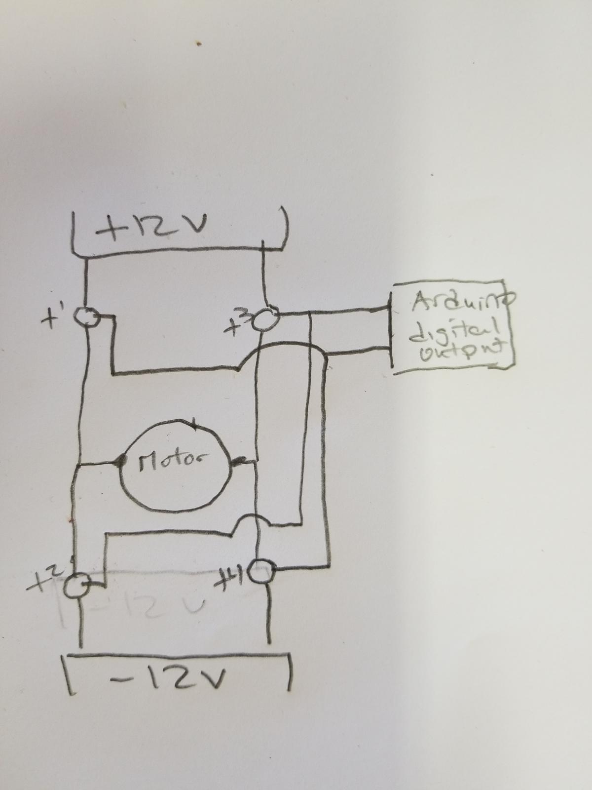
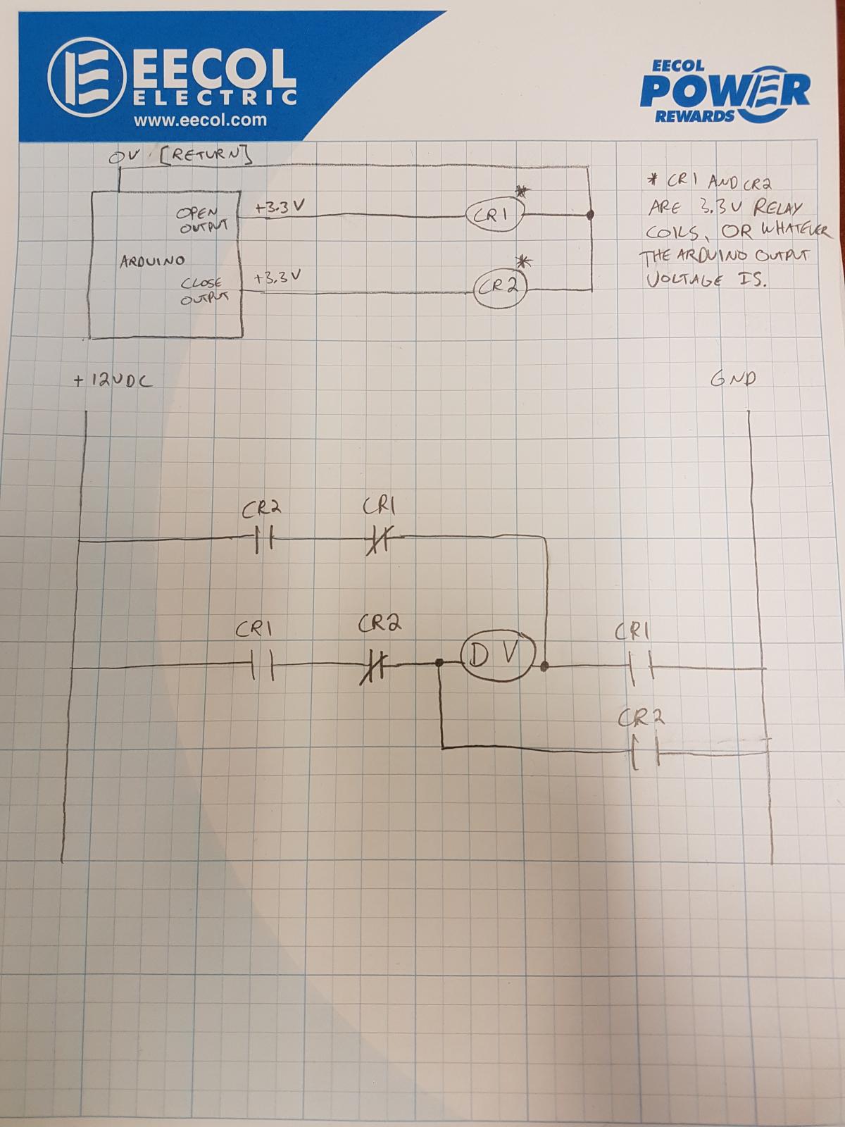
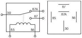
Can you use two digital outputs from the Arduino, both triggering relays? One output for open, triggering a relay that switches +12v, the other for close, triggering -12v. If you do, get a relay with
.jpg.8e44c791dac99b1a4ec9f4ff4e3e7d8f.jpg)
I'm asking this because I know there are a lot of tech savvy people on this forum. I'm building an arduino based climate control system for my Yukon because I no longer have vacuum. I have built an app to control the system that consists of three slider bars (fan speed, temperature control, and zone control.) Controlling the fan and the flapper door haven't proven to be too difficult, however the coolant diverter valve has turned out to be a different story. Does anybody have any useful suggestions about how to control this with an arduino? The tech guy from the company I talked to said the direction of the diverter valve is changed by changing polarity to the motor. Can this even be done with an arduino? And how do I boost the signal from the 3.3V coming out of the arduino to the 12-24V needed by the valve? The pot is just feedback to the arduino letting it know what position it's in, like a tps. It's mostly just the polarity swap I'm not sure how to do.
Edited by Scottfunk