Jump to content
Posted

Hi everyone as I'm relatively new to this I would like to say thanks for the add I have been researching on making a standalone controller for my 351 vgt I was going the lilbb route but the website no longer works you can't buy anything and cannot register to ask in their forum and I seen the write-up in this form which is very detailed and thorough but my main question is has anyone done it here that still runs it and did you run lbb's box or build your own? I'm looking for the breadboard to build the lbbs box cause I have everything to solder it into it

  • Replies 65
  • Views 10.3k
  • Created
  • Last Reply

Top Posters In This Topic

Most Popular Posts

  • Mopar1973Man
    Mopar1973Man

    Talk to @Me78569 he's already done the stand alone controller for VGT turbo and made it all work on a 2nd Gen 24V engine actually reading the ECM through the CANBus plug. Exhaust brake and and full co

  • 1/4 should be plenty.  I think I used a 1/8 but Id ont remember.

  • Breaking it down,  U = Chip quality/grade A = Automotive temperature range U = Chip format, in this case, Umax size, 3x3mm with 8 or 10 leads B = Lead count, 10 or 64 (+) = le

Posted Images

Featured Replies

Maxim 9924 use for  2 wire RPM sensor.


"DIV / 2" Sorry for that. Arduio is 10 bit ADC or maybe 8 bit (I can not remember) if so then ×4 to get in range of actuator.


The actuator may have current sensing and pulsing encoder to detect limits of vanes you may need to assemble to turbo for calibration to work.


I don't  use a CAN shield. I use a MCP 2515 based board on amazon form China names vary SMAKN or NyRen.

It has a different crystal than most shields so the library will need a different define or setting. I don't use a CAN library either. You can skip the message filter and mask too with only 2 simple nodes.

I sold that truck ~3 years ago ish I dont remember much of this anymore.  

thanks guys,

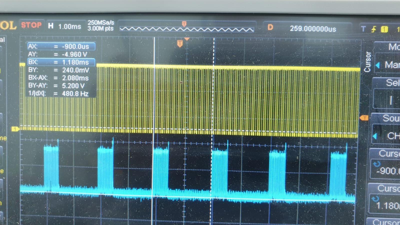
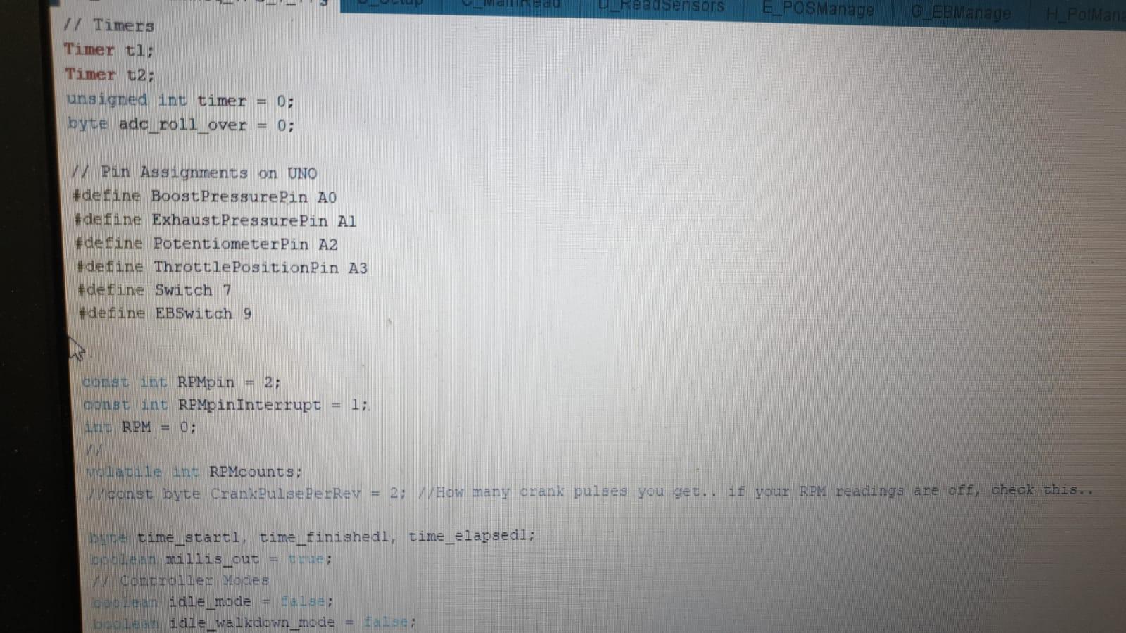
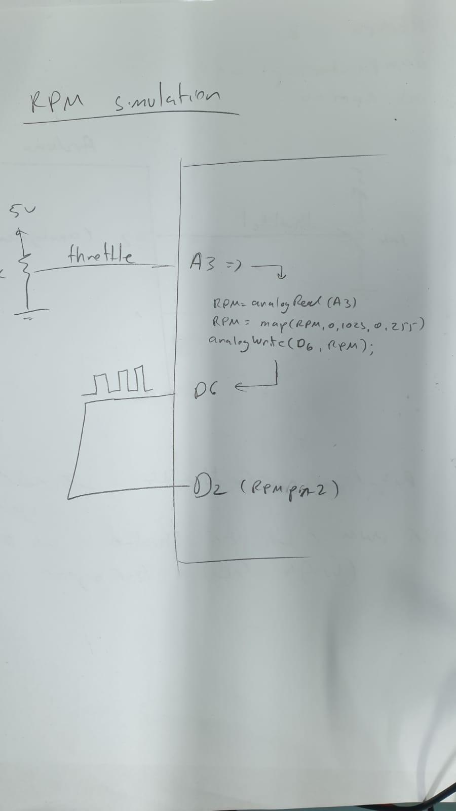
you use the max9924 in order to sample the car's motor rpm and feed it back to the Arduino's pin 2 (if i remember right).

according to Me78569 if I close the switch (pin7 to ground), the pot effect directly on the vanes without the need to calculate the RPM and so, am I right?

I'm looking for someone who succeed in operating the actuator on the table and can share with us what is the right process without the need to connect the actuator to the cars turbo.

anyway other thoughts will be great :-)

and we have a winner !!!!! :USflag:

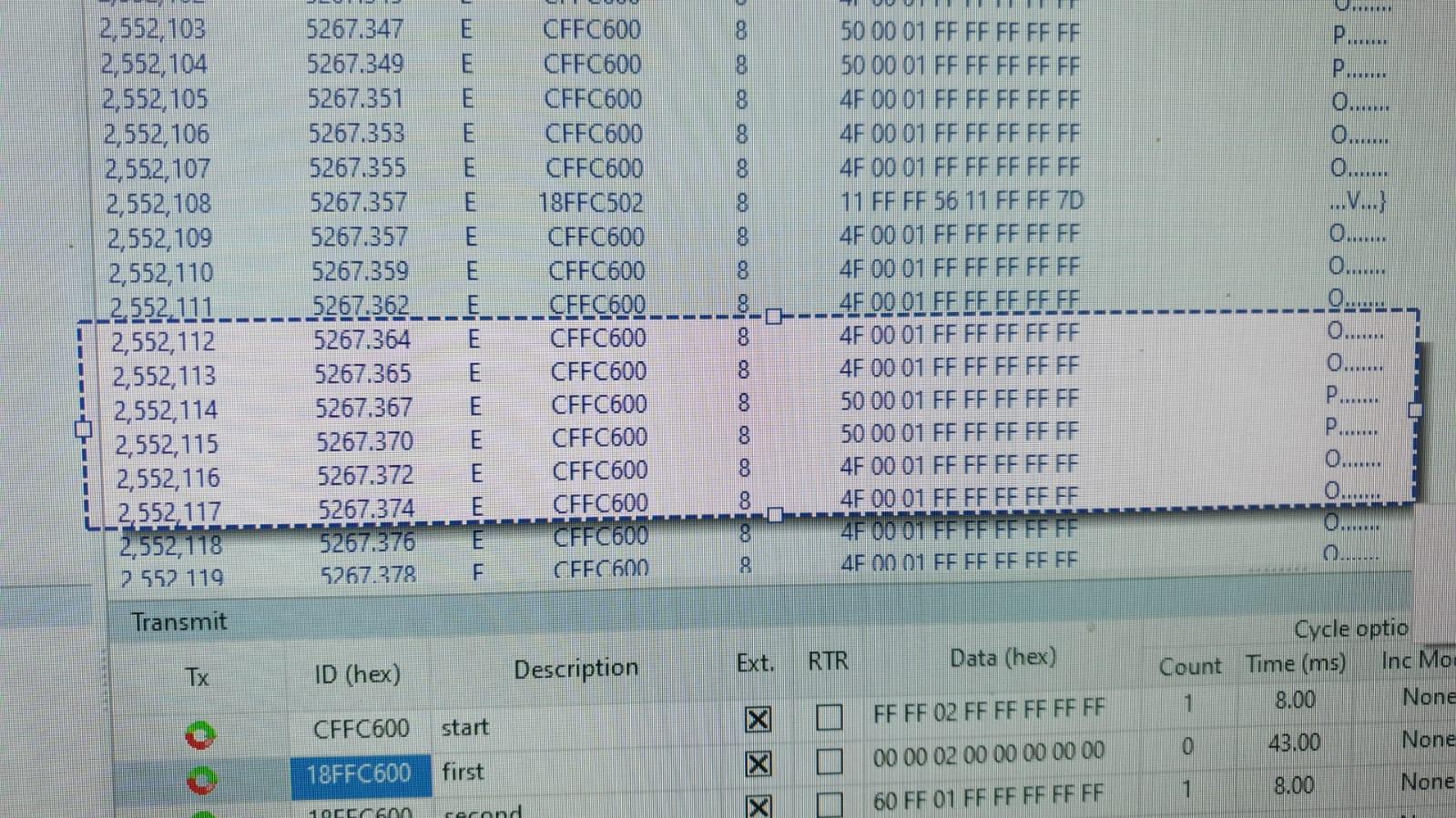
so, few minutes ago I wrote that I'm looking for more ideas and now I'm happy to tell you I succeed to control the actuator.

so, first of all, the actuator must be calibrated in order to be control by the Arduinos software.

after the calibration I was able to control the movements with the boost pot.

I'll try to upload short video of what I did so everyone can learn.

sorry for the video resolution....

Thanks everyone for the knowledge and the willing to help.