Jump to content
Looking for Staff Members
Posted

Hello everyone,


New to the forum here, have a 2000 Dodge 24 valve. I’m a mechanic by trade, bought the the truck off one of our customers. He had this issue towards the end of his ownership, truck would surge during idle and the odd time would throw APPS code but he could still drive it. 
 

The trucks had a couple different APPS sensors, OEM and aftermarket. When I bought the truck last summer I did a ton of upgrades/maintenance, starter, alternator, 2 new batteries, FASS and sump, fuel pressure gauge and a bunch of other things non related to the problem. I did all the APPS testing between sensor and ECM and everything checked out. 
 

After doing the timbo APPS my issues seemed to go away (the alternator change was around this time too). We have a truck bed camper and went on a couple long trips with no issues. I don’t drive it much in the winter but again when I did, no issues. The start of this year also had no issues, and then things slowly started to creep back. I’d be sitting at a stop light and truck would kick up a bit, started becoming more frequent, and now it’s dead pedalling again, I’ll take off for work in the morning, I’ll be trying to come to a stop and RPMS will stay high, then 2 minutes later CEL comes on and no throttle. Takes me a while to get into the system with my scanner, I’ll clear it and I can drive but will either rev real high right away and trip the light or it’ll throw it a minute down the road again. But then if I work through it enough times, and the truck warms up enough I can get going with no issues. I can go somewhere, shut the truck off, go in somewhere and drive all the way home, again no issues. But if the trucks cold or sitting for days it’ll give me issues.


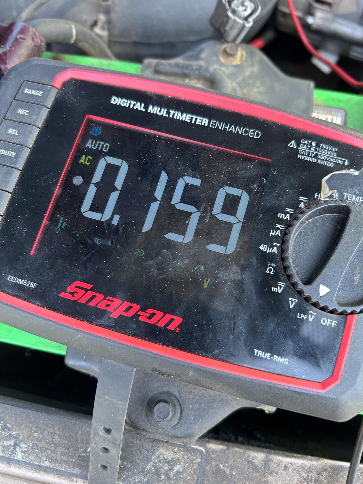
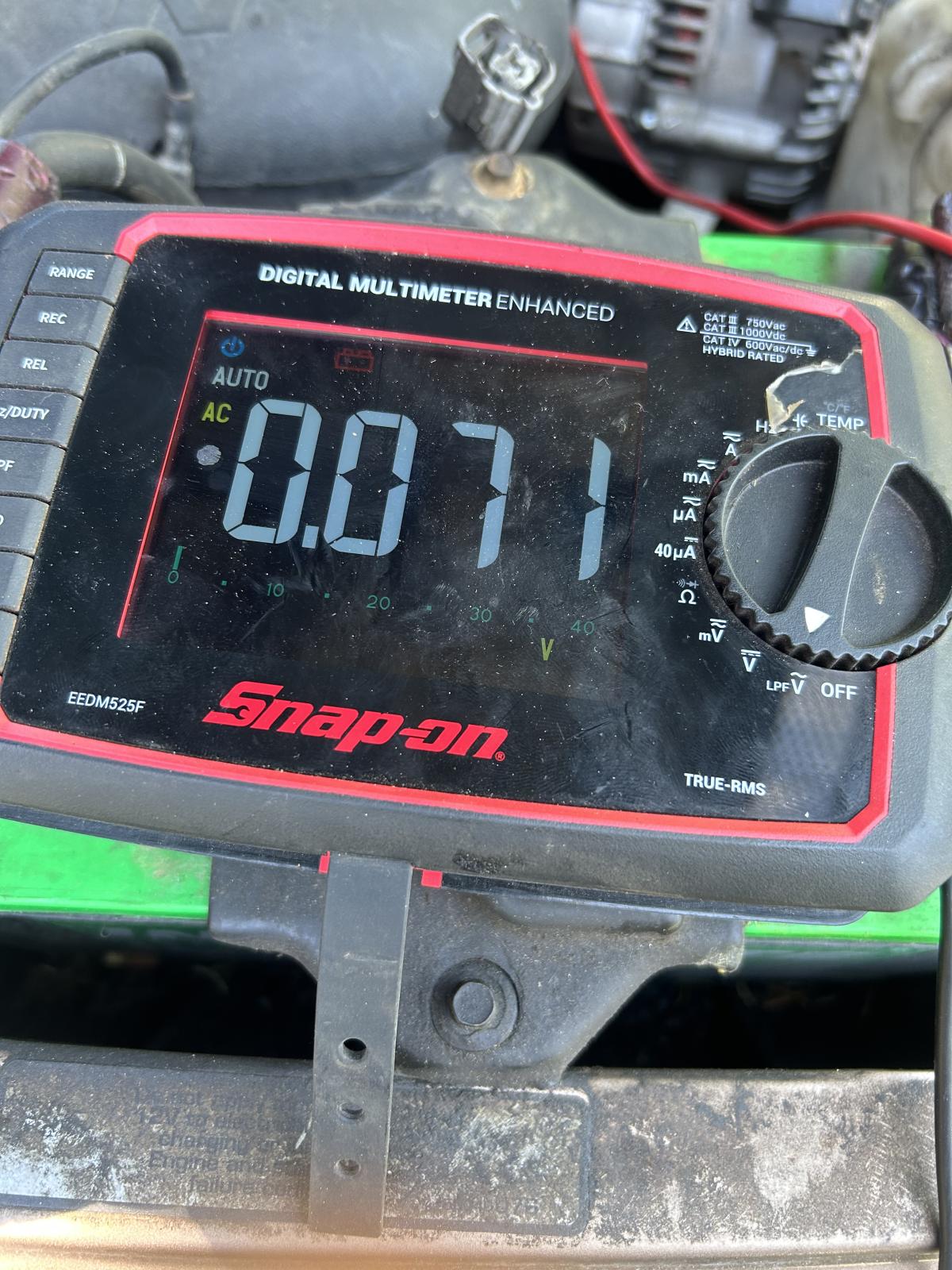
I checked for AC noise and am getting 0.127V, is this possibly an alternator gone bad? Like I said I replaced it last year with the timbo and was good for awhile but now a year later dealing with the same problems. Just want to make sure I’m not missing something here. Seems weird to me that it goes away when the truck warms up. Any insight would be greatly appreciated! 

IMG_6135.jpeg

  • Replies 51
  • Views 3.2k
  • Created
  • Last Reply

Top Posters In This Topic

Most Popular Posts

  • Tractorman
    Tractorman

    Sounds like  you have been thorough in taking care of things since you acquired the truck.    Have you checked the conditions of all battery connections and frame / body wiring grounds? 

  • I would do this step, first.  It would be good to know whether or not a false signal is being generated at idle.   Since the DTC states, "Idle Validation Signals Both Low Problem detected wi

Most Helpful Posts

  • This doesn't mean that the APPS is faulty - it just means that there is an output signal at idle when there shouldn't be. Need to know where it is coming from. More troubleshooting needed. Since I

Posted Images

Featured Replies

  • Author
8 hours ago, Tractorman said:

Glad to see you are performing voltage drop tests. Which wire has the .5 voltage drop? I am assuming that you are using the starter for the load while reading these values.

I have a Timbo APPS on my truck. I will test it with my OBDlink LX for behavior at idle when I go to town later, and then report back.

  • John

I was just checking across the wire from end to end. Honestly I can’t remember which wire it was, I just took pictures of the multimeter readings. I should have recorded it better.

And okay sounds great thanks. My readings are zero unless I’m on the throttle, but I did notice the odd time while I’m cruising it dropping out to zero but that could be this scanner, it’s kinda slow and laggy. And then now I’ve noticed it going up when the trucks revving and my foots off the throttle.

35 minutes ago, DunnerCummins24 said:

And then now I’ve noticed it going up when the trucks revving and my foots off the throttle.

It sounds like you have confirmed that a false signal is being generated in the APPS output circuit. It would stand to reason that the engine rpm's would increase if a signal is present.

Back to a previous statement of mine that was meant as a question - are you using the starter for a heavy electrical load when performing your voltage drop tests?

By the way, my throttle APPS output always showed zero at idle on the OBDLink scanner.

  • John

Edited by Tractorman

  • Author
25 minutes ago, Tractorman said:

It sounds like you have confirmed that a false signal is being generated in the APPS output circuit. It would stand to reason that the engine rpm's would increase if a signal is present.

Back to a previous statement of mine that was meant as a question - are you using the starter for a heavy electrical load when performing your voltage drop tests?

By the way, my throttle APPS output always showed zero at idle on the OBDLink scanner.

  • John

I didn’t use the starter as load when doing the tests, are you able to explain that?

Have you seen many Timbos go bad? All my wiring between APPS and ECM is good. Timbo is maybe just over 2 years old.

Thanks for checking that out on yours.

1 hour ago, DunnerCummins24 said:

Have you seen many Timbos go bad? All my wiring between APPS and ECM is good. Timbo is maybe just over 2 years old.

This doesn't mean that the APPS is faulty - it just means that there is an output signal at idle when there shouldn't be. Need to know where it is coming from. More troubleshooting needed.

1 hour ago, DunnerCummins24 said:

I didn’t use the starter as load when doing the tests, are you able to explain that?

Since I don't know what your level of skill is with electricity, I will just start with the basics. Let's say you wanted to check the condition of the crossover cable by using a voltage drop test. First, you would need to understand what would be normal for the test results.

There are two batteries (wired in parallel) and a starter on your truck. The starter will draw at least 400 amps when cranking. This means that 200 amps will be supplied by each battery. Consequently, when the starter is operating, the positive and negative cable of the driver side battery and the positive (crossover cable) and negative cables of the passenger side battery will be handling 200 amps each. By design there will always be a voltage drop during the starter operation - there has to be, otherwise current would not flow. The maximum allowable voltage drop in a complete positive circuit is generally .5 volts and in a complete negative circuit is generally .2 volts. The positive circuit has a higher allowable voltage drop because there are usually more switches and connection points than in a negative circuit.

Voltage drop measurements can be taken at different points with a voltmeter while the circuit is under an electrical load. Voltage drop tests taken without the circuit under an electrical load will show results that are meaningless.

So, back to performing a voltage drop test on the crossover cable. This usually works best using two people. One person will be in the cab and will crank the engine as instructed for a specified period of time. Be sure to be safe - truck in neutral / park and park brake set. Remove the fuel pump relay (in the PDC) for the VP44. This will allow the engine to crank continuously without starting.

Set your voltmeter to a manual DC voltage scale of two decimals - example: battery shows 12.67 volts DC on the meter. Do not use the floating scale. Place and hold the positive lead onto the passenger side positive post of the battery (the actual post, not the clamp). Place and hold the negative lead onto the eyelet at the other end of the crossover cable. Your meter should read 0 volts. Instruct the other person to crank the engine for 10 seconds (no interruption). A reading of .1 volts or less indicates that the crossover cable is in very good condition. A reading of .7 volts (for example) would indicate that the cable needs to be replaced. This voltage drop test allows you to see the true condition of the crossover cable while over 200 amps are passing through - a real life situation.

  • John

  • Author
10 hours ago, Tractorman said:

This doesn't mean that the APPS is faulty - it just means that there is an output signal at idle when there shouldn't be. Need to know where it is coming from. More troubleshooting needed.

Since I don't know what your level of skill is with electricity, I will just start with the basics. Let's say you wanted to check the condition of the crossover cable by using a voltage drop test. First, you would need to understand what would be normal for the test results.

There are two batteries (wired in parallel) and a starter on your truck. The starter will draw at least 400 amps when cranking. This means that 200 amps will be supplied by each battery. Consequently, when the starter is operating, the positive and negative cable of the driver side battery and the positive (crossover cable) and negative cables of the passenger side battery will be handling 200 amps each. By design there will always be a voltage drop during the starter operation - there has to be, otherwise current would not flow. The maximum allowable voltage drop in a complete positive circuit is generally .5 volts and in a complete negative circuit is generally .2 volts. The positive circuit has a higher allowable voltage drop because there are usually more switches and connection points than in a negative circuit.

Voltage drop measurements can be taken at different points with a voltmeter while the circuit is under an electrical load. Voltage drop tests taken without the circuit under an electrical load will show results that are meaningless.

So, back to performing a voltage drop test on the crossover cable. This usually works best using two people. One person will be in the cab and will crank the engine as instructed for a specified period of time. Be sure to be safe - truck in neutral / park and park brake set. Remove the fuel pump relay (in the PDC) for the VP44. This will allow the engine to crank continuously without starting.

Set your voltmeter to a manual DC voltage scale of two decimals - example: battery shows 12.67 volts DC on the meter. Do not use the floating scale. Place and hold the positive lead onto the passenger side positive post of the battery (the actual post, not the clamp). Place and hold the negative lead onto the eyelet at the other end of the crossover cable. Your meter should read 0 volts. Instruct the other person to crank the engine for 10 seconds (no interruption). A reading of .1 volts or less indicates that the crossover cable is in very good condition. A reading of .7 volts (for example) would indicate that the cable needs to be replaced. This voltage drop test allows you to see the true condition of the crossover cable while over 200 amps are passing through - a real life situation.

  • John

John,

Thanks a ton for laying that out, i will 100% be doing that. Do you think that would cause my issue?

We are supposed to go camping again next weekend and I don’t have a whole lot of time. Two questions I have are I was going through old threads here and saw moparman said for alternator AC noise that .05 is marginal and .10 is failed. I was having .7 with accessories off and .125 with everything on. Is that an issue? I had some other guy tell me that’s totally fine?

Also saw a test on blue chip diesel on back probing the APPS and seeing if the voltage increases when the throttle kicks up, they said to route it into the cab and check it while driving with an analog meter. But it’s doing it consistently at idle, that’s something I could check fairly quickly and easily.

23 hours ago, DunnerCummins24 said:

Also saw a test on blue chip diesel on back probing the APPS and seeing if the voltage increases when the throttle kicks up, they said to route it into the cab and check it while driving with an analog meter. But it’s doing it consistently at idle, that’s something I could check fairly quickly and easily.

You could do that - it could confirm what your scanner is saying. Also, you mentioned that you are getting the P0121 code.

P0121 (M) Accelerator Position Sensor (APPS)

Signal Voltage Too Low

APPS voltage input below the minimum acceptable voltage.

You could check this voltage (5 volts supply) at the same time to see if it is fluctuating while the symptoms occur.

23 hours ago, DunnerCummins24 said:

Thanks a ton for laying that out, i will 100% be doing that. Do you think that would cause my issue?

The condition of wiring and wiring connections (both positive and negative) are crucial on these trucks - so, yes, it is possible for this to be the problem.

  • John

14 minutes ago, Mopar1973Man said:

Small correction...

Interesting. I copied mine from my 2002 FSM, however your P0121 description actually seems more related to the symptoms that are occurring. What is the source of your information?

  • John

  • Staff
On 7/2/2025 at 6:51 AM, DunnerCummins24 said:

moparman said for alternator AC noise that .05 is marginal and .10 is failed. I was having .7 with accessories off and .125 with everything on. Is that an issue?

You will want to see .05V or less measured at the back of the alternator after the engine reaches operating temperature, no grid heaters operating, and engine at idle. My truck's ac voltage is .03-.04.

  • Author
11 hours ago, Tractorman said:

You could do that - it could confirm what your scanner is saying. Also, you mentioned that you are getting the P0121 code.

P0121 (M) Accelerator Position Sensor (APPS)

Signal Voltage Too Low

APPS voltage input below the minimum acceptable voltage.

You could check this voltage (5 volts supply) at the same time to see if it is fluctuating while the symptoms occur.

The condition of wiring and wiring connections (both positive and negative) are crucial on these trucks - so, yes, it is possible for this to be the problem.

  • John

10 hours ago, IBMobile said:

You will want to see .05V or less measured at the back of the alternator after the engine reaches operating temperature, no grid heaters operating, and engine at idle. My truck's ac voltage is .03-.04.

So I rigged up an analog volt meter and ran two wires through the firewall. Ones back probed into the signal wire and the other is from battery ground. I tried to drive the truck Tuesday and couldn’t even get it out of the driveway. So I figured this is a perfect time to test this with the truck acting up. I did also clear the codes. But I drove 35km to work and 35km back with zero issues, truck ran great. I did test it with key on engine off and took the APPS through its range on the voltmeter and it was perfectly steady without hesitation. Now I just have to keep driving it to catch it when it acts up and see what the volt meter does?

Also all my AC voltage tests were at first startup so I checked it after driving home with everything off and it was .058vac.

IMG_0692.jpeg

Edited by DunnerCummins24

That is a good way to test. Will be waiting to hear back.

Also, have you verified that the mechanical set screw for the throttle cable is in good condition and that the throttle cable always returns to the mechanical stop when operating the throttle?

  • John