Mopar1973Man
Owner
-
Joined
-
Last visited
Everything posted by Mopar1973Man
-
I would use FelPro or Mahle gaskets over any Cummins gasket any day. Just a heads up Cummins does not produce gaskets like the head gasket is produced in China by BLK.
-
Only thing that is required that it is a GL-4 lubricant. I would suggest that you don't attempt to use the same factory weight of oil. Factory suggested viscosity I will say it too thin. Especially if you work your transmission heavy like I do. For sure add a transmission temperature gauge. I will admit I've ran a few times as high as 240*F which cause my last failure being the lube was too thin and started breaking down the viscosity and then taking the hard facing off the gears. 50 weight engine oil is equal to 90 weight gear lube. 75W-85 is equal to 10w30 engine oil just think when the temps rise to 200*F it does get get rather thin.
-
I dropped all the high price junk fluids (Mopar, Redline, AMSOil, Etc.)... I switched over to a synthetic 50 SAE used in Eaton Fuller 10 speed transmissions. So far had good results and no issues. The whole scare about it be too thick or affecting syncros is not true. Shift quality is great. I've used both Mobil 50 SAE Transmission Fluid and now using Valvoline 50 SAE Transmission fluid. No issues. I'm planning soon to drop the fluid out of Thor which is a G56 transmission (6 speed) and get rid of that junk ATF+4 and load it with Valvoline 50 SAE transmission fluid. I've done this for a previous customer as well and he loves it.
-
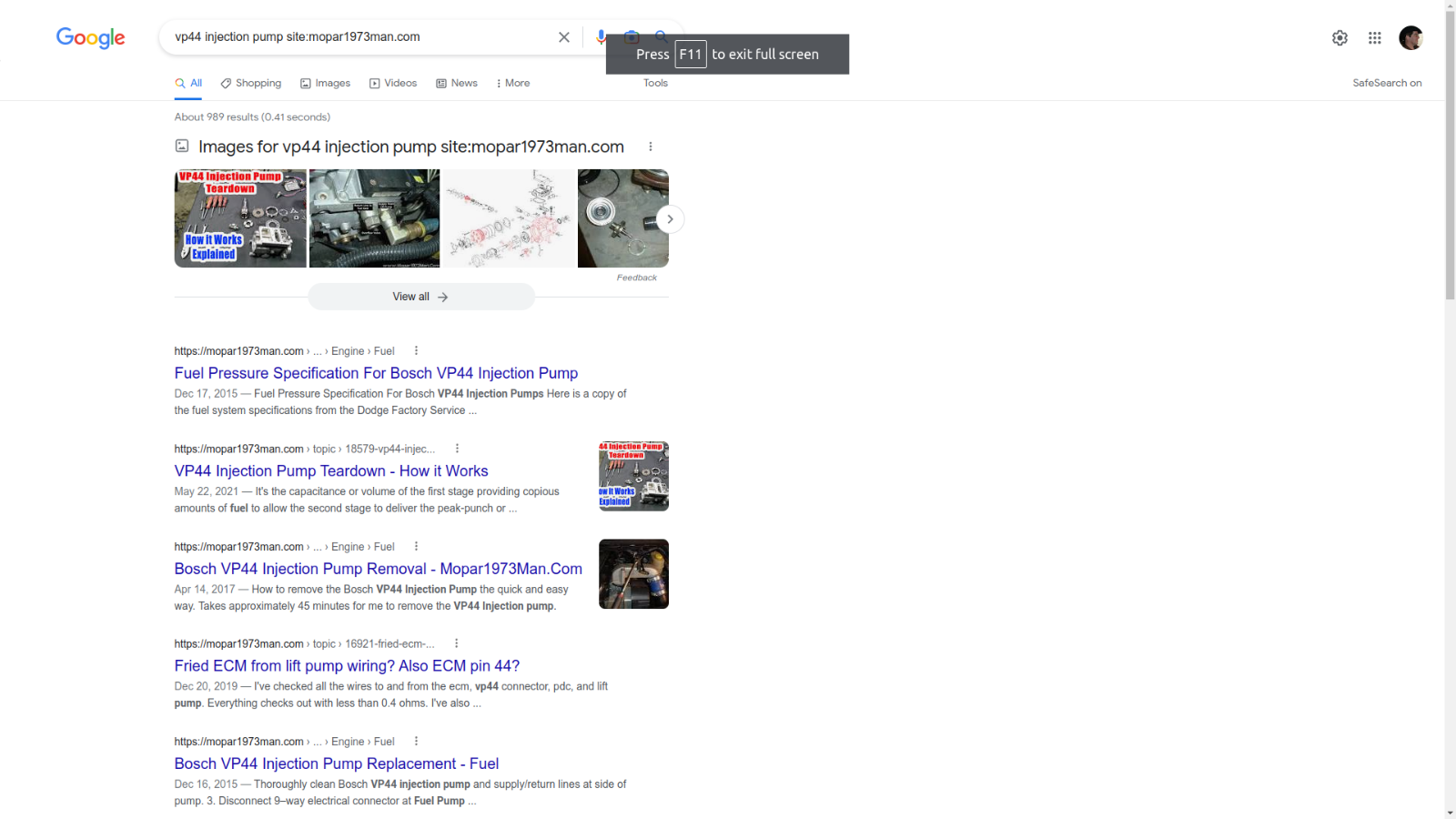
That's why I pick a product and do a review of the products I purchase. Everything I've done to my truck is all in history here on the website. If you want to do a Google search just add "site:mopar1973man.com" to the end of your search and it will dig through the website for what you are looking for. Like my example.
-
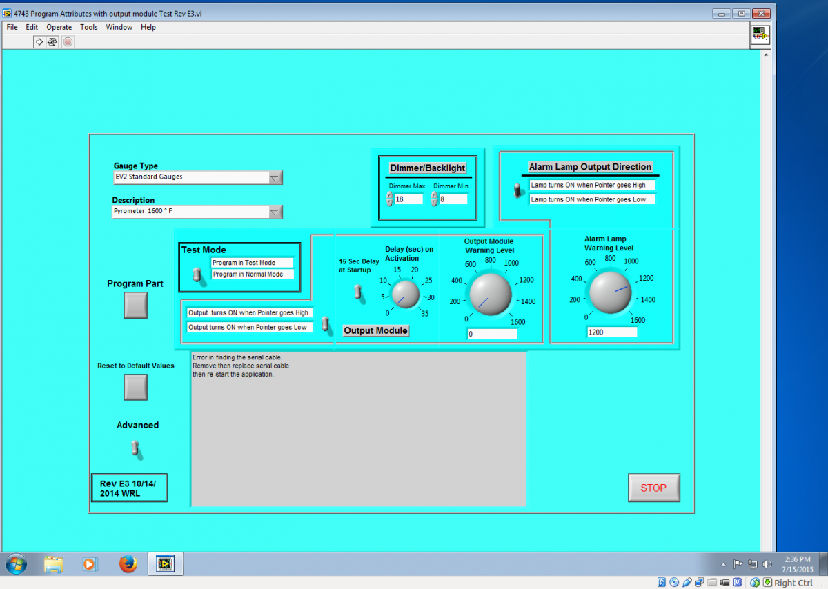
Here is the ISSPro EV2 software and the options. Showing my Pyrometer settings. Here is the entire post on it...

-
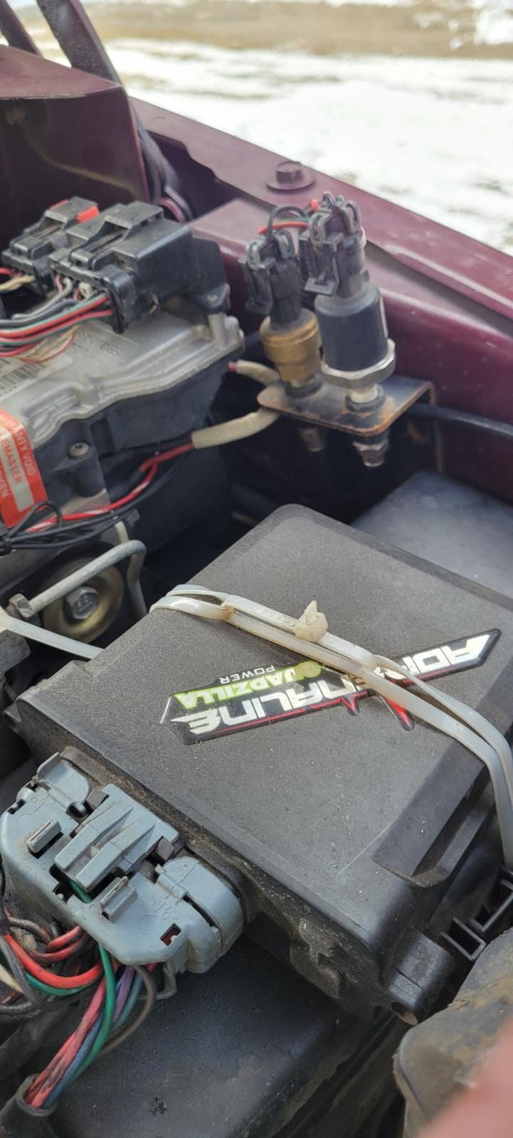
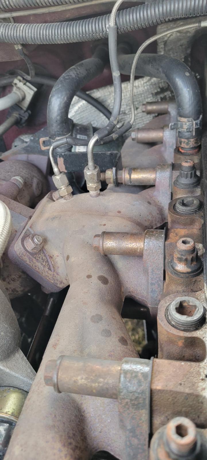
Daisy chained wiring... Sorry the photo is upside down but the boost fitting is just behind the fuel filter... My sensor are not on the engine but mounted on the fender... Boost and fuel pressure... Both pyrometer probes for the Quadzilla and ISSPro EV2... Needle valve and snubber just after... No sensor here its on the fender in the above photo.

-
I would highly suggest the ISSPro EV2 series over any other gauge on the market. ISSPro is USB programmable for the warning light, needle reaction speed, LED light to match the light level of the cluster, then you can even program a option relay to turn on and off different thing. Example Trans Temp gauge programmed for waring light at 220*F and then program the relay to switch on a cooling fan at 160*F. Then change the needle speed to be more average that accurate.
-
Varies... Might be as low 20 PSI or as high as 35 PSI. I know when I blew my head gasket I was shocked my ISSPro EV2 showed 53 PSI but the Quadzilla was 69 PSI shown in the logs. Boost gauge is the most accurate. The only thing the Quadzilla worries about is from 0 to 30 PSI being that is all the fuel map that it can calculate. Above that point it doesn't matter being it will use the +30 PSI fuel setting.
-
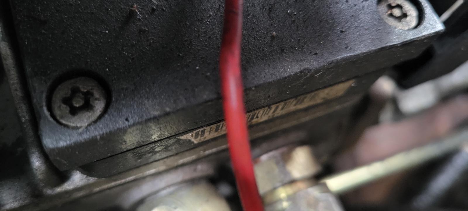
Yup. That was my mistake on my first Stealth Plate I grabbed the security 6 point torx but still didn't fit because it was a 5 point. Then seen in the bottom of the bag there was a Torx plus bit and BAM! Easy job when you have the right tools.
-
Yes Sir. I'm willing to work for you at a $100 a tune and give you unlimited updates for 30 days. We could get together on the phone gather up info make a base tune. Let you test drive call me back and we will produce a update tune. All the progress will be saved in the Download file and show all the progress so we can back up to a previous if needed. Let me know we can build tunes.
-
Myself I typically run Level 2 on the Quadzilla being with +150 HP DAP Injectors (7 x 0.010 popped at 320 bar) that more than enough power for daily driver use. Level 3 is more or less like my Sport Street mode. I don't really use the wire tap but to show off to clients. That typically will push them back in the seat and you see the "Oh chit" face come, I just smile. Now with my current tune, I'm greatly defuled on the low boost realm. Way better snow and ice performance.
-
https://www.amazon.com/KAIFNT-5-Point-Tamper-Proof-Security-7-Piece/dp/B07TC79LVH
-
It could but, I wouldn't trust it fully. If you can spool fast its possible to blow past the limit briefly before the defuel limit kicks in. Just depends on how slow your acceleration then it will lean right up against it and defuel slowly. This is my experience on Beast... All I can say is try it and see how it works out.
-
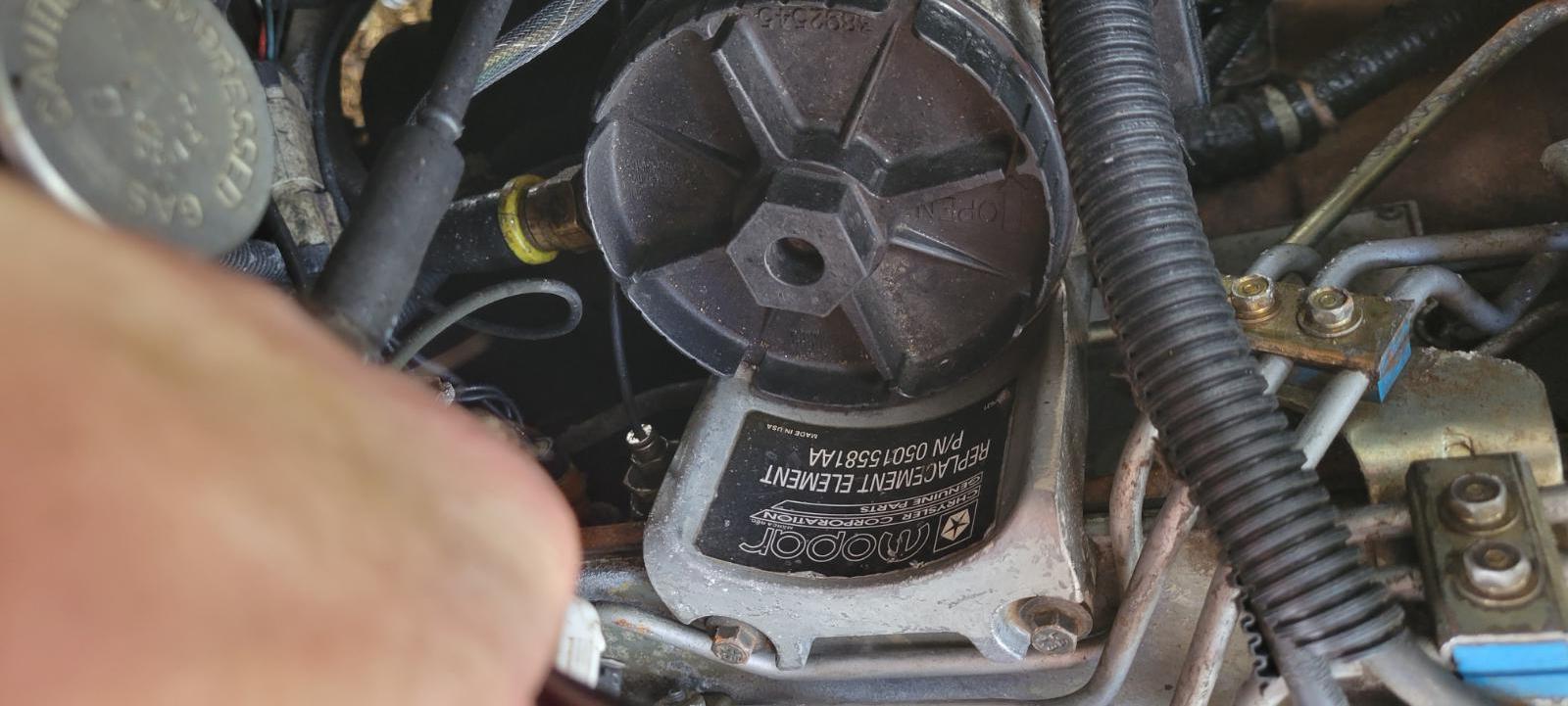
NAPA gasket is all I ever used. Now make sure your cover isn't warped and that there is no issues. Do NOT use silicone on the cover or gasket. I just slip the new gasket on making sure that its facing the right direction typically there is a tab showing direction. Then tighten the bolts as usual and reassmeble the VP44 into the gear case.
-
True Bosch certified pump is NOT a T25. Look security pin in the center and its not 6 point but 5 point.
-
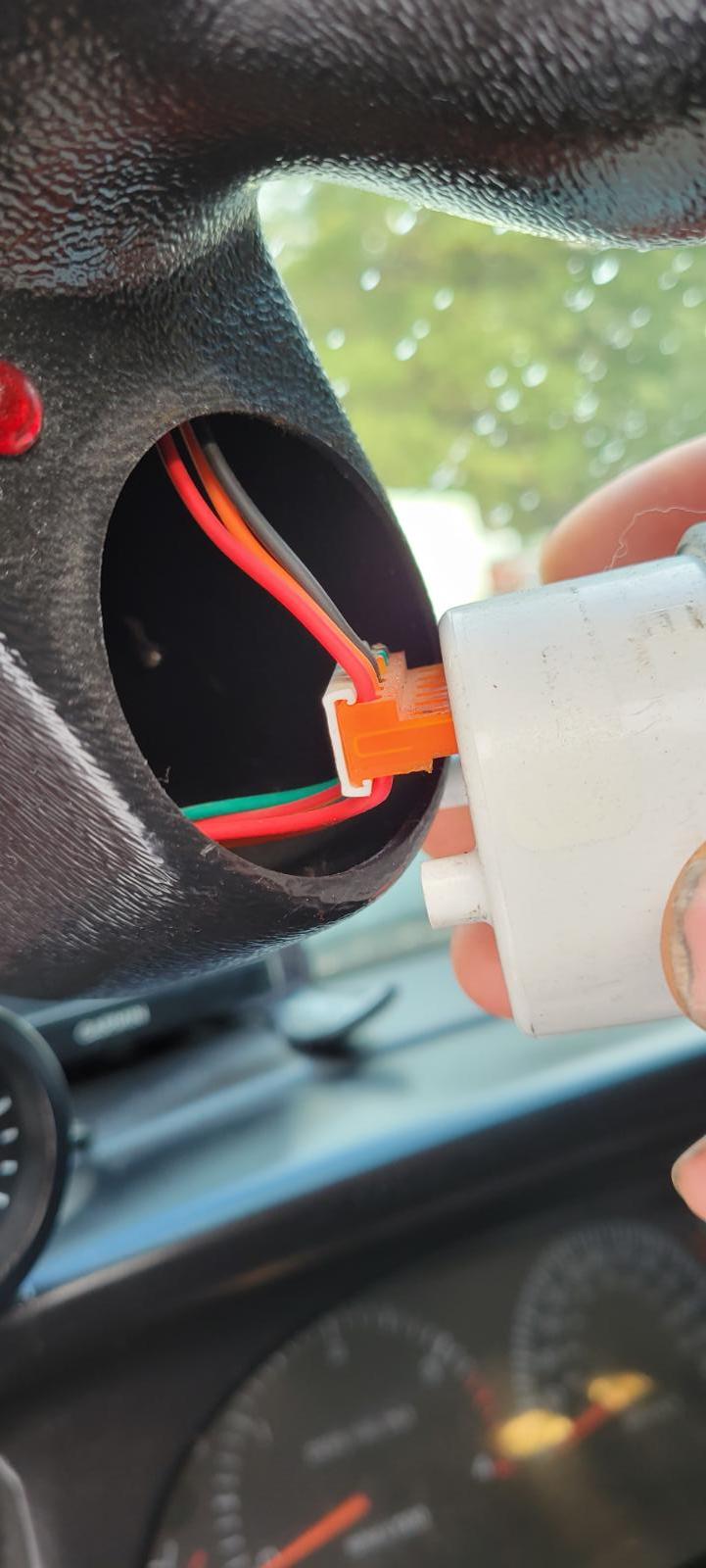
Reverse it. Now if the ECM was booting up but PCM wasn't talking it would start but things like alternator won't work being the PCM doesnt recieve the tach signal from the ECM.
-
CCD typically will not prevent starting... Now the missing WAIT TO START will 100% of the time. Being that ECM never booted up and is not responding at all. The fact that CCD bus error means the PCM booted up and attempted to talk to the ECM and since the ECM is completely brain dead it will not repsond nor start being the is not software to turn on the fuel pump relay (power for the VP44) and then no information will be fed to the VP44 being the software is not booted. I would give @Auto Computer Specialist a call and have the ECM tested out and follow their suggestions on fixing.
-
Strange I've jumped many vehicles and never unhooked the Quadzilla. No damage. No wait to start is a ECM death sentence, then the CCD codes are most likely because the ECM is not responding because the ECM never booted up which goes back to the lack of wait to start light.
-
My Father-in-law got a 2017 Dodge Hemi truck and it 3/4 ton. It looks like the previous owner hit a gooseneck hitch in the corner passenger side. Let me know if anyone has a tailgate white hopefully.
-
Here is my old post...
-
Me... I opted for the PIAA Driving light LEDs (15w) and they are actually brighter than my actual Morimoto D2S HID headlights. I will warn that cold country where it snows they will snow over in a bad storm and block the light.
-
Would be a good idea to have the tool for keeping the ABS happy and being able to program the wheel size and gear ratio. Especially for someone that changes tires and sizes between street and track.
-
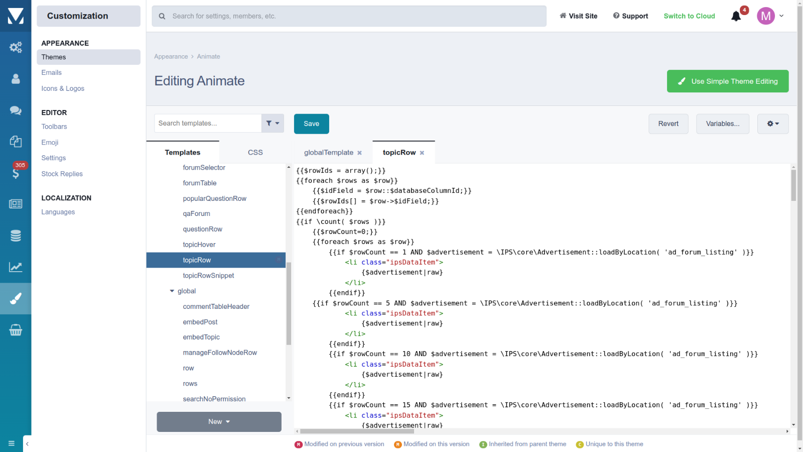
Yeah this is what I deal with behind the scenes... Actual screenshot of the internal code of the website. Now you all understand I'm responsible for all the software myself. Anything I need I have to build myself to make the website work and display way we need it to display. This is why I dumped the custom theme skin because the code work was just eating way too much time to keep the site up to date. Make everything worse my server is NOT here at my house in Idaho. Actually its in Michigan. I have to work all this remotely from my PC to Michigan and do it on the same language as the server (CentOS 7 Linux) vs my PC here at home (Ubuntu 22.04 Linux). Then having to test everything for mobile. tablet and for desktop displays every time I made a code change. Here is that very same code as posted above but actually looking at the spot where its at on the website.
-
Be aware if you replace both front sensors and still have the ABS / BRAKE lights yet then your going to replace both front wheel bearings. Sadly they will come with fresh sensors too. Again the tone wheel inside the bearing can break internally and cause issues. Another I've seen is old grease with graphite (metal dust) in the tone wheel will alter the reading make sure there is no grease in the tone wheel teeth it will affect the reading of speed.
-
Does the speedometer show correctly from dead stop to highway speed? if it does then its one of the front axle sensor. It very possible for a tone ring to break off in the unit bearings which I had a passenger side bearing fail that way. Once replace it should reset in just a few hundred feet of driving if not then then there is other issues.