


Tractorman
Yearly Subscription
-
Joined
-
Last visited
Everything posted by Tractorman
-
It used to be mounted on the left side front of engine. The piece in the photo can be removed, as well. I left it in place because that is where my coolant filter is mounted. It uses the two holes on top. Very little additional cost. A couple of Deutsch connectors. - John


-
You pose a good question. Also, how is your cruise control connected? Will it be an issue, as well? Also, do you experience the rattly, buzzy sound that is transmitted from the engine, through the throttle cable, and then amplified through the pedal? I think if I was in your shoes, I would disconnect the throttle assembly, but leave the throttle cable and the downshift cable connected. Then, I would try to place the assembly into position and observe how the cables behave. This is how I determined that mine would fit into the location it now resides. Something that I found interesting..., the throttle assembly is used on 2003 and 2004 Dodge Cummins trucks, too. My brother-in-law owns a 2003, but it does not have one mounted to the engine. I followed the throttle cable in the engine compartment and found it does use the throttle assembly - it's hidden under the driver side battery! So, I'm thinking that Dodge moved it for some reason. If you want to pursue making the change, just let me know - I will help any way I can. - John
-
Interesting that you don't have the noise issue. I started a new thread on why, where, and how I re-located the APPS throttle assembly. - John
-
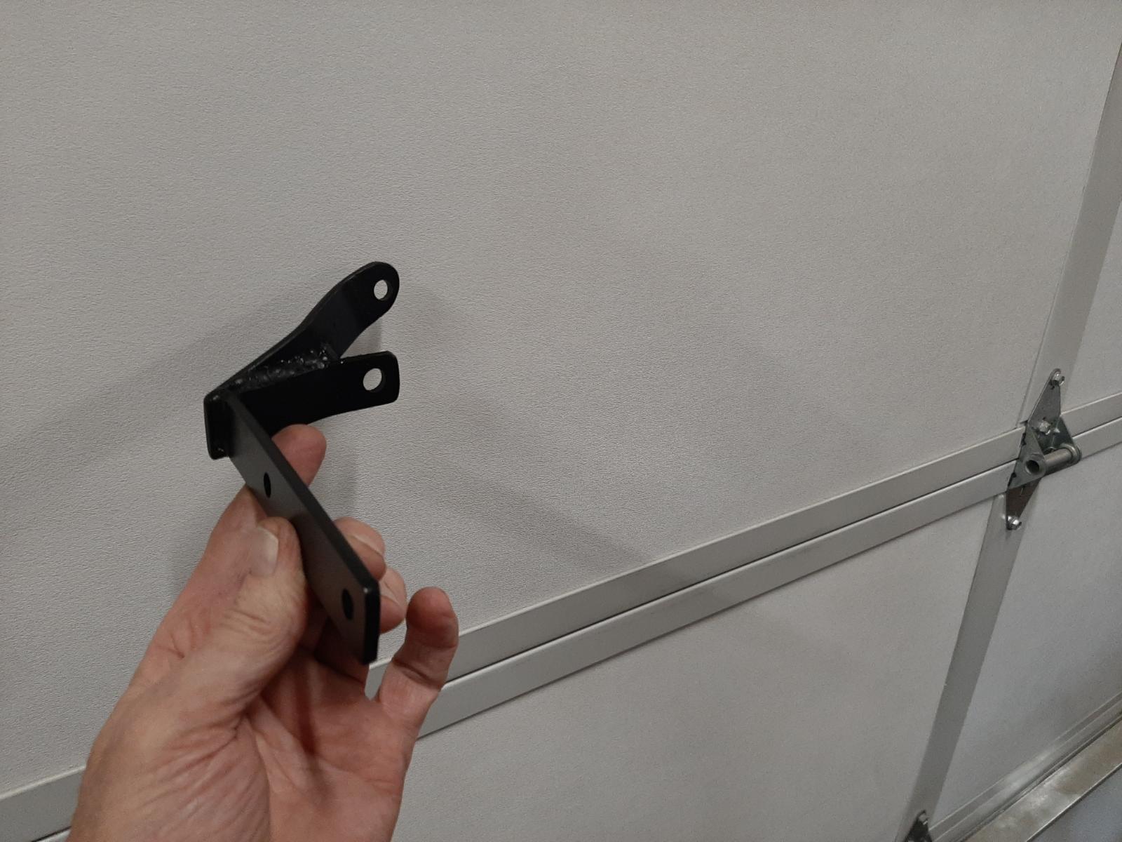
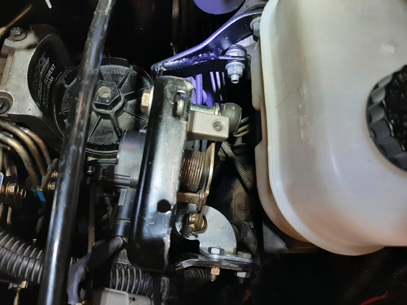
First, and foremost, I was inspired to perform this modification by @Mace (a new member with lots of knowledge) who provided the idea - I never would have thought to do it on my own. I also want to thank him for providing the "how to do it " information as well as a list of parts. Well, I am finished, but I didn't do it the way Mace from Kamloops did it and in no way is my modification any better that what Mace did - in fact, some may prefer his modification over mine. After much of going this way and then that way and then repeating myself, I just finally came to a stand still. So, I stopped working and started thinking about what I really wanted - which was: * I want the engine noise that is being transferred through the throttle cable into the cabin - Gone! * I want the APPS throttle assembly removed from the engine. So, after re-thinking this AGAIN, I thought why not just remove the assembly from the engine and re-mount it elsewhere in the engine compartment? That way, nothing changes: * I keep my fast idle solenoid * I keep the adjustable throttle stop * I keep the 45° sweep of the APPS * I eliminate the transmission of engine noise into the cab. * I get the delicate APPS away from the pulsing, vibrating engine! So, that's what I did. There are no changes inside the cab. I just relocated the complete throttle assembly to a place between the brake master cylinder and the oil dipstick tube. I fabricated a custom mounting bracket and used two existing bolts on the the hydraboost / brake master cylinder unit for mounting the bracket. This photo shows the custom fabricated mount and its new location. Two more sets of bolts and nuts and the throttle assembly is mounted. Everything is easily serviceable. The throttle unit can be unbolted (either from the hydraboost or the APPS mount) with just two fasteners. The unit can be lifted up and laid flat for throttle cable disconnect / replace. The APPS can be removed / installed without removing the throttle assembly. The idle stop and the fast idle can be adjusted with the engine running. The fuel filter is easy to remove / replace. Now for the best news - the noise is gone! Absent! Doesn't matter whether or not my foot is on or off the throttle or if cruise control is engaged or not. I didn't realize it until now, but that rattly noise was always there to some degree at every throttle position - including foot off the throttle. When I turn on the Fast Idle switch now, the tach goes to about 1150 rpm and is steady as a rock (used to float +/- 50 rpm). Shoulda done this about 393,000 miles ago! - John


-
If you are experiencing the noise that I am referring to, you will not need to put your head under the dash. My noise is most noticeable at highway speed and the noise is being directly transmitted through the throttle cable and the throttle pedal acts as a speaker. I can set the cruise control and remove my foot from the throttle and the noise will either subside, or sometimes be worse. Other times its works the opposite way, but it is there to some degree all of the time. Very annoying..., well, actually, not annoying any more! - John
-
I completed my project yesterday. I was successful. Before I go into detail, @Doubletrouble, do you get an obnoxious rattly sound transmitted from the engine to inside the cab via the throttle? My truck has always been that way since new. I have a friend who has a '99 truck with a 6 spd since new and he says his is that way, too. @Mace, was yours that way before you relocated the APPS? Doubletrouble, I'll wait 'til you finish your popcorn..., - John
-
In 2000, I was working in Vehicle Maintenance at the Copper Mountain Ski area in Colorado. We started using Wabasto heaters on our buses. Nothing like opening the doors on a 10°F below zero morning and stepping into an already warm bus. - John
-
I set up my OEM throttle assembly complete with the throttle cable operational for a bench test. It turns out that although the OEM APPS shaft rotates 45°, the actual foot throttle rotation is about 20° due to the different lever length combinations along the way. So, that would be much more in alignment with the replacement bellcrank, which has a 20° sweep. I was overthinking it, as usual. I will now proceed with using the replacement bell crank assembly. - John
-
Thank you, I will give that a try. - John
-
@mace, I am proceeding with my APPS relocate. I have removed all the necessary items. There is a pin that is pressed into a part of the aluminum bracket that I need to remove so I can use the hole for my custom bracket (not made yet). Did you remove this pin, and if so, how did you do it? - John
.JPG.461854f6e0f8a6329bcc040449fb62e8.JPG)
-
So, I ordered the parts for the APPS relocate and the power steering / reservoir and vacuum pump relocate. Some of the parts have arrived and I am going to do the APPS relocate, first. First observation on the new APPS throttle pedal is that the pedal only rotates 20° from stop to stop. The mechanical part of the OEM APPS rotates 45° from stop to stop. I much prefer the 45° for more precise throttle control. Just curious, @Mace - is your new throttle pedal also limited to 20° rotation? I am going to modify the OEM APPS throttle and make it work for three reasons. One (as just mentioned) - the 45° rotation is preferred, two - there is a mechanical low idle and high idle adjustment screw, and three - I already have a functioning custom installed fast-idle solenoid mounted to the hardware. I have already removed all of the throttle associated components under the hood. It certainly does free up some space. Just thought of something, so I am editing this part of my post. I need to check the distance of the throw on the OEM APPS end of the throttle to see if is the same as the distance of throw on other end of the throttle. If so, it would be a 1:1 ratio and the throttle pedal would need to rotate 45° to get full use of the throttle. - John
-
I was thinking that you might find that specific information useful. - John
-
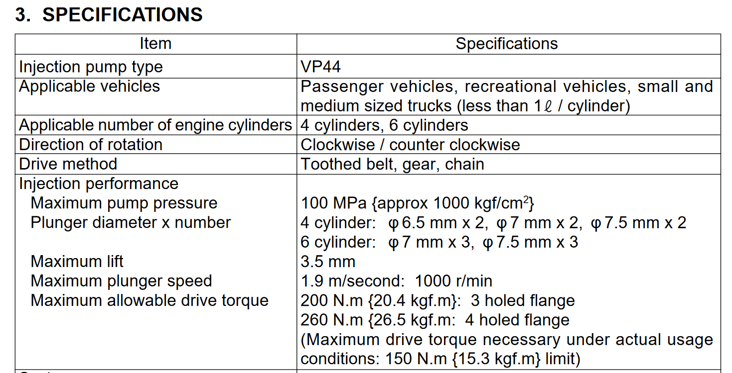
I believe that there are 1,000 mil in a liter. Does this help? I think you can get pretty accurate with the high pressure side of the injection pump, but not so much with the vane pump. Even though the vane pump is fixed displacement, I have never been able to find documentation of volume displaced per one revolution of pump. To further complicate matters, is that the vane pump puts more fuel over the regulating valve at higher rpms that it does at lower rpms - in fact, at low rpms the vane pump may not even put any fuel over the regulating valve - nobody seems to know. I performed return fuel flow tests that showed 19 gph at idle and 28 gph at 2,000 rpm. So, theoretically the the fuel return volume should have more than doubled at 2,000 rpm, but it didn't. So, being that the vane pump is fixed displacement, this would mean that there is lots of fuel passing over the regulating valve when the engine is at 2,000 rpm. How much, who knows? Below are some fuel return flow tests I performed from the VP44 to the fuel tank. The VP44 is an HO pump. For the tests I used a one-gallon oil jug with volume markings at one-quart intervals. I used a helper and started the clock on the 1 quart mark on the jug and stopped the clock on the 3 quart mark on the jug. The total volume returned for each test was .5 gallons of fuel. My truck is a 2002 2500 with a NV5600 transmission. The fuel lines are stock diameter, the fuel filter is the OEM filter inside the filter housing mounted on the engine, and the lift pump is a used frame mounted FASS DRP-02 that probably flows somewhere around 65 GPH - 12 psi @ idle and about 6 psi @ 2,000 rpm. I performed the tests as follows: Test #1: engine at idle, fuel transfer pump operating - .5 gallons pumped in 92 seconds Test #2: engine at idle, fuel transfer pump operating - .5 gallons pumped in 94 seconds Average fuel pumped is .5 gallons in 93 seconds = .3225 gpm rounded to .32 gpm or 19.35 gph Test #3: engine at idle, fuel transfer pump disabled and bypassed - .5 gallons pumped in 93 seconds Test #4: engine at idle, fuel transfer pump disabled and bypassed - .5 gallons pumped in 95 seconds Average fuel pumped is .5 gallons in 94 seconds = .3191 gpm rounded to .32 gpm or 19.35 gph Test #5: engine at 2000 rpm, fuel transfer pump disabled and bypassed - .5 gallons pumped in 64 seconds Fuel pumped is .5 gallons in 64 seconds = .47 gpm or 28.1 gph Return flow tests were done by a couple of guys on the Turbo Diesel Register in April of 2001. There test results were very close to mine. - John
-
This part number is showing gasket only. I did see a pump (no kit) with the part number 4988390, not 290. Is there an actual "kit"? I know - lots of questions. - John
-
Thank you for clearing that up. Those sellers are rather crafty. I think I am going to proceed with this modification. Really appreciate your help. - John
-
Just for clarification. The three photos that you posted of APPS - are they the counterfeit ones, or the good ones? Also, If I am understanding correctly, I can just use my Timbo in the conversion - correct? - John
-
Mace, Thanks for the sharing details on those two mods - very informative and you have definitely caught my attention. I have the very same symptom that you mention regarding the limited turning of the steering wheel with the vehicle stopped. I would be very happy to see that gone forever. Definitely like the idea of continuing to use my Timbo APPS inside the cab. - John
-
Do you recall the approximate cost for the conversion? Also, what is a "WC sensor"? - John
-
Mace, thanks for the quick reply - I will be looking forward to seeing the pictures tomorrow. I have always had engine noise transmitted into the cabin via the throttle cable. Did you have a similar noise before you did the throttle modification? - John
-
Welcome to the site Mace. Some interesting things you have done to your truck. Looks like @IBMobilebeat me to it. I am interested in your APPS delete, as well. I see that you have a 6 speed transmission. Does your electronic pedal have smooth, precise control of the the throttle (important to me with a manual transmission)? I have a 2002 truck - original owner - at 393,000 miles. How many miles / kilometers on your truck? - John
-
I would re-train your left foot to not rest on the clutch pedal. You may have contributed to this noise. There is already light spring pressure from inside the slave cylinder that removes the slack from the pushrod / throw-out fork and maintains zero clearance for the throw-out bearing while the clutch is engaged driving down the road. Any additional force will make the bearing spin at engine rpm 100% of the time. - John
-
Didn't think abut that part - you may be on to something. - John
-
You guys are amazing!
-
I would probably keep driving the truck and continue monitoring the noise. If it truly is the actual bearing that is failing, it will get worse and you would be able to feel the bearing roughness with the clutch pedal engaged. From what you said in your original post, "There's no noise if I coast for a long time with the clutch in either." would indicate that the actual bearing is doing what is supposed to be doing. - John
-
I was one of those many people - thanks for the info. I don't think it is your throw-out bearing - I think it is the contact area between the part of the bearing that contacts the tip of the diaphragm fingers. There is nothing to hold a film of grease there. I think the bearing itself is doing fine. In the "old days", before the common use of hydraulic clutch controls, clutch control was done mechanically. The adjustment on mechanical linkage never allowed the throw-out bearing to contact the diaphragm fingers when the clutch pedal was released. Not so with the hydraulic clutch control. - John


