Tractorman
Yearly Subscription
-
Joined
-
Last visited
Everything posted by Tractorman
-
I checked Rock Auto and I see that they are genuine Bosch OEM injectors. I don't think the problem is injectors. You do need to get this figured out as you don't want your wife to have to spend too much time in a ravine with an old Beetle. John
-
My wife and I will be returning from a local camping trip on Friday, June 6. If your trip to Baker City will put you here after June 6th, you are invited to our house and you could stay in a private camp site with water and electrical hookups. You could then tour the areas that you want to see at your leisure. We would be happy to meet a member of the forum and help out if we can. Think it over - you can private message anytime you want. I also have been turning wrenches most of my life, and have a shop and plenty of tools should they be needed. John
-
They are stock OEM injectors - correct? John
-
Only 128,000 miles on the truck? What year is the truck? The fuel pump relay that I am referring to is for the VP44 injection pump. It supplies power directly to the fuel solenoid inside the VP44. It is labeled "Fuel Pump" or "Fuel Pump Relay" and it is located in the PDC. The OEM lift pumps are not relayed - they receive power directly from the ECM. I am the original owner of my truck. I started having problems with the VP44 (P2016 code) at 65,000 miles. A year later at 87,000 miles, I had the VP44 replaced under warranty. Additionally, a relayed lift pump was fitted into the fuel tank, also covered under warranty. I have since logged over 310,000 miles on the re-manufactured VP44. Also, worth mentioning is that for the last 310,000 miles, lift pump pressure has never been over 12 psi and usually averages about 5-6 psi, so lift pump pressure really has never been causing the problems with the VP44. Assuming your VP44 has failed and you are running the original VP44, there really is / was nothing you were going to be able to do to make your VP44 last longer. There was a lot of misconceptions regarding the VP44 injection pump failures in the early years and those misconceptions have carried on through the years. The lift pump was the least of the problems, or not even a problem at all. Bosch recognized that there were issues with the early VP44's. Some of those were: rotors not de-burred properly during manufacturing resulting in rotor seizure, poor solder connections in the PSG, under-designed diaphragm for absorbing high frequency pulses, metallurgy problems with timing piston / bore, to name a few. The good part is that Bosch corrected all of those issues with many revisions during their VP44 re-manufacturing process. Unfortunately, other re-builders became involved, but did not necessarily follow through with the Bosch updates. That resulted in casting a continued dark shadow over the VP44 injection pump reliability. From an authorized Bosch re-builder, the Bosch re-manufactured pump comes with a new PSG calibrated to the pump. The combined unit is operated on the Bosch 815 test stand for three or four hours of rigorous testing. This is the pump you want to buy. They have proven to be reliable. John
-
Well, dang! Did you get good life out of the pump? Those three codes narrow things down a bit. By chance, did you try swapping the VP44 pump relay with another like relay? Doesn't cost anything to check. John
-
I think he said that he did a road force balance on all of the rear tires. John
-
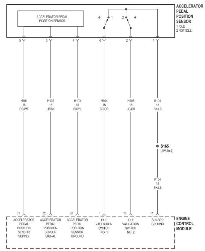
The VP44 trucks were only made from '98.5 - '02. There could be a discrepancy in some wiring colors, but not likely. Just pick a row that looks like the colors match the pinout row and you will know right away whether or not you are on track. For example, if the LB/BK wire APPS signal from the ECM pin #25 was a different color than the diagram, then the wire will be the same color where it connects to pin #3 on APPS connector. Just be patient - it will begin to make sense. John
-
That's always a bit confusing to me, as well. I verify by identifying some of the wire colors on the wire connector side to match them with the pin number. This will confirm the orientation for identifying the correct pin number. John
-
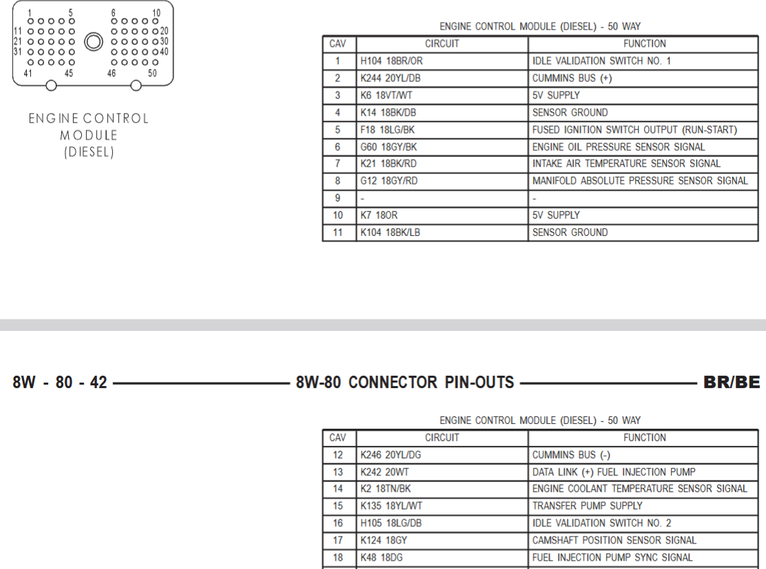
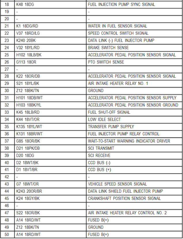
Shown below are the pinouts for the ECM. Perform continuity tests (using the ohmmeter setting) on circuits that you wish to check. Be sure there is NO POWER supplied to any circuit being tested. For example, the APPS communicates only with the ECM. You could perform continuity tests on all of the connecting wires (see bottom photo). John
-
Also, unplug the ECM and check for any pins that may be pushed back. John
-
Ok, I understand. That should rule out a torque converter issue. It does make sense that something changed during the replacement of parts. If I recall, you have to move the throttle assembly to the side in order to access all of the injector lines. Is it possible that the throttle is binding and not letting the throttle fully return? If the throttle does not fully return every time, it is possible that the idle validation switch is not activated in the APPS circuit. It must be activated for the ECM to know to take over idling the engine. Engine idle is controlled by the ECM only - no other inputs. John
-
Don't focus on this. You could be right, but you also could be wrong. Another scenario (mentioned by @Mopar1973Man ) that could cause your issue is a low stall speed transmission torque converter. Larger injectors allow much more fuel to flow, so when the engine comes to idle, the ECM has to cut way back on fuel delivery (not so much with stock injectors). So, things like a low stall speed converter, or engaging the clutch with a manual transmission, can cause idle fluctuations while the ECM tries to correct. John
-
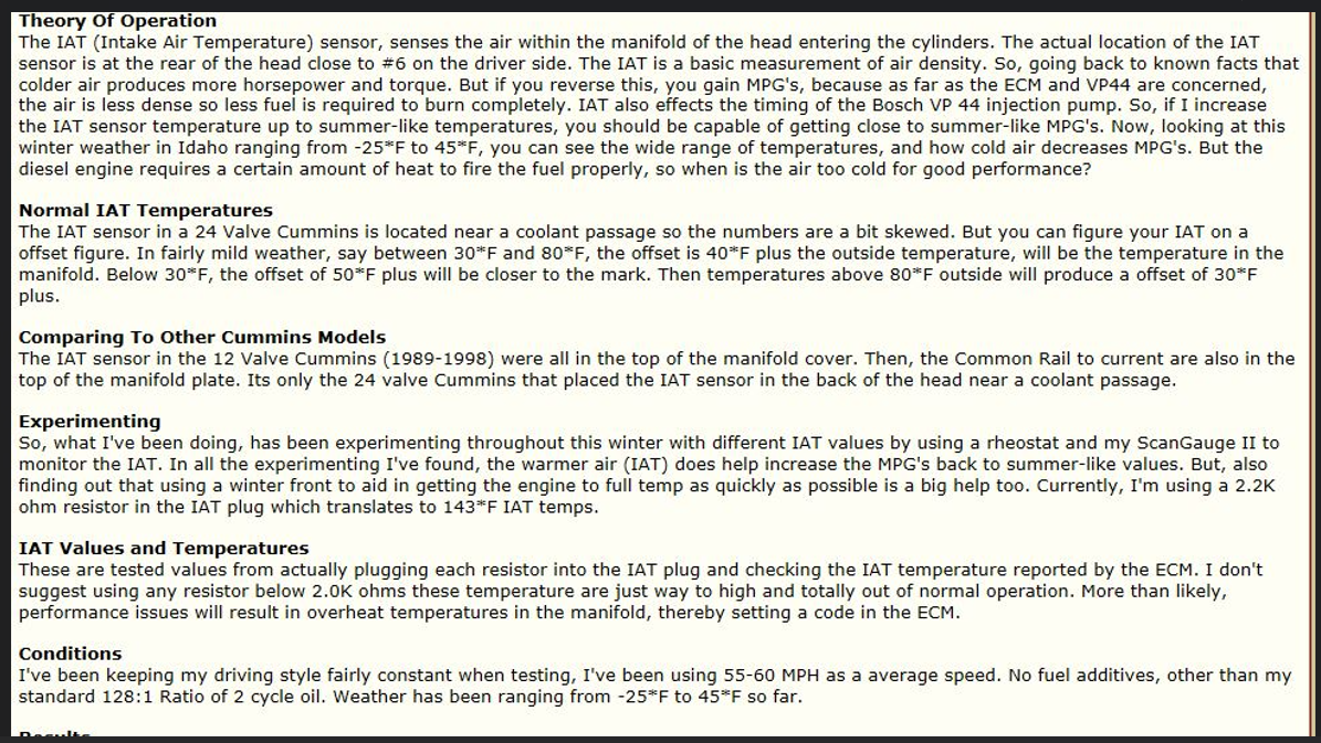
You asked, "What are the values of the potentiometer that you use? I like that idea quite a bit." Back in 2016, I tried a fixed output resistor of abut 2,200 ohms, but it set a code and I didn't have a scanner at the time to read the fooled temperature. So, I just bought a variable resistor and installed it (trial and error) and it worked. Later I purchased an OBDLink and dialed in the temperature of 143°. It is easy to make the modification - just buy a couple of Deutsch 2-pin connectors with pigtails from Amazon for the wiring. John Here are @Mopar1973Man 's observations.
-
I think you are correct. I am basing this on the fact that I am using an IAT fooler (potentiometer) that is adjusted to keep the IAT reading at a constant 143°F. I can tell the ECM responds to the setting because it does not advance the timing aggressively, as it does without the IAT fooler. I don't have the high idle switch on my truck. Maybe it would be worth completely removing the high idle switch to see if the symptoms change. John
-
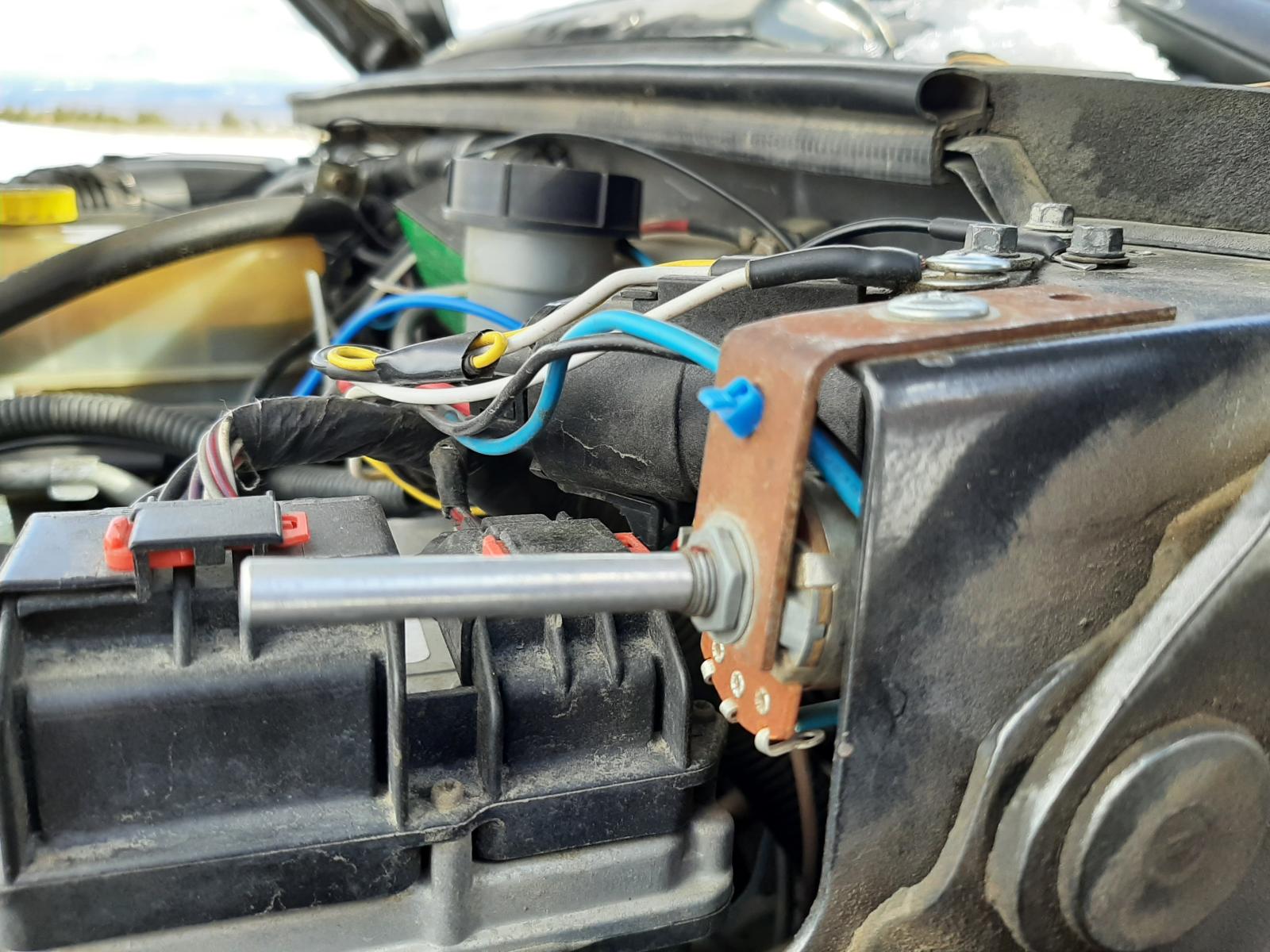
This photo is of a typical 12 valve engine. No crossover tubes. Fuel line are connected directly to the injectors, so injectors can be shimmed. John
-
My guess is that if you change the height of an injector on a 24 valve engine, the connection point of the crossover tube to injector will be misaligned. John
-
That's good news, as well as an inexpensive fix. I should replace my fuel pump relay just because it is the original and has logged almost 400,000 miles. No sense of waiting for it to become a problem - especially, an intermittent problem. Thanks for posting the fix. John
-
Glad to hear that everything worked out and thank you for reporting back. John
-
It may seem like there is no interest here because you are not getting any more responses, but I think that we are at a loss of how to fix the problem. I would focus on the above paragraph since the truck was fine before the tire change. Did you replace all six tires, or just the four on the rear? Did you replace tires and wheels, or just the tires? Did you do any other repairs at the same time? Are the wheels centered on the hubs? John
-
You certainly do good work!! John
-
Were these readings with the P1689 code set or cleared? Were the readings different with the code set and with the code cleared? John
-
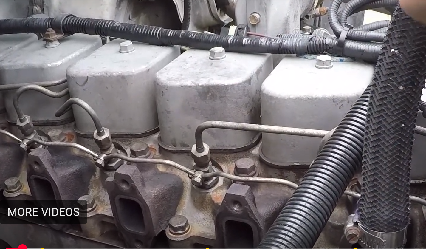
I tend to agree with that conclusion, but I wouldn't rule out a ground issue. Poor grounds can cause irrational behavior and can mess with your mind. Have you tested the CCD circuit (as described below) while you are making changes in the blower motor circuit? It would be interesting to see if CCD voltage readings reflected a change when the "no buss" message showed. John
-
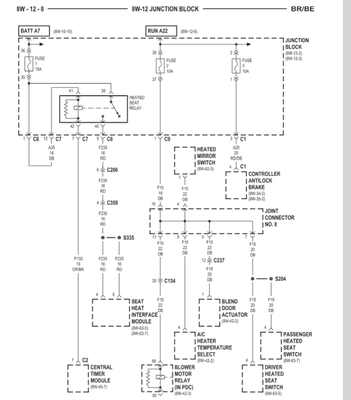
It is only the blower motor relay coil (#85 and #86) that draws from this fuse. That current draw is less than 200 milli-amps. The switch portion of the relay (#30 to #87) carries the full load for the blower motor - #12 40 amp fuse in the PDC. Most likely you have a short circuit to ground downstream of the mirror heater switch / relay that is causing the blown fuse when you activate the mirror heater switch. At least you now know where to begin looking for this problem. Back to the "no buss" message issue - I will have to think about that some more. John
-
Since you mentioned this, I did find a correlation between the heated mirror switch and the blower motor circuit. The 10 amp fuse #2 in the junction block feeds Joint Connector #8 which connects to the mirror heater switch and some other components INCLUDING connection to the coil of the blower motor relay. Was it the #2 fuse in the junction block that blew? John
-
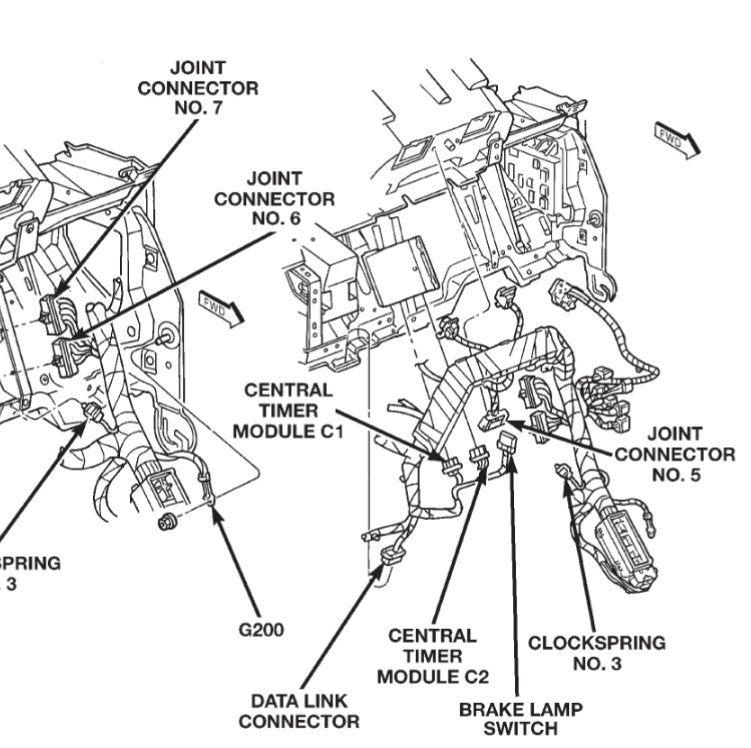
From the FSM, the blower motor and HVAC controls ground at G200 which looks like a stud behind the kick panel. Hopefully, this illustration can help (unless, of course, you have already seen it). John