the7t7
Unpaid Member
-
Joined
-
Last visited
Everything posted by the7t7
-
I'll try the bigger spread to see what it does. I was just trying to keep smoke down in the lower psi/ higher load scenario by setting the max timing a little advance and cutting down on load timing. I bumped up to level 4 once I got level 3 close (essential no smoke except a little gray at initial low psi 30%+ throttle applications from cruise or a stop) and noticed that throttle smoke was only slightly worse and I got only slight haze under medium to hard load. Gradual acceleration still produced no smoke. So I think I'm pretty close. A couple more questions while I got a few of you looking. 1.) I have my boost scaling set to 40 (max?) because the compounds can go higher. I was wondering if I am leaving fuel on the table if say the ecm only recognizes max 35 psi, which would mean the quad would stop adding fuel there. That would leave 5/40 (12.5%) of my tap unused. Not a big thing but is my logic correct? 2.) I think I saw in some earlier quad threads that some people were setting their 0 psi at a certain point and then starting their map at a lower fuel % at 1psi. What was the purpose of this? 3.) If I was to make a tow version of my tune, what setting should I change. I was thinking of cutting back light load timing but didn't know if I needed to do more.
-
It’s usually 0 to about 18 psi where I get smoked under heavier throttle unless I cut back the whole map to starting around 70. When I go as low as 65, I don’t have smoke anywhere. It’s still drivable there but surges a bit under light acceleration. Starting at 70, initial throttle smoke is minimal and there really isn’t any much anywhere else, so a good compromise. I’ve essentially been sorting the tuning like you've discribed. I tried finding a starting psi using the setting1 method but that only got me a range to start with. Honestly I could not tell much difference in smoke below the psi where it changed from black to gray. It was all just shades of grey below about 78 psi. I suppose doing data logs would help but I really don’t have the time to get that detailed. I will try bumping up the levels to iron out the curve a little better but I’ve got a good start now. I was just being a little ocd about smoke. Thanks for the help. At least I know I’m heading in the right direction.
-
Thanks I’ll try the new numbers. My injectors are DAP 7x.0105 VOC. As for your other questions, I’ve only been messing with level 3 since my issues seem only to be initial smoke on medium to heavy throttle application while cruising at low psi or when accelerating from a stop. Normal or gradual acceleration generally produces no smoke through all psi settings. I was just wondering if I was missing something with regard to timing since it seems like I have some room for more fuel at lower psi (less than say 20 psi) because under steady acceleration (once turbos are caught up), I have no haze at all. However, when I do try to raise fuel below 25 psi, I get more smoke from throttle application that doesn’t really improve when I add timing. It’s peppier but smokier. It still pretty clean under gradual acceleration starting at 75 vs 70. As for the upper psi fueling, the reason I ramp up the fuel after 24-27 psi is because thats when it feels like both turbos start really working well together. No matter what fuel map or timing setting I have tried, the truck always seems to start pulling hard around 25 psi. I can go well into the 50s with my set up (I have arp head studs).
-
I've been messing with my daily tune and have a few questions (elev 3800ft). I have a compound turbo setup with 175hp 7x011 voc injectors. I am tuning for smoke mostly. I've got most of the smoke out of my tune except for start up (I'll ask about that later) and low psi, mid to high load situations while cruising from town speeds to sub highway speeds. One thing that's a little troubling is that my current can bus fueling is way below what the tune builder suggests. I've started as high as 75, however, I get pretty decent clouds of dark drey smoke when I accelerate with more than 30-40% throttle from cruise. I've dropped the load timing down to 1* and gone as high as 17* on the 1500 max timing but its not really clean enough for me. We have a lot of roundabouts in Bend and starting at 75% blows smoke at the pedestrians accelerating into or out of the them. It's not black smoke and the truck is more responsive at that level, though. Below is my best tune at controlling smoke. I feel I could go a little higher on low psi fuel since steady throttle while cruising around and gradual accelerations produce no smoke when use a 75% starting can bus map. I just can't tune out the mid to heavy acceleration smoke dump when I need to get going at that starting point. Second question relates to cold and even warmish 1st starts of the day. I've read that the quad doesn't take over until after 1000 rpm and some throttle at a certain IAT. Has any progress been made helping the quad fuel during this scenario? I get pretty large amounts of gray smoke at start up. Its especially annoying if the truck was in the garage overnight. I try to put it in gear as quick as I can but I get that large surge/stumble that others have complained about. If its fairly cold and I try to move too soon it can die. Is there a way to fool the ecm into thinking it's warm with some sensor resistors, and switchable relays etc? Thanks. Here is my tune:
-
Yes that’s the plan plus a bit more. My truck had fried it’s second ecm and nothing obvious was the culprit. (I have a recent post about the details). I had already done the w-t mod. So out came the wiring harness and the vp44. The pump was working but since I had to do a tappet cover gasket, the pump had to come out. I sent it to Oregon Fuel Injection to test. Ended up it had a rare issue where it had a bad chip in the psg with codes there but still continued to work. The wiring harness was fine, so I think the psg was the culprit and took out the ecm on the data link wires. While everything is apart, I’m improving the crappy factory splices in the harness and putting new connectors on all the weathered pdc and engine grounds and battery cables.
-
Those are some good opinions and that’s what I asked for. I’m leaning towards keeping it on the engine. I don’t think the extra distance would cause any issues but I can’t be sure. Since I was just hunting down an ecm failure issue, I don’t want to add any more variables to sort through in case it doesn’t start with the new ecm and vp44 (which I’m mostly sure is the culprit since old one had a bad psg). It would add around 50 new splices that could be a source for failure. I did add some rubber bushings and some reflective insulation on back side of new ecm just to help a little with heat and vibration.
-
Can anyone think of a reason why I shouldn’t move my ecm to inside the cab or the firewall? My engine harness is out of the truck getting improvements and I have a second wiring harness that I was using to help diagnose my ecm issue. I realized I could use the second harness to extend the length of my current one. There is room on the firewall under the brake master cylinder or in the cab under passenger dash. Only alterations besides splicing I can think of is I would have to make more twisted pairs of the water in fuel(not used) and oil pressure sensor wires since they are the shortest and exit right by ecm. There are also 2 shielded pairs (vp44 and Cummins bus). The Cummins bus (which the Quad uses) l wouldn’t have to extend. It would just end up in a different place. For the vp44 pair, I could just wire both harnesses wires end to end, and run one shield power wire to both shields. Only worry is if ecm is expecting a resistance range on that wire, since increasing the shield length would make the resistance go up. Ecm on the engine is obviously not the best place.
-
Auto Computer Specialists finally got back to me about their diagnosis of my old ecm; which was that they couldn’t diagnose it. They said they couldn’t establish communication with the unit and therefore couldn’t help. And for that, I had to pay $150. I’m definitely annoyed at that answer. Last time they gave me a photo of the damaged area on the board. They could have done that this time, compared it to my old one, and let me know what that could mean. They could also have told me what operations any damaged area of the board dealt with. How do I know they even really did anything? Anyway, since I have a good candidate for the failed ecm in the bad chip in my vp44’s psg, I’m going to wind this thread down. I know I was going to post pics of my harness mods but I thought I would make a new post about that related to electrical and harness restoration and maybe show some differences between the 99 harness and my 98.5. I also came across an interesting alternator alternative when I took mine in to gets tested. I can post more details in the new thread but basically a local company in Redmond Oregon (Hagemeister Enterprise’s, INC) builds a 1 wire upgraded Bosch unit for these trucks that takes the PCM out of the equation. This keeps the pcm from possibly getting damaged by the alternator or one on the batteries getting overcharged. I know about Mopar1973man’s article dealing with protecting the pcm with a fuse on the blue wire. This alternator is an different approach. You put a resistor between the blue and green wires and don’t connect them to the alternator to fool the pcm into thinking it’s there. The Bosch unit is then regulated on board. You get a bump in amps to 135 and a better base unit than a rebuild (which is what I had). The pcm does a good job regulating voltage in general. I talked to another electronics guy here in bend and he said that he’s seen a guy come in with 18 year old dodge factory batteries that finally needed replacing. I’m just wary of the increasing cost of pcms a and ecms and that if they go down, your truck is down.
-
Yes they did. However, it’s around half the price without any warranty, which would be nice to have. I think I agree about the standard pump. I’ve already got a decent tune for my injectors, I don’t really need more fuel.
-
So I’ve never been so happy to find out something’s broke and going to cost $1500-2000. Got news back from Oregon Injection that the psg in my pump has a bad chip. It passes the flow tests and code tests but didn’t pass the psg test. So it worked but could easily be the issue that’s making my ecm’s fail. So I need a new injection pump. Since I have compounds and 200hp injectors they suggested their hot rod pump. It flows much better and has a new psg. My concern is they do have a warning on their site that says “Note: may cause minor surging or rough run at light load up to 1500 RPM if using performance injectors (above +40).” Any one have any thoughts on this or experience with a hot rod pump, injectors and quad running issues? I still want it to be daily drivable. I need to decide tomorrow. Price is reasonable compared to Bluechips performance pumps. Or should I just get a standard rebuild.
-
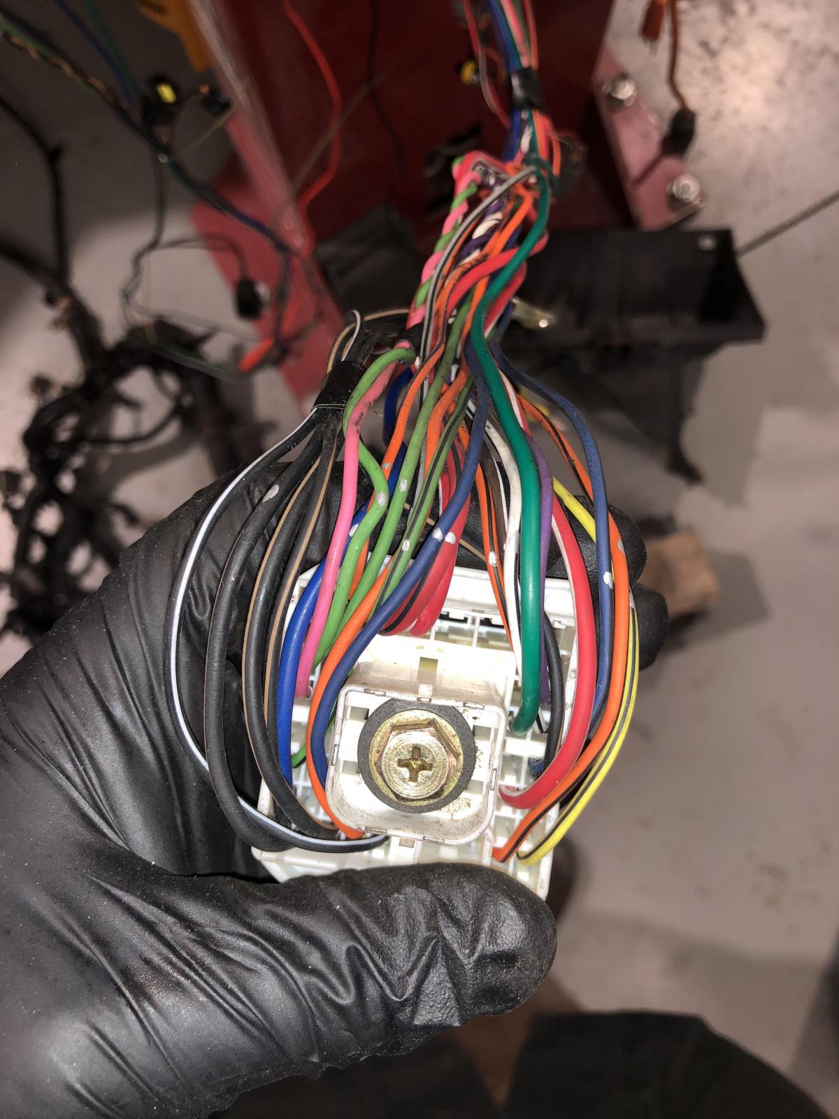
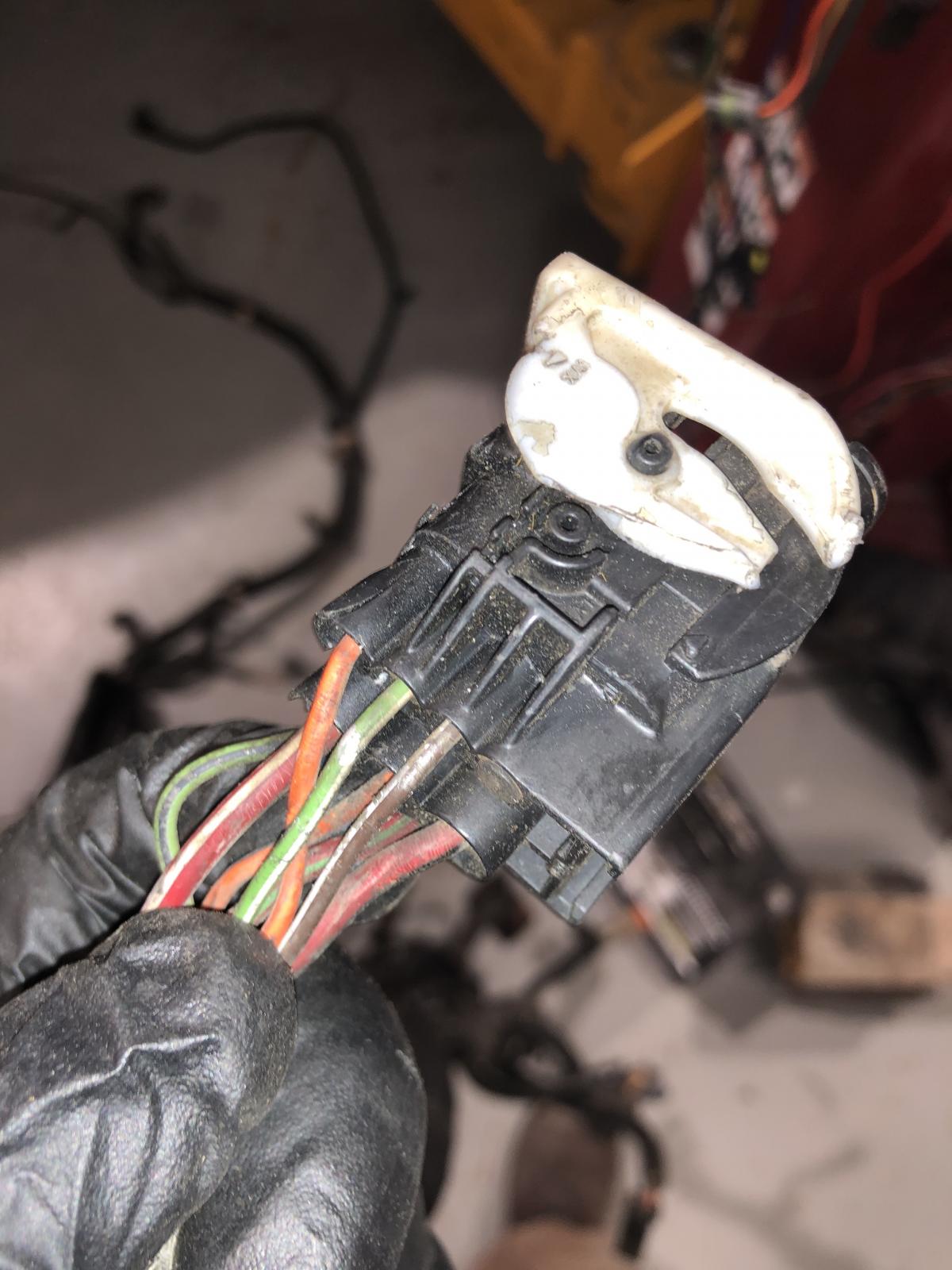
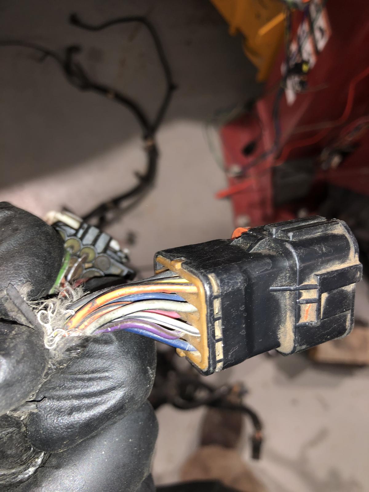
ACS said they are working on my old ecm now and they should have some info for me in the next day or so. I sent my vp44 to Oregon fuel injection since they are fairly close and they are testing it. The 99 wiring harness arrived and I only had time to give it a quick look. An obvious difference is that my PDC connection is different or the 99 has 2 connectors before the PDC connector. My connector is the first pic. The 99 has the 2 connectors in 2nd and 3rd pics. Does anyone know if this is normal i.e. is the harness I was sent actually a 99. The rest looks normal. Another difference is that I have 25 wires going into my pdc and the 99 has only 20. my extra wires mostly seem to be grounds. I’ll give it a more detailed look tomorrow. I haven’t forgotten about posting pics of my harness mods. I’ve just been waiting on the 99 harness to compare it to and doing other work on the truck.
-
I'm posting a little update since I'm still waiting on ecm diagnosis and its been a few days. I ended up removing the engine/ecm harness because it would always bother me that I didn't check it. In the interest of thoroughly checking everything, I'm also going to remove the vp44 and send it off to Oregon Injection (its one of theirs) and have them go through it, since I don't really know how many miles are on it. I'll do the tappet cover gasket at this time since its weeping a little. One of the things that make me think I have a weird early truck is that I have the 12V tappet cover with the crankcase vent on it. I do not have the crank case vent on the timing cover. I looked on the internet and couldn't really find any mention of this for 98.5s so not sure if its normal or not. On a side note, does anyone know the front crankcase breather would screw to my cover on the vp44 inspection hole? I could actually use more cranky ventilation since I have a compound turbo set up. I didn't have any leaks until I ran it on the dyno. Now I have front crank seal and tappet cover leaks. I'm thinking extra pressure from high horsepower dyno runs helped accelerate those leaks. I also noticed that I had a bunch of blow by when I did those runs when normally I don't have much. Back to wiring. I also purchased a used 99 harness that has a couple busted plugs for $120 on eBay so I can compare it to mine. I should get this next week sometime. I have noticed a few things about my wiring that's different than what the 98 manual says and what the 99 mopar1973man diagrams say. For instance, my truck originally had the PCM grounds go to one of those passenger side ground plugs and then over to the engine (through alternator harness) to the ground at the front of the engine. When I did the wt-mod, I just ended them at the passenger side battery. The 98 manual says they go over the top firewall harness, through those 3 plugs high on the drive'r side, through the PDC and down to G100 under the driver's battery. My truck has those wires but they dead end at that high firewall plug and don't continue on to the PCM that way. If anyone is interested, I can take some photos of the harness (and my splice mods) since it's all cleaned up and ready to be rewrapped. Just waiting for ebay one for comparison.
-
Yes, they are apparently off for the holidays. I did get an email today that said they would get to it after the Holidays. I don’t know if that’s this Monday or Friday the 2nd or the next Monday. I do hope they can narrow it down for me. I did spend a bunch of hours today ohm testing every single ecm pin out to its source as well as further to common grounds and shared power sources. The cam sensor and crankcase sensor were particularly hard to get at. I didn’t check every single ccd bus connection but I did a few. I only found one bad connection. It was an ecm power connection to one of the grid heater relays. The connector itself had 40 ohms resistance through it even after I ran some sand paper inside it. The wire right after the connector showed low resistance. I’ll splice in another connector. I may even have an old solenoid connector that I can use, but if not, a ring connector will work. Probably not the source of my failed ecm. If it did anything, I believe that particular grid heater wouldn’t start. Only thing I can think of left is an intermittent short that happens while moving ie vibration or abrasion. Removing the wiring harness and going through it might find something. Not sure if I should do that or wait for for results of old ecm test. I also need to do a front crank seal so might do that while I wait for results.
-
What’s so annoying about electrical problems to me is that after you check the obvious things, everything after that is ridiculously time consuming for someone who isn’t an electrical engineer. At this point I’m checking less common possibilities like connector failure or relay performance or intermittent scenarios. I spend most of my time trying to understand the wiring diagrams. It doesn’t help that my truck is a 98 and the first year of the 24v/vp44 and that the factory manual has supplements that add or replace the original diagrams. I have already found errors and inconsistencies between my truck and the manual, and the supplement and the regular diagrams, which makes it extra confusing. There is also slight differences between my 98 and it’s factory wiring diagram and the 1999 moparman wiring. For instance, some of the colors are wrong and some ground locations aren’t consistent. I also have a sneaking feeling that my truck is a very early 98.5 and isn’t exactly the same as later 98s or 99s. It was an auction truck at a used dealer with 160k miles so I have no idea about it’s history. At least it’s was stock with no mods other than a Fass factory location replacement lift pump (since upgraded to titanium) and an Oregon injection vp44. Anyway lunch is over, so back at it.
-
Not sure if I understand what you mean here. I believe I was doing this when I was looking for leaks in the pdc. However, I wasn’t checking voltage, since everything is disconnected from the battery now, and I have no ecm yet. I was checking resistance with one lead on the pdc positive supply side of the circuit in question and the other on body ground. Generally, the meter should show “open” on all circuits unless there is a short to ground especially with everything off. As I understand it, In resistance mode, the meter sends out a small amount of current through one lead and measures what gets returned through the other. I think most power gets used up powering whatever that circuit is for. Even with everything off, though, some circuits will show resistance and therefore a connection to ground if those circuits include resistors or elements like light bulbs, which are essentially resistors which shed light light when grounded. If I were measuring voltage, I think I would need the circuit powered to measure something like voltage drop. I actually got a good chuckle out of your emoji conversation with dieselfuture. I was actually going to make a joke like “jeez, you guys should get a room” but I’ve gotten in trouble with my sense of humor before, so I restrained myself. I’m not giving up yet. I spent some time yesterday checking the fuel pump relay under load and heat (like with a heat gun and It worked ok) and pulling joint connector 1 and 2 to see if they weren’t damaged. I just didn’t find anything interesting. I’m going to recheck the ecm wiring today and if I don’t find anything maybe pull the harness to check the whole thing. Thanks for all the suggestions and help. Even if they are off topic, it keeps me thinking bout it.
-
I did ask them to test my old one. I think the holidays are slowing them down. I’ll check back with them end of week or Monday.
-
I rechecked the pdc grounds and they weren’t as bad as I thought. They are a little corroded but when I put the meter clip on bare metal right beside the grounds and the other clip on joint connector 1, resistance was fine. So I don’t think it’s those grounds. I did thoroughly check the fuel pump relay for resistance and voltage drop when triggered and compared those numbers to the horn relay. The fuel pump relay works properly but it did heat up more than the horn relay and had slightly more resistance when hot across pins 30 and 87 when triggered(@1.5 ohms). That should make the voltage less at the injection pump but I don’t think it’s enough to cause problems, unless the heating up gets worse with time. For anyone that’s interested, I did trace the the small current leak to ground from the pdc + supply. I pulled every fuse and relay (power too) and disconnected the big harness block connector at the front. I then measured resistance from the b+ bar by the 140 amp fuse to the pdc ground. Of course at this point it was an open circuit. I then inserted a fuse or relay one at a time in every position and watched the meter. All circuits were open except for Fuse 1 (cab fuse panel), fuse 11(Abs), and fuse B (hazard). I forget the numbers, but hey were between 22k and 500k ohms. I then traced the cabin fuse panel leak to fuse 12 and 13 which are a lot of things like a bunch of lamps, data link, and the integrated electric module. My guess would be bulbs for the resistance to ground here. Abs, I didn’t explore. The hazard circuit has the flasher module which has relays built in and possibly resistors so possibly resistance there. None of these circuits have anything to do with the ecm so a dead end for possible ecm failure sources. I can’t really do much more. I’ve found some possibilities but nothing definitive. Not sure if I want to risk the new ecm on a new fuel pump relay and some better grounds. I’m not sure if anyone is still following this. I don’t think my long winded posts are helping but it has helped me to write it all out. Maybe it will help someone else who flails as badly as I do with wiring.
-
I will check that the Fass is moving fuel properly but I suspect it is. I jumped the relay as well as the vp44 and got the truck to idle. I have a feeling it’s the fuel pump relay ground (85). My 98 factory manual supplement says it grounds to G102, whose location is “L fender shroud RWAL”. This ground is not shown in any location figures. I’m assuming RWAL means rear wheel antilock. I do have an unattached ground in that area that connects directly to Joint Connector 1, which shares grounds with those that go to G100, the PDC ground at the forward fender below the battery. Interestingly the 99 moparman diagram says it grounds to G100. Either way the ground there is corroded and showing 4 ohms from JC1. I would guess this would make the fuel pump relay trigger signal (86) from the ecm be unstable and cause the vp44 power to be intermittent. Would this be enough to damage the ecm? I will for sure clean those grounds up. I think I’ll also run a wire from G100 to the B- in a similar way that the vp44/ecm grounds got a B- connector in the W-T mod. Let me know what you guys think. Thanks.
-
A bit of an update. I was saving the pdc grounds for later since I have to pull the battery box to really get to them easily and whenever I checked other grounds they were always good. All the ground wires from Joint connector 1 to the PDC ground under battery came in at around 4 ohms so those aren’t very good. Not sure if that’s enough to fry an ECM. There was also a ground from Joint 1 to just beside the Antilock brakes controller that wasn’t hooked up. Since a bunch of circuits share the pdc ground, I’ll have to delve deeper into those Also spoke to Doug at Bluechip Diesel. He hasn’t heard of a VP44 frying an ecm because of bad PSG connections without throwing a code. This was the same as what Oregon Injection said as well.
-
Batteries were disconnected. I put one lead of the tester (set on resistance) on the plate after the 140amp fuse (where power enters the pdc) and the other on the fused side of the fuse no 3 (fuel pump) without the fuse in it. So it should have been an open circuit. Somehow some small amount of current was getting through the wiring downstream of that fuse back to the b+ side of the pdc. Downstream of that fuse is everything connected in joint number 2 (white bar) in the pdc including fuel relay and a bunch of other relays I think. I did manage to pull apart the pdc and didn’t see any corrosion or melted plastic. I did notice that not all the connections in joint no2 had continuity. There are 3 solid green wires (one of which goes to the wiper motor relay pin 87a) that had continuity for a second and then went to fluctuating resistance in the kohms range. That’s as far as I’ve gotten today. I have a feeling I’m not getting something simple related to resistor relay wiring. But I’ll keep looking, specifically at everything that goes through joint unless someone tells me different.
-
I may have found something while checking b+ line through 20 amp fuse in pdc. While figuring out which blade of the fuse was the b+ side I noticed I had some very high (fluctuating million ohms) resistance between b+ and the open side blade. I let the tester sit there and it gradually decreased and eventually settled on 30k ohms. there shouldn’t be connection between power b+ side of pdc and the fused side right? This suggests to me that I have a short somewhere in the pdc wiring. I pulled every fuse and relay from the pdc and watched the meter thinking this might help me narrow down where the short was but it held pretty steady at 30k ohms. So unless someone tells me this is normal then looks like I have to pull the pdc and check it.
-
Yes, but it probably is something with the truck since I’ve had 2 fail in a similar way with different tuners and before and after w-t mod. I have tested every wire I can get at reasonably easy short of pulling the harness and taking apart the pdc. Only thing I can think of is that I am getting a short that happens under driving conditions that doesn’t show up in static testing or that something is failing intermittently in the psg on the vp44 itself.
-
I’ve checked all the wires to and from the ecm, vp44 connector, pdc, and lift pump. Everything checks out with less than 0.4 ohms. I’ve also checked the fuel pump relay in the pdc and it shows 73 ohms across the trigger connections (85 and 86) which is the same as all of the other relays in the pdc. The only thing I can think of is that the vp44 shorts intermittently somehow over the data, bus or power leads and eventually kills the ecm all while not throwing a code. BTW after first ecm failed, I thought problem was fixed and put it on the Dyno. DPS compound kit and my Quadzilla tune put up 620hp and 1250 ftlbs. So vp44 could supply the fuel, however ecm failed again after about 100 miles. So I’m not really confident that replacing vp44 will solve problem and not really willing to chance $999 ecm on a guess. Would Blue Chip Diesel or Oregon Fuel Injection (current pump) be able to tell me if I sent in my vp44?.
-
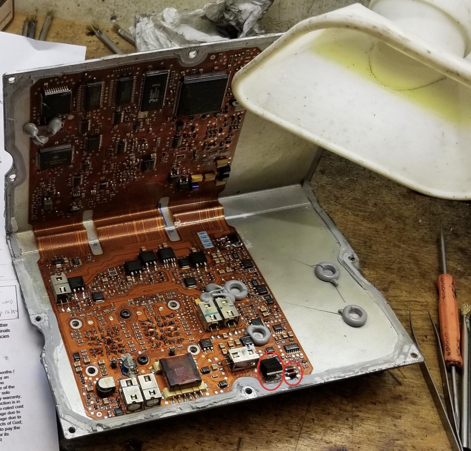
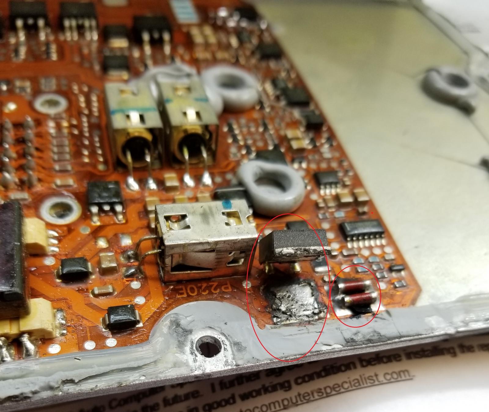
This is where on the ECM it failed on the first failure. Don't have the report back on this last one yet. Anyone know what the circled parts relate to on the ecm?
-
2nd ecm was just exchanged for a remanufactured one, so no diagnosis. But first one can back with this explanation.... Our findings: ECM(engine control module).. unit was DOA (dead on arrival), based on recovery file from cummin they units communication was taken out by altering of our factory programming & low voltage from trying to program.. upon recovery data info was corrupt unit unable to save. Prior to installing repaired unit: a problem still lies in vehicle (it keeps taking out the injectors ). Battery & terminal must be changed....... When the first one happened I was running a Smarty with command module and custom tunes. Now I’m running a Quadzilla. However they both failed within about 500 miles of each other. I was having trouble communicating completely with the smarty and couldn’t figure that out (after a bunch of posts here too). So I switched to the Quad and did the W-T mod, check all the wires between ecm, pcm, and obdII and thought that would solve the problem. I didn’t check vp44 and lift pump wires then but have now and everything seem good. Actually just looking at 99 wiring diagram shows pin 44 going to vp44 connector as a non numbered 9th connection. I have the normal 7 pins in the 8 pin plug. 98.5 and it seemed to struggle and stumble (probably lift pump first) driving around in town and then died completely (then no vp44). My testing after both ecm failures revealed working pumps but no communication with ecm. Further looking at diagrams shows that the "datalink shield" is something that goes around the yellow/pnk datalink ecm wire going to the vp44 and comes from the ecm at pin 44 and attaches at S170. My 1998 factory manual doesn't show a splice 170. I'm going to check the ecm plug to see if I have a line coming out of pin 44 (should have done this before) and if there check further down the vp44 harness to see if I can find the splice. .....Well I have the datalink shield and its a thick casing around the datalink wire shortly after exiting the vp 44 plug. It disappears down into the large wiring harness. I don't think that's my problem then unless its not functioning but I wouldn't know how to test that.