Jump to content
Mopar1973Man.Com LLC
  • Welcome To Mopar1973Man.Com LLC

    We are a privately owned support forum for the Dodge Ram Cummins Diesels. All information is free to read for everyone. To interact or ask questions you must have a subscription plan to enable all other features beyond reading. Please go over to the Subscription Page and pick out a plan that fits you best. At any time you wish to cancel the subscription please go back over to the Subscription Page and hit the Cancel button and your subscription will be stopped. All subscriptions are auto-renewing. 

P1694 and P1698, Diag help


Recommended Posts

Hey,


ive got a 2001.5 2500, 6-speed truck.


intermittently my tach/oil press/water temp gauges will stop working. Typically when this happens my engine also has a quick “kick” to it like it shuts off and jumps right back on. I never get the “nobus” message on my cluster.


if I check my codes I have p1693, p1694, p1698. Also randomly a p0501 code and ABS light.


I replaced my ECM for this issue 1-2 years ago but it didn’t change anything, but I used a reman one so not sure if it’s quality. The issue never went away though.


was hoping someone could help guide me through what wiring to check, or really just help me determine what my issue is.


I believe I’ve monitored my RPM with my zedge before and when my tach is dead the RPM still works on there as does Oil Pressure, but the Water Temp just stays in one spot until the gauge comes back to life on the dash.


any help is very appreciated, oh and I have no access to a DRB3

Link to comment
Share on other sites

So I’ve gone through the diagnostic list to find that it’s saying for both of these codes I’m basically looking for an issue on the CCD bus. So I’m checking Pin 40 and 41 from ECM to DLC for open or high resistance, pin 30 and 28 at PCM C3 connector to DLC for open or high resistance, Pin 31 at PCM C1 for resistance to ground, and pin 30 at ECM for resistance to ground.


is this all I need to be looking at? Only the CCD circuit for both these modules?

Link to comment
Share on other sites

On my way to work this morning I decided to double check. When my tach dies I can still get my RPMs from my edge CTS. Not sure what that means but it seems weird that the RPM is making it to the DLC but not my cluster somehow.

Link to comment
Share on other sites

Yea I plan on checking that voltage at the DLC after work. If I don’t see that voltage what would the next step be? Unplug modules on the CCD bus until it goes back to normal? Or just continue with the resistance checking from DLC to PCM and ECM pins?


do you think it’s going to be a wiring issue rather than a module? Any chance it’s my cluster?

Link to comment
Share on other sites

  • Owner

Normal you can remove different modules that could affect the voltage.


Modules that can't be removed...

  • PCM - This is source of the CCD network.
  • ECM - This is the secondary computer.
  • Gauge Cluster - This creates the bias voltage. 

All other modules are optional and can be removed. 

  • Central timer
  • Radio (Stock OEM)
  • Air Bag Module
  • ABS Module
  • Overhead Trip Computer

Causes of failures and errors.

  • Bus Shorted to Battery
  • Bus Shorted to 5 Volts
  • Bus Shorted to Ground
  • Bus (+) Shorted to Bus (–)
  • Bus (–) and Bus (+) Open
  • Bus (+) Open
  • Bus (–) Open
  • No Bus Bias
  • Bus Bias Level Too High
  • Bus Bias Level Too Low
  • No Bus Termination
  • Not Receiving Bus Messages Correctly


image.png


Remove a module and check the voltage on the bus to see if it returns. If not you didn't find it. 

Link to comment
Share on other sites

Alright hopefully get a chance to go thru it a bit today, humidity is like 100% tho so we’ll see if I feel like working in this stuff


really hope I can get this solved, I’ll feel much better about finally doing the mods I want to do if I know everything works first

Link to comment
Share on other sites

When I was playing around with a spare ecm I had same thing happen, lost tach on the dash but was still seeing it on my quad. I was told that the pcm needs fixing but I knew that I didn't have this problem before I swapped the ECM so I put my original one back in and no more problems.

I don't know if I had lose connection on ecm or something is wrong with it inside, it ran perfectly fine other then loosing tach signal. 

I would do the WT mod and check alternator for AC noise, check all other grounds you can think of. 

All these talks about chasing wires and very rare it's any of it (unless it's one of the splices that WT mod covers), most of the time it's grounds and ac noise, and sometimes failed ecms because of bad grounds and ac noise that been slowly burning up the modules. This is my opinion, it's still worth checking what is suggested by others, never know. WT mod is needed on our trucks and easy to do, same with ac noise it needs to be checked once in a while. There are other ground splices that need attention, but WT covers the important ones that cause most issues.

Link to comment
Share on other sites

Yea wish I had a spare ecm laying around but already threw $1000 at this ecm which didn’t change anything, and I’m not sure if I’d need to program a used one as the info on that topic seems all over the place online.


How would I test my alternators AC output?


the ground wire mod, if needed I should be able to detect when testing the ECM ground. Worst case I’ll do the ground portion of it, not really trying to mess with moving my alternator wire and adding on a new circuit breaker etc. 

Found moparmans video for testing AC noise from alternator, I’ll test that later as well

Link to comment
Share on other sites

  • Owner
22 hours ago, teknic said:

How would I test my alternators AC output?


Quality DVM like Fluke or similar that can measure small AC voltages. Red probe to the alternator charge stud and the black to clean block metal is best or the negative on the passenger battery. 


22 hours ago, teknic said:

Worst case I’ll do the ground portion of it, not really trying to mess with moving my alternator wire and adding on a new circuit breaker etc. 


You really need to. The alternator lead is paired right next to the ECM ground and VP44 ground so when AC noise is created the noise jumps right into the ground leads and pollutes the ground signals to the ECM. This is a required mod. The alternator charge lead is move solely to the passenger battery and the ECM ground are to the gear case and the driver side battery. No longer an issue after the mod. Dropped me from 55-60 mV AC to mere 9-11 mV AC after I was done which is acceptable. 

Link to comment
Share on other sites

2 hours ago, Mopar1973Man said:

You really need to. The alternator lead is paired right next to the ECM ground and VP44 ground so when AC noise is created the noise jumps right into the ground leads and pollutes the ground signals to the ECM. This is a required mod. The alternator charge lead is move solely to the passenger battery and the ECM ground are to the gear case and the driver side battery. No longer an issue after the mod. Dropped me from 55-60 mV AC to mere 9-11 mV AC after I was done which is acceptable. 


Where would I put the 150A circuit breaker? Just between the new alternator to passenger battery wire?


haven’t had a chance to check things out, tweaked my back a bit and combined with this 94 deg 100% humidity weather I can’t convince myself to work on the truck atm.


but I’m compiling all this stuff to check/do once the weather breaks

Link to comment
Share on other sites

  • Owner

When I did mine I pull the entire charge lead out and re-routed to the passenger battery. The circuit breaker I put on the firewall side of the battery tray. The entire cable was completely re-used. The ground side I salvage the plug on the passenger side and made a new jumper from the driver side battery to the gear case. 


Link to comment
Share on other sites

Ok first chance to look at stuff. For starts I’m using a Fluke 88V which I know is balls on accurate, I regularly use it to trace amperage draws and such at work (mechanic)


measure from Alternator stud to negative terminal (on both batteries) .030-.040 AC voltage. Watching dashboard as tach died and came back there seems to be no correlation towards higher AC turning tach off. While monitoring the AC voltage though the tach issue seemed to occur often but that could be random


2nd Test- my tach is dead during this test, Key On Engine off. Ground to OBD2 Pin 3 - 2.49V, Ground to OBD Pin 11 - 2.46V


checking resistance across Pin 3 and 11 of OBD is showing 60.6 ohms, with minor fluctuations (key off, batteries connected). Biggest fluctuation was dropping to 52 ohm very fast before going to 60 again 


think this means the network is good voltage-wise. Resistance I’m not sure of. I’m open to opinions tho.


3rd Test - With tach dead perform cluster test, everything functions properly. All needles work. Only codes showing on cluster are P1694 and P1693, p1698 only shows on my Edge unit I guess


4th Test - Pin 30 ECM to Drivers Battery Ground - 0.5ohms, to Pass Battery - 0.4 ohms


5th Test - ECM Pin 40 to OBD Pin 11 - 0.6 ohm


ECM Pin 40 to OBD Pin 3 - 60.4 ohm drops to as low as 52ohm randomly but not often


ECM Pin 41 to OBD Pin 3 - 0.9 ohm (not a fan of this) kept monitoring it settled at 0.6-0.7 ohm by itself but definitely keeping this on my list


Ecm Pin 41 to OBD Pin 11 - 60.6 ohm (didn’t sit and watch it long)


going to end testing there for tonight. I’m a little suspect of ECM Pin 41s resistance to OBD Pin 3, also not a fan of the CCD resistance randomly dropping to 52 ohms I may need to test that more


Edited by teknic
Link to comment
Share on other sites

3 minutes ago, Great work! said:

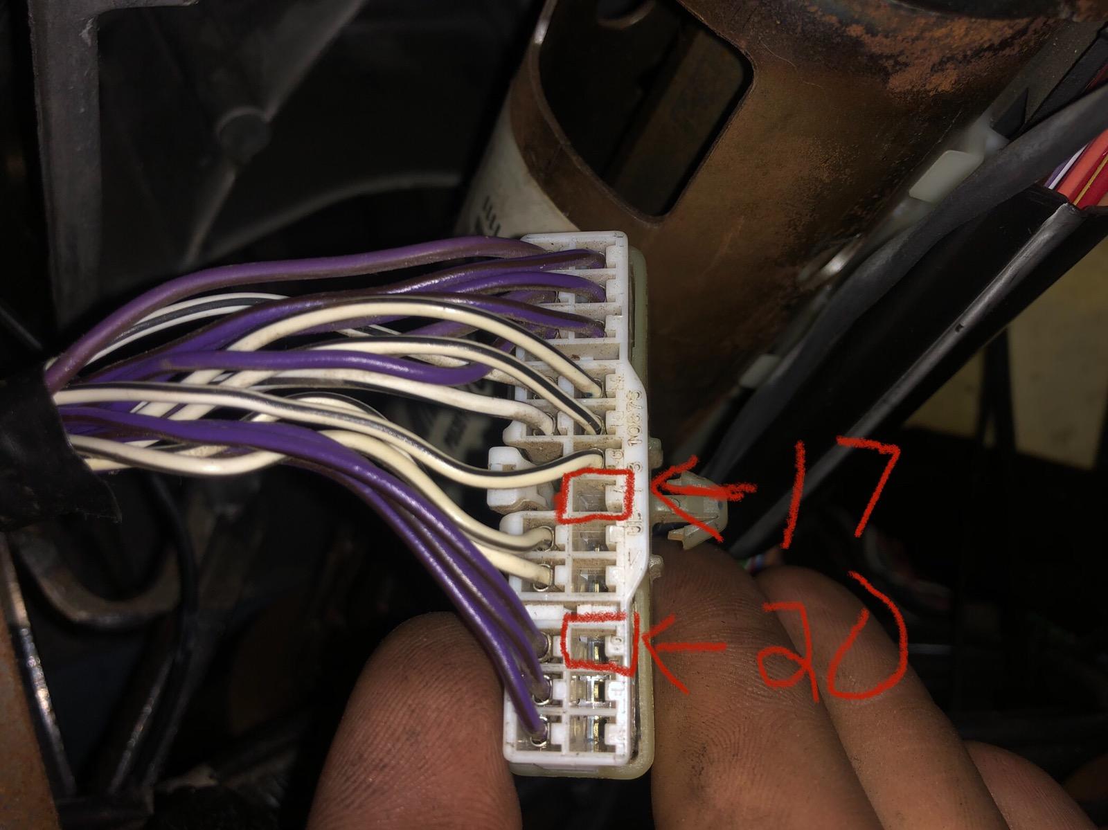
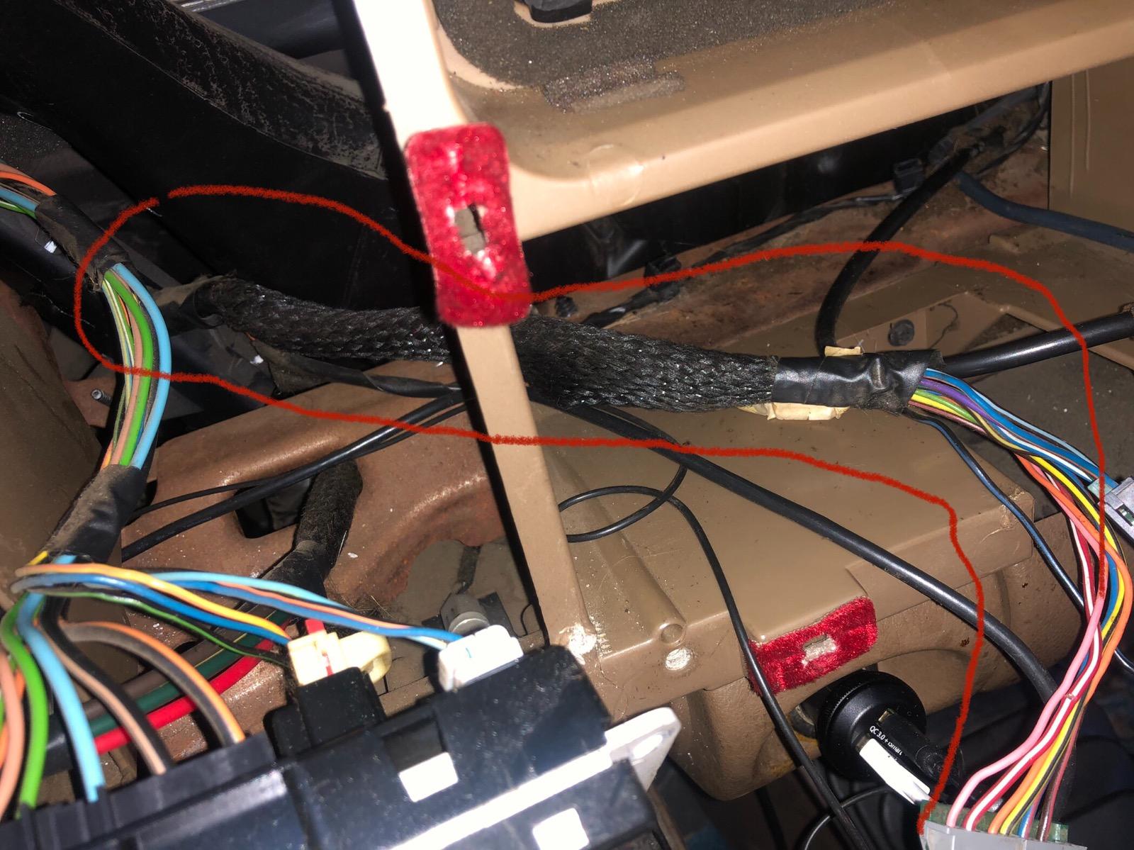
Check and clean C3 connector on PCM and the two connectors near center of firewall by vacuum tee. Also two splices above AC accumulator in the harness. Have a helper watch dash while flexing and wiggling connectors and wiring.

I did pull and separate the 2 connectors by the vacuum tee, didn’t see anything abnormal on them and so put them back together. I’m going to be moving to testing the PCM connector today, thanks for the splice info I’ll be sure to check those out also. I’ll put together another list of things soon.


im just trying to document all these things because it seems like a common issue that has pretty limited detail info on it out on the web. So hopefully I can fix my issue and help someone else down the line one day.

Link to comment
Share on other sites

Ok now to PCM connector


tach dead, issue present. Pulled all 3 PCM Connectors, visibly they have no signs of damage, all pins look to be fully seat to the connector. All this is with Key Off, Battery Connected.


6th Test - PCM C3 Pin 28 to OBD Pin 3 - 119.7 ohms, didn’t fluctuate at all


PCM C3 Pin 28 to OBD Pin 11 - 0.8 ohms


PCM C3 Pin 30 to OBD Pin 3 - 0.5 to 0.6 ohms


PCM C3 Pin 30 to OBD Pin 11 - 119.9 random spikes down to 102 ohm


7th Test - PCM C1 Pin 31 to Ground - 0.2 ohm


I also started pulling the harness wrap apart starting at PCM, only found the violet wires splice and that was over the valve cover, the white wire splice must be closer to the 2 connectors by the vacuum line. Still going over stuff at the moment.


After doing all this and then reconnecting the dash came back to life, gonna let it idle and see if it reoccurs or maybe the area I was testing is the issue. (I’m doubtful tho) update: dead again


So now that it’s dead again I recheck Pin 3 and Pin 11 at OVD I have 2.48V and 2.42V is this off by enough to be an issue?


Based on all this info does anyone have any ideas? I feel like these readings seem to be okay not sure what my next step would be, I mean the one CCD like has a smidge extra resistance but it doesn’t jump around. I’m sort of worried about the clusters 120ohm resistor that when I test the one direction randomly drops to 102ohms. Not sure if it’s time to send my ecm and pcm out to be tested

Edited by teknic
Link to comment
Share on other sites

Disconnect all optional modules one of them may be corrupting the bus and leave them off. If problem persists  then stress ECM with freeze spray or ice. Then heat with hot air.  Repeat. Watch display as heated or cooled. This can help rule out or rule in ECM. Intermittent problems need more than continuity checks and without known good parts to swap stressing is the only option.

Link to comment
Share on other sites

8 minutes ago, Great work! said:

Disconnect all optional modules one of them may be corrupting the bus and leave them off. If problem persists  then stress ECM with freeze spray or ice. Then heat with hot air.  Repeat. Watch display as heated or cooled. This can help rule out or rule in ECM. Intermittent problems need more than continuity checks and without known good parts to swap stressing is the only option.

So disconnect everything on CCD besides cluster/ECM/PCM and just monitor to see if gauge issue occurs while heating/cooling/shocking ecm?

Link to comment
Share on other sites

×
×
  • Create New...