Skip to content
View in the app

A better way to browse. Learn more.

Mopar1973Man.Com

A full-screen app on your home screen with push notifications, badges and more.

To install this app on iOS and iPadOS
  1. Tap the Share icon in Safari
  2. Scroll the menu and tap Add to Home Screen.
  3. Tap Add in the top-right corner.
To install this app on Android
  1. Tap the 3-dot menu (⋮) in the top-right corner of the browser.
  2. Tap Add to Home screen or Install app.
  3. Confirm by tapping Install.

Another NO BUS truck. It's challenging me... LOL

Hello, I have a 2002 Dodge 2500, 5.9L 24V Cummins that’s been down for months & so far is stumping me. It has Auto trans, 4WD, & about 190k miles. As far as I know it’s all stock except for a FASS DDRP fuel pump. This is a long one, but any help or suggestions would be greatly appreciated!

Truck was running fine & then died. Cranks (spins good), but no start. First thing noticed was fuel pump not running. Then also saw gauges are not working, no wait to start light, & odometer flashes a few times then displays “NO BUS”. It will connect but not communicate with a scan tool. It either displays no communication from module or circuit open (from the airbag module). The OBDII scanner adapter lights up & I have Ign + & ground at the connector.

That of course lead me on a CCD communication path for troubleshooting. I started by disconnecting each module or component, 1 at a time, in the CCD circuit. Got it down to only ECM, PCM, & cluster connected- no change. Went ahead & removed the cluster & still no start. While removing I inspected each connector for damaged terminals, corrosion, or dirt. They all looked good.

I then checked the CCD wiring- for short to each other (the Bus + & Bus - pairs), short to ground on each wire, & short to Ign + on each. No shorts or incorrect continuity found on any of that. I also continuity tested each CCD terminal to all the other connector terminals for each wire. Every terminal has continuity with all others on each of the wire pairs.

I then started checking all the grounds, battery +, & Ign + wires to the ECM, PCM & OBD II connectors, Every one of those tested well (even load testing them). I have also checked all fuses (good).

At some point in there I self-tested the cluster. Every light & gauges seems to function properly. At the end I get 920, 921, & 999 errors in the odometer display. Seems to point to PCM problem…

I have checked battery grounds to body & other points. All OK. I haven’t dug into doing a W-T ground wire mod, but doesn’t SEEM to be an issue with that either. Maybe I’m wrong though?…

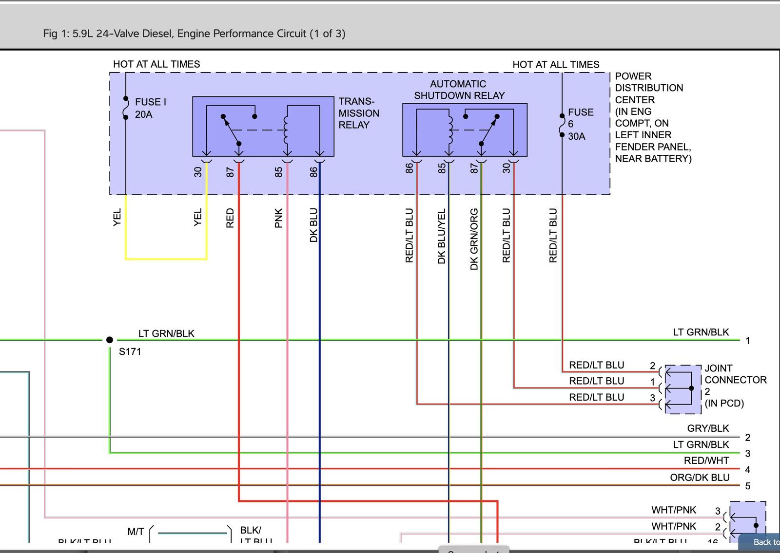
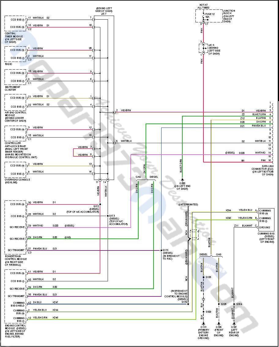
There is a ground wire to the block just above the starter & according to wiring diagrams, it grounds the fuel pump, fuel heater, A/C compressor clutch, & the CAN-BUS ground. The wire terminal seems good & 3 of the 4 connectors have good continuity to ground. I haven’t found the Cummins Can-Bus connector to check that. Diagrams show it’s located on front left of engine & has 3 terminals ( Bus +, Bus -, & ground). I’m unsure of where or how to check that….

I pulled the PCM & sent it off for bench test & repair. It was returned saying nothing wrong with it. Next I sent out the ECM. They found some corroded terminals & repaired solder connections. I was hopeful that their findings were the issue, but no change after reinstalling so doesn’t seem to be either of those.

Next I went digging deeper in the CCD system. I’ve gone through some flow charts that don’t seem to show any issues. I’ve read multiple threads on here about CCD & saw posted that you need 2.49- 2.51v on each of the CCD wires to ground. I have 2.45v on each of them. I have a troubleshooting flowchart from Mitchell ProDemand that says I need 1.8v to 2.3v. So I guess I’m in range, but can’t say 100% either.

Swapped PCM with a good running 2001 Cummins 2500, AT, 4WD. Both trucks functioned the same way as before even with a different PCM. This truck still had flashing odometer & NO BUS with the ’01 PCM. The other truck ran fine on the ’02 PCM. So that tells me the PCM in this truck is probably fine.

The only thing that I can think of is to either swap the cluster (but I don’t really think that will do anything) or go back through all my wiring & fuses again in case I missed something. Or I am very open to suggestions if you have thoughts on this? Thanks for any help. I greatly appreciate it.

Edited by 4x4 Nut

  • Replies 10
  • Views 548
  • Created
  • Last Reply

Top Posters In This Topic

Most Popular Posts

  • Tractorman
    Tractorman

    I won't be able to offer any help - I am responding because you haven't received a response yet and I didn't want you to think you were being ignored. From reading your post it seems that you have

  • Mopar1973Man
    Mopar1973Man

    CANBus was left for the "Cummins Insite" tool for the diagnostic connector. 2003 The CANBus was introduced to the 3rd Gens. We are just in the testing stage of this with the VP44 communications.

  • 4x4 Nut
    4x4 Nut

    The PCM connector & pins are nice & clean. I have good continuity between pin 85 at the ASD & pin 3 on C3 of the PCM. And also good continuity between ASD pin 87 & PCM pin 12 on C3.

Posted Images

Featured Replies

I won't be able to offer any help - I am responding because you haven't received a response yet and I didn't want you to think you were being ignored.

From reading your post it seems that you have been very thorough in trying to get your issue resolved. You have checked everything that I can think of that needs to be checked.

Maybe @Mopar1973Man will respond now that I have flagged him. He is knowledgeable in this area.

  • John

  • Owner

Sorry been on the road limited cell service.

My suggestion at this point I would consider contacting Auto Computer Specialist and have the PCM and ECM tested. Something is wrong if the wait to start does light up, fuel pump not bumping at key on. Then the PCM creates the CCD bus so. Wiring on the CCD would need to be checked for sure. Bias voltage is not correct even after removing modules.

  • Author
12 hours ago, Mopar1973Man said:

Sorry been on the road limited cell service.

My suggestion at this point I would consider contacting Auto Computer Specialist and have the PCM and ECM tested. Something is wrong if the wait to start does light up, fuel pump not bumping at key on. Then the PCM creates the CCD bus so. Wiring on the CCD would need to be checked for sure. Bias voltage is not correct even after removing modules.

No worries. Thanks for replying! Do you know where the "Cummins Bus" component is located? It's listed in the wiring diagrams with 3 wires to it. It's the only item I haven't been able to get my hands on so far. It's located in the bottom & towards the right in the diagram below. Says front left of engine, but I don't see anything.

I was quite prepared to have the PCM looked at again, but then earlier this week I swapped that with one from the good running '01 & it made no change- This '02 truck didn't work any better with the '01 PCM & the '02 truck ran fine on the '01 PCM. So I'm thinking the PCM has to be working OK. Maybe it's time I recheck continuity on the CCD pair & all the ground & + wires to ECM & PCM.... 🤷‍♂️

2002-Dodge-Wiring-Pg2.jpg

  • Owner

17758396011945180509893287588004.jpg

CANBus is right near the ECM typically used for tuner connection. Wire map above covers both the CANBus and CCD bus. CANBus is used for the VP44 injection pump and tuner data.

Edited by Mopar1973Man

  • Author

Thanks. So is that just a wire connector that's not plugged into anything then? Allowing a tuner to connect directly to the ECM vs the OBDII port?

  • Owner
On 4/10/2026 at 1:08 PM, 4x4 Nut said:

Thanks. So is that just a wire connector that's not plugged into anything then? Allowing a tuner to connect directly to the ECM vs the OBDII port?

CANBus was left for the "Cummins Insite" tool for the diagnostic connector. 2003 The CANBus was introduced to the 3rd Gens. We are just in the testing stage of this with the VP44 communications.

Edited by Mopar1973Man

  • 1 month later...
  • Author

Update! Hello all, I finally made significant progress on the '02 Cummins with NO BUS message & crank/ no start. I've found that the Auto Shut Down relay is not being activated. I jumped the power to load terminal where the relay fits into the Power Distribution Center & things in the dash began to function correctly- all the gauges were working, the wait to start light worked, & no more NO BUS message is displayed in the odometer. The fuel pump is also working as normal. I had to bleed the injector lines & crank on it a bit, but it now runs again.

I still have to find why the ASD relay isn't being powered & repair, but I at least know WHERE the problem is coming from. Thanks for your help guys!

  • Author

Another update & today's puzzler.

I had the truck running with a jumper wire at the ASD terminals (between the battery & load terminals) which I was very happy to hear it run & find the area the problem is from. While going through different things with it I had the relay back in at one point & it functioned properly (dash lights good & no error). So I wondered about a faulty connection and/ or wire. I lifted the Power Distribution Center (PDC) & removed the lower cover to see if any corrosion or faulty wires underneath. Also looked at the big square harness connector that connects to the PDC. Everything looks good. I put the PDC back in place along with the harness connector. Then I tested continuity between the 2 ASD relay terminals that connect to the PCM- 1 is the trigger for the relay & the other sends power to PCM. Both circuits were good. So I put it all back together & checked the relay itself. It functions OK & has continuity between the switched terminals. So with that everything SEEMED OK. I used a pick & tightened the ASD terminal openings in the PDC just in case there was a bad connection to the relay. I checked another relay also (also worked fine) & just swapped it with the ASD spot. Put everything back together, hopeful that it was working, & unfortunately the same problem- gauges aren't working & NO BUS error in odometer. So, I jumpered the ASD terminals again & this time the cluster works fine, but it won't fire.

I then retested the ASD terminals. Both the battery slots have voltage. I don't get a ground on control wire from the PCM though like I should. Until I jumper the battery & load wires. Then I get a ground signal from the PCM. That doesn't make sense because I'd think the PCM has to first signal the relay to work before the relay can send power, but it's not triggering the ASD until it's jumpered.

Any thoughts are welcome. Thanks

Edited by 4x4 Nut

  • Owner

Engine System (Page 1) wiring map 1999 Dodge Ram

Double-check the PCM socket for any damage or corrosion. Which should be pin 85 of the relay. The PCM controls the ground to Pin 85. Then pin 86 gets ignition power to energize the relay. If you do not have a ground signal, then the PCM would need to be sent in to be rebuilt. I would send it off to Auto Computer Specialists in Florida. Here shortly, I'll be sending Thor's ECM to get the exhaust brake circuit fixed.

  • Author

The PCM connector & pins are nice & clean. I have good continuity between pin 85 at the ASD & pin 3 on C3 of the PCM. And also good continuity between ASD pin 87 & PCM pin 12 on C3.

Mine is a little different than the diagram you have posted. On mine, the ASD pin 86 gets battery constant power just the same as pin 30. Both get power through the PDC joint connector #2, which is just a terminal jumper in the PDC.

I'd also suspect a PCM fault, but I had sent that out for testing & repairs a few months ago. It was returned with no problems found. Not saying they couldn't have made a mistake or something happened since then, but I'm hesitant to think the PCM is faulty....

Here's a diagram of what I have. Thanks!

https://www.srsplatform.com/webservices/Srs.WebPlatform.WebServices.FileManager.svc/POX/Get?sessionTokenId=54e26f0b-55fb-4d2e-a2b5-28f178085e58&project=OemContent&file=Wiring\Display\wrcr02\ram25074a.png

Account

Navigation

Search

Search

Configure browser push notifications

Chrome (Android)
  1. Tap the lock icon next to the address bar.
  2. Tap Permissions → Notifications.
  3. Adjust your preference.
Chrome (Desktop)
  1. Click the padlock icon in the address bar.
  2. Select Site settings.
  3. Find Notifications and adjust your preference.