
Cowboy
Unpaid Member
-
Joined
-
Last visited
Everything posted by Cowboy
-
That is something I have yet to do, caster and tire pressure. I believe the wheels were off a gasser, so who know what kind of pressure he set them too.
-
Arduino Due 4.3" TFT display with shield Pressure Sensors EGT Thermocouple PCB designed with Diptrace Electrical components; 1 x MAX31855 1 x CD4051 1 x DS1307 1 x LM393 1 x TC26H 32.768kHz Crystal 1 x 2032 Battery Holder 2 x 8 pin DIP socket 1 x 16 pin DIP socket 10 x 2 pin angle connector 3 x 3 pin angle connector 1 x 8 pin angle connector 1 x 4 pin 3.96mm angle connector 5 x 8 pin header 1 x 10 pin header 1 x 2x3 pin header 1 x 18x2 pin header 2 x 100n ceramic capacitor 5 x 1N4148 diode 2 x 270r 1/4 watt resistor 1 x 1k 1/4 watt resistor 3 x 1k1 1/4 watt resistor 3 x 3k9 1/4 watt resistor 5 x 10k 1/4 watt resistor 2 x 100k 1/4 watt resistor 3 x 1M 1/4 watt resistor 2 x 3mm LED Power Supply 1 x LM2596T-ADJ 1 x AIUR - 08 Inductor 1 x LM317BT 1 x LM7805 1 x 1N5822 4 x 1N4007 1 x 2 pin connector 2 x 100u Capacitor 2 x 470u Capacitor 1 x 1k 1/4 watt resistor 1 x 5k5 1/4 watt resistor 1 x 2.1mm DC plug 1 x 4 pin 3.96mm Connector 1 x 12 volt relay 1 x heat sink Main board Power Supply Schematics: Pressure Sensor interface: http://s20.postimg.org/pwkz4h6ct/screenshot_145.png RTC: http://s20.postimg.org/4o7an1rvx/screenshot_146.png Variable Reluctance Sensor interface: http://s20.postimg.org/dyjeql2lp/screenshot_148.png Thermocouple Interface: http://s20.postimg.org/vedksa1kd/screenshot_150.png LED's: http://s20.postimg.org/tvi6nauzx/screenshot_147.png Power Supply: http://s20.postimg.org/59w9j5my5/screenshot_152.png Total cost, $300-400. I don't mean to make you pull all the info out of me, but this isn't a simple "plug and play" deal, you pretty much have to design it for yourself.
-
More info?! I don't know what else to tell you. I don't have any experience with the CAN BUS, but if go on google or youtube, you'll see where lots of people have done it. I would do it on mine, but there isn't that much data to be read from the CAN BUS. RPM, MPH, Water Temp, and that's about it for the 12 valves IIRC. The code compiles to 111kb... I'm not even going to start try to explain it further then that, unless someone cares. I'm using the arduino Due and designed my own shield for it, there are however a couple things I am going to change on it for the next go around. But as is I'm using a MAX31855 thermocouple to SPI chip, and then a CD4051 multiplexer to give me 8 temp inputs. The pressure reading is simple, though I've got a bit of over/under voltage protection added, and a resistor divider to work with the 3v3 logic. RPM/MPH will be read through a LM393 to give me some protection. I've got a plug-in for an SD card, though I am currently using the SD card holder on the back of the LCD. I have a DS1307 RTC on board as well, but I am not currently using it.
-
It's homemade, I've had a bunch of help from a friend who is much more fluent in this stuff then me. The data gets saved on a SD card in a .csv format. Here's the latest, not many changes sense this video. Now that the software is just about done, I'll try and get a video of everything.
-
If you want to make sure they are at TDC, then just watch for valve overlap and do its mate. So if #6 is on valve overlap, you know #1 is just about exact TDC, and plenty close enough for dropping the valves. Just take your time and it will be easy. Worst case, you drop a valve in and have to pull the head.
-
I'm pretty excited! I've been working on this project off an on for about a year, and finally took it for a test drive today! There are a couple bugs that showed themselves, but it worked well enough to get a little data from. These are all at 1/2 second update rate, forgot to change it back to a little faster rate before taking off. RPM also seems to give weird readings at times, not sure if that's a software or hardware issue. This one is starting in 2nd going up a small hill. Totalling about 1:45 minutes. I "benched" my wastegate and have it so it just starts to open at 20 psi, so it seems to be working as it should. I have to adjust the rod for a little higher pressure. The first half of this one is road, the second is pulling in the driveway, and parking haha. totalling about 5 minutes. (this is me testing some things, not exactly my normal driving habits lol.) Hopefully I can get a couple more sensors working for next time. But over all, I think it went well for the maiden voyage!
-
I'd suggest to bring each set of pistons to top dead center, way to easy to drop a valve using the air pressure trick. because there are running mates, you can do them in sets, ie, 1&6, 2&5 and 3&4.
-
5/16" should do the trick. I have hose double-clamped over the male part of the quick-connect and have had no issues, even at 45 psi.
-
It is a VR sensor, you'll need to hook it up to digital pin 2 or 3, and then count the pulses with an interrupt.
-
SensorValues[8][0] is just an 2D array, I use it in my code to make processing the values easier. You can replace it with TurboRPM = ((60000000UL * RPMPulses)/(RPMTimeLast - RPMTimeStart)); and then put this globally. long TurboRPM = 0;
-
I would not let programming discourage you. A)Arduino has made it very easy for beginners. And once you get just a couple of the basics down, you will be able to achieve what you're wanting easily. C)There a multiple people on this forum alone that would be happy to help. Heck, if you tell me what you want it to do, I'll write the code for you.
-
Interesting turbo, a friend has a S300V that he wants to put on his 24 valve. Though that project has been put on hold for a couple months now. He did make mention that when controlling it with PWM, the frequency has to be 100-140 hz. So it's not as simple as a "analogWrite(Value);". But will still be fairly simple with a little bit of extra code. If you decide not to use it, I may be interested.
-
Ed, that would work. Though negative values won't read correctly. So you might consider either limiting the lower value of the analog input; to chop off anything under 0 psi. Or map it to a wider range to include the negative values. So either: int ReadExhaustPressure(){ int ExhaustVal = analogRead( ExhaustPressurePin ); // read the value from the sensor if (ExhaustVal < 103) ExhaustVal = 103; return map( ExhaustVal, 103, 920, 0, 100 ); Or: int ReadExhaustPressure(){ int ExhaustVal = analogRead( ExhaustPressurePin ); // read the value from the sensor return map( ExhaustVal, 5, 920, -12, 100 );
-
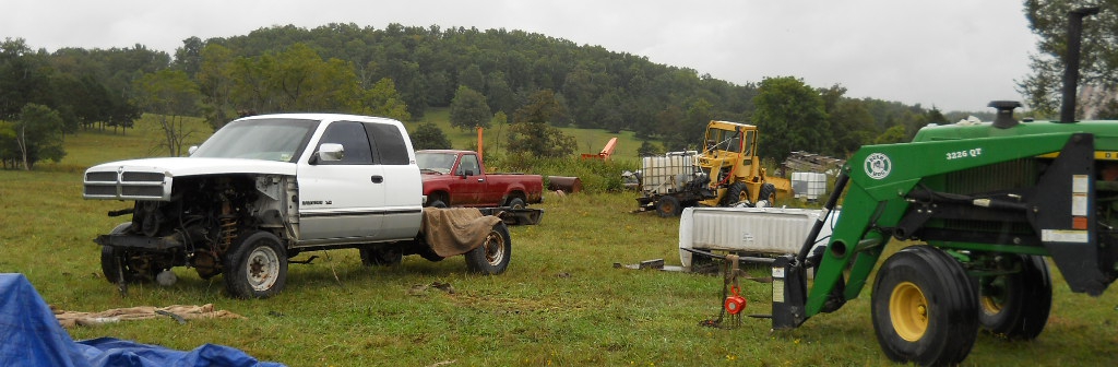
Haha, that's a Redneck truck driver alright! Probably just waiting for someone to throw some beers in the back, and then take off! Here's one I snapped a couple years ago, still no clue how they got up there...
-
I was going to post up the circuitry for the turbo sensor, but if you insist lol. (HERE it is anyway haha). I normally put him in globally... otherwise he's all over the place. Cape could be a good addition.
-
Oh lol. Just change the above 30000000UL to 60000000UL, and that should give you Turbo RPM.
-
I've been trying to figure out the speed sensor as well. from the math I've done, the VR sensor for the ABS in the rear fires at 1432 hz @ 60 MPH, which is a little more than I was hoping for. I was going to look into the VSS in the T-Case cause mines a 12 valve. Here's my RPM sensing code, you'd have to tweak it some for the Uno and MPH. void RPMSetup(){ pinMode(EngineRPMPin,INPUT); attachInterrupt(EngineRPMPin, RPMInterrupt, RISING); } void RPMInterrupt(){ RPMTimeLast = micros(); ++RPMPulses; } int ReadRPM(){ if (RPMPulses >= 2 && (RPMTimeLast - RPMTimeStart) >= 100000){ noInterrupts(); SensorValues[8][0] = ((30000000UL * RPMPulses)/(RPMTimeLast - RPMTimeStart)); RPMPulses = 0; RPMTimeStart = RPMTimeLast; interrupts(); RPMUpdateLast = millis(); } else if ((millis() - RPMUpdateLast) > 1000) { SensorValues[8][0] = 0; } } Also, I find this comes in handy for testing code speed. long Start = 0; //Global void StartTime(){ Start = micros(); } void PrintTime(){ Serial.print('-'); Serial.print(micros()-Start); } void PrintlnTime(){ Serial.print ('-'); Serial.println(micros()- Start); } And then one last thing. I meant to give you this earlier to help with my buggy code. /* WARNING: The code that follows will make you cry; a safety pig is provided below for your benefit _ _._ _..._ .-', _.._(`)) '-. ` ' /-._.-' ',/ ) \ '. / _ _ | \ | a a / | \ .-. ; '-('' ).-' ,' ; '-; | .' \ \ / | 7 .__ _.-\ \ | | | ``/ /` / /,_| | /,_/ / /,_/ '`-' */
-
Here's my pressure reading function in a different project, encase it's of help. int PressureRead(int AnalogPin){ int AverageNum = 3; int Val = 0; for (int i = 0; i < AverageNum; i++){ Val += analogRead(AnalogPin); } Val = constrain((Val/AverageNum), 103, 920); return map(Val, 103, 920, 0, 1000 ); }
-
The "jumping around" can be cause by the DP taking charge putting the veins position down getting it down. and then the boost map taking control again and kicking it back up. you could make a "free zone" drive pressure range where the map can't close the veins. and the drive pressure manage function can't open them any. I think having a backup drive pressure manage function is a good idea. But that's just my opinion.If the Torque at the wheels is the exact same, but the HP at the wheels is double. Then the wheels are spinning twice as fast. Which case you may be right, but that seems like more of an argument of aerodynamics rotational mass, and momentum. Not so much HP vs Torque. The 400hp one would be spinning twice as fast. Which would mean your speed would be double. Which would mean they would accelerate together until the 200hp motor runs out of revs. I don't have a perfect test for you, though there was this one route I'd take with about a 45k load. To get up this one hill, you have to hit it in 3rd, and then there was a short flat spot where you would then down shift to 2nd and get the RPM's to about 2500-2700 and floor it. The RPMs would then drop until they got around 1800 where it would stay for the last half of the climb. This is with a 01 nv5600 and 3.54's. That is a excellent example. The Torque at the wheels required didn't change. And neither did the speed. and thus the HP required didn't change. Cause Like said, and transmission is a RPM to Torque converter. whether it be buck or boost. And so the HP going in is the same as the HP going out. But the torque is what changes. And with the transmission you can take advantage of the HP by putting it in a lower gear. I want to thank everyone in this thread. When I was a kid, I asked my folks "what is the difference between HP and Torque?". Being home schooled they made an assignment out of it lol. This is the first time I've been able to discuss this publicly, cause it's one of those topics I wouldn't touch with a ten foot pole on a different forum. So thank you!AH64ID I'm not sure if understanding you correctly. Power is the amount of work something can get done. Torque is the rotational force of something. whether that be a torque wrench, an engine. Lots of torque does NOT mean lots of power. RPM is how fast something spins. Again, lots of RPM does NOT mean lots of power. We all know (Torque * RPM) / 5252 = Horsepower. Now, what is it that actually pushes the truck forward. It's the torque presented to the rear wheels. So lets say we have two engines. Both make 800 lb/ft of torque all the way through the RPM range. Though Engine #1 defuels @ 1700 RPM. And Engine #2 defuels @ 3400 RPM. If we do the math, Engine #1 makes 259 peek hp. And Engine #2 makes 518 peek HP. Now lets say you load them both with the same amount of weight to where they can barely maintain speed @ 1600 RPM. We know that they are both are putting down 3280 lb/ft of torque to the wheels (perfect world with no friction loss). Now, you try and take a hill. They will both slow down at the same rate. WHAT!?!? Well, lets try backing up engine #2 and try taking the hill again but this time at @ 3200 RPM... You're still going to decelerate at the same rate. And the answer is simple, the torque to the wheels is still the same 3280 lb/ft as before. So all Engine #2's HP is for nothing? I mean where did all it's extra power go?!?!?. Again simple. Your engine is turning twice the speed, and so your wheels are also. And because power is torque*speed, you are making double the power as the first run. Now there is one more thing that we need to remember. These Engines are also fitted with a transmission, and what a transmission really is, is an "RPM to Torque" converter. And So it enables us to take #2 Engines extra RPM capability, which would otherwise be useless to us as we're not trying to go any faster, we're just trying to make it up the hill. And Convert it to useable torque. With that knowledge, we can take engine #2 for another try up the hill. But this time, you'll shift the transmission to a 2:1 ratio. And again we'll be at 3200 RPM. So we're travelling at the same speed as the first try, but once we hit the hill, we'll have twice the available torque at the wheels. Which in the end, is what takes us up the hill.I'm using a 100 psi sensor for both boost and exhaust, I believe Nick is doing the same. I should pull the map sensor of the one 99 and see what I get, can't promise I'll ever get around to it though. lolTwo blonde girls were working for the city public works department. One would dig a hole and the other would follow behind her and fill the hole in. They worked up one side of the street, then down the other, then moved on to the next street, working furiously all day without rest, one girl digging a hole, the other girl filling it in again. An onlooker was amazed at their hard work, but couldn't understand what they were doing. So he asked the hole digger, 'I'm impressed by the effort you two are putting in to your work,but I don't get it -- why do you dig a hole, only to have your partner follow behind and fill it up again?' The hole digger wiped her brow and sighed, 'Well, I suppose it probably looks odd because we're normally a three-person team. But today the girl who plants the trees called in sick.' encase anyone is wondering why all the blonde jokes... I get the opportunity to hear a lot of them, cause I guess I'm technically a blonde...The first 2 minutes of the second video I posted shows me changing the EB Pressure from 60 to 65. Though I misunderstood what "MaxExhaustPressure" was and thought that was the desired EB pressure. So now that you added the "ExPrsBuffer" to the EBManage code. The numbers in the menu won't be correct. So you can either make a global "DesiredEBPressure" variable. Or change this; case 0://what page are we on. MaxExhaustPressure = ChangeValue(MaxExhaustPressure, PotValue, 1, 0, 80); To this; case 0://what page are we on. MaxExhaustPressure = (ChangeValue((MaxExhaustPressure - ExPrsBuffer), PotValue, 1, 0, 80) + ExPrsBuffer); Also, you probably already noticed this, but I should let you know. The Menu system is inside a while() loop. So when you're in the menu, it is not controlling the turbo at all. So it would be best to use the menu only when the truck is off just encase something stupid happens. Changing this; if (SwitchPosition && ThrottlePosition <= 15) {//if the PotSwitch is off, and throttlePos is below 1.5% To this would likely be a good safety feature as well; if (SwitchPosition && ThrottlePosition <= 15 && ExhaustPressure <= 1); {//if the PotSwitch is off, and throttlePos is below 1.5% I have yet to hook up a drive pressure gauge. Though boost gauges says .2 psi at idle, so I have to imagine that drive pressure is going to be above 1 psi.