

.jpeg.498813ce7eb5d3c936d5d5a798256129.jpeg)
xxTJRocksxx
Unpaid Member
-
Joined
-
Last visited
Everything posted by xxTJRocksxx
-
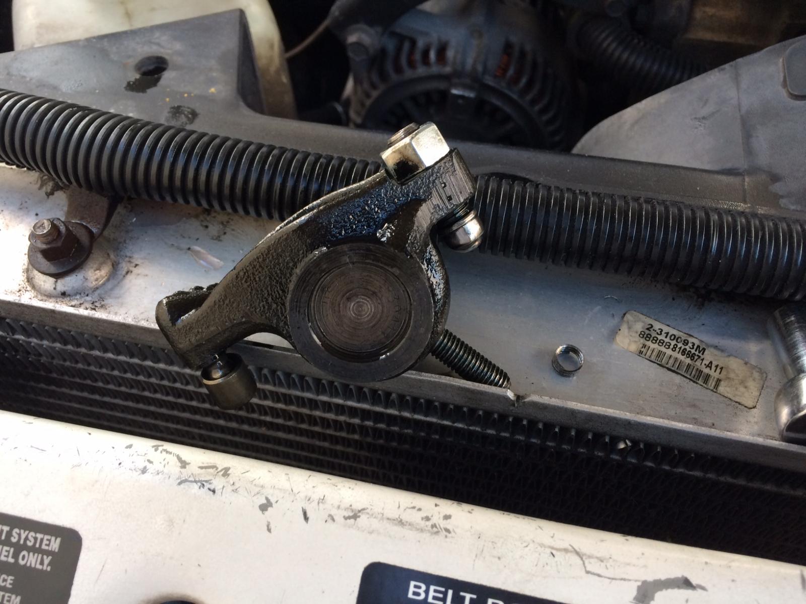
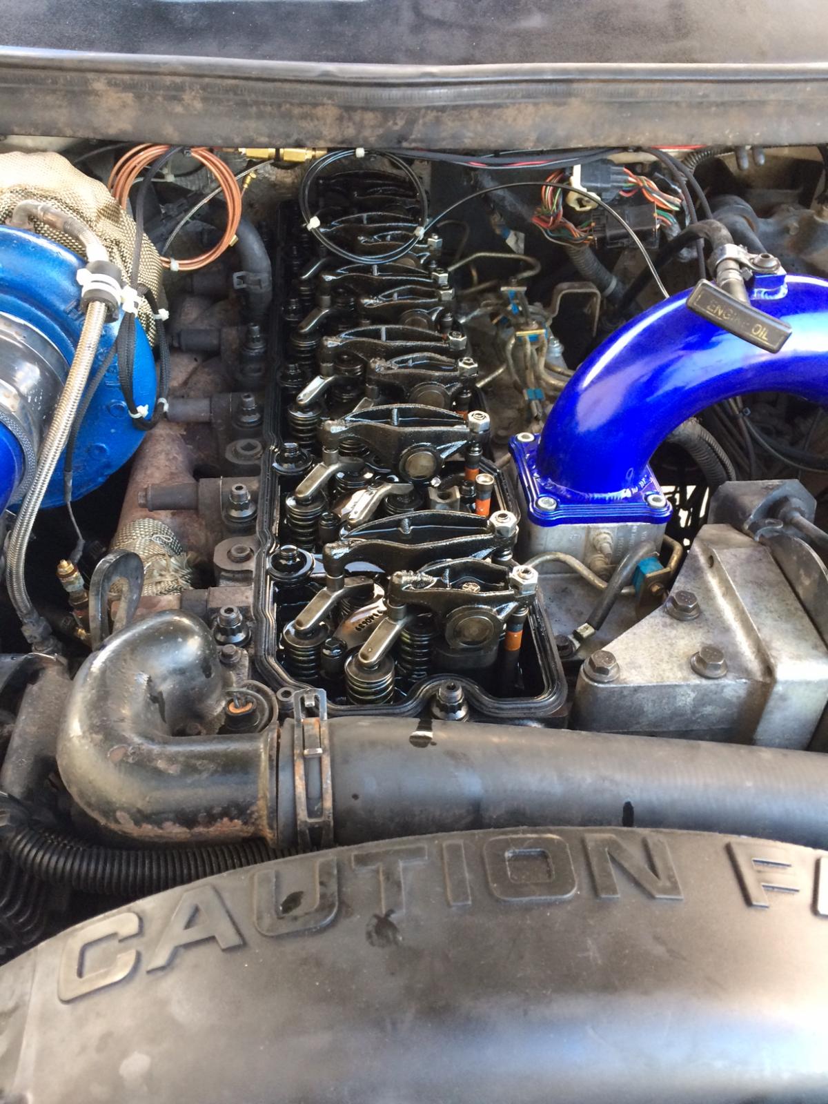
Head gasket is def blown, but the quad says I only hit max 37 psi of boost. I read on other forums where people had intake and exhaust rockers break. Unless I over torqued the rocker bolt IDK why it would fail 200 miles later
-
Apparently this is a common issue on 24V Cummins.
-
Hey Guys, So I guess this is just poetic justice. I installed my ARP stud kit Wednesday Night, and logged about 200 miles since installation. I originally planned to re torque everything and re check valve lash sunday. Unfortunatley disaster struck this afternoon and I am defeated. Firstly, I haven't beat on the truck very much. I left the Boost defuel on the quad set to 45 PSI. I left a stop sign on my way home from work today, and according to the data log I hit 37PSI of boost. I came to a stop and had a #2 cylinder miss, and White steam from the exhaust. I limped the truck a half mile back to my office, and now I sit here waiting for my wife to pick me up. I guess I am going to get some seat time on my CBR 1000 this week lol. What I know so far: -Missing Antifreeze -No coolant in oil. -#2 Intake rocker came loose, Bolt pulled 4 threads from the head. - Push rod is not bent, and during cranking it moves up and down correctly. My suspicions: -Either I overtorqued or undertorqued the #2 Rocker, and it just decided to fail two days later. (Yes I checked the lash after installing the studs, I planned to re check it Sunday) -When the rocker failed, The added negative pressure on the intake stroke blew the head gasket. My Hopes: -Just need to re machine the head, and replace the gasket. Might as well do fire rings and valve springs while I am at it.
-
The Bypass in those PS pumps is just ball - spring type. I would wager your spring let go after the extended high RPMs + Steering demand in the ditch
-
A gun is no more than a "calibrated aperture" used to accelerate a self powered, self contained projectile at high velocity. People are the dangerous weapons
-
@TFaoro I completely agree with you on the studs, I have to re set the valve lash anyway (I just R&R'd the rockers) so I want to re torque and re lash this weekend on Sunday. I want to drive it around and put a few heat cycles to it before re torque. When I installed them I followed the following pattern religiously: 1 remove head bolt > Install stud > Hand Snug nut and washer, breaker bar 180*. do that 26X then Torque in 3 steps: 80 - 105 - 125 - 125 lbft. As for the Low boost scaling, I thought that only set the initial wiretap %, Does it affect the entire scale?
-
@Me78569 Sorry guys, the last couple weeks have been hectic. My Landlord decided to sell my house out of the blue so I had to get ready to make an offer to buy it and such. Videos are not great because its hard to record, shift, and drive at the same time lol. On a good note, I just finished my ARP studs, I did them in a 1 for 1 fashion. Man that was not as easy as I had presumed. Still have to go back tomorrow and re check valve lash after a few miles. Looking forward to 55 PSI Daily though. Also, I made a couple new tunes over the weekend if anyone is interested in the curves. Pretty much I am happy with my current Mileage tune XM2, but I don't really think much fuel is needed at cruise above 10 PSI. That being said I made a weird "S" Shaped tune that I am going to test next tank of fuel and see how it does. My truck really likes a load between 14-18%, and I get great mileage in this range, and O.K. mileage between 18% - 22%. As for V2, Like I have previously said my only complaints are with the I Quad App, and not the tuning. TimingVariables = Awesome. - I am not really seeing too much difference in performance with different timing sets, in a part throttle / daily commute. I do see some responsiveness and spool changes if I tweak too much, but the envelope is pretty big. I kind of found the two extremes of this and then settled on my 12* @ 80% standard. Seems like the 5.9 will go balls deep regardless of timing as long as its in the ball park. I'm sure more precise changes would be measured on the Dyno. Would be interesting if someone on here had access to a dyno and we could play with the timing and record the effects of more or less degrees + Scaling + Reduct +Reduct Scaling. obviously different mods would change data, but generalizations could be made. Fueling Variables = Canbus is great. Wiretap could use a couple features. Since the quad controls the wiretap fuel map, it would be nice but not extremely useful to have the ability to modify the wiretap scaling. I know we have TPS variable control for it , but Aside from min and max the quad determines how much and when. The only benefit to scaling the wiretap would be to modify the curve to get more wire tap faster, or less slower. Just wondering if that could be helpful for the guys running 80+ mm turbos that need tons of fire to get them to light off.
-
Oh you have a big turbo then but 2.5 is what I expected ~1500 RPMs. I wanted to overlay yours to mine to see what the ECU is doing with timing during all of this. you have injectors double the size of mine, and I wanted someone with stockers to do the same. I have been studying the timing reduction curve and now that I have a good timing curve for my setup 12*@80%, I wanted to see how the ECU fuels and times during low boost with different mods. It should be identical but I have a sneaking suspicion that its not even close.
-
So what is better IAT for power vs economy? Is 100* more optimal for power? is 143* better for MPG? My truck likes to run 105-137 IAT depending on ambient temp and whether I have AC on or not. Also, what is this live data tool you are using?
-
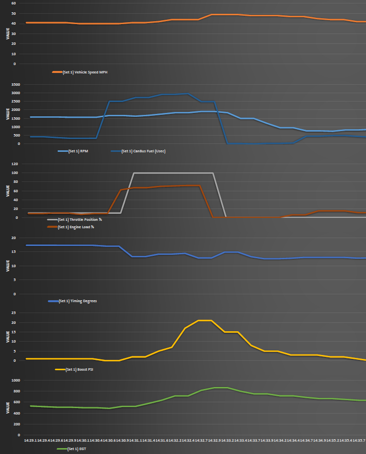
NEW INFO!!! Hey guys, I ran the following tests today All tests were done on the same tune, with timing scaling at 80%, and Timing Reduction varied from 3.5 to 4.5* Starting conditions were 80* ambient, coasting 40MPH in 4th Gear 1:1 ~1500RPMs Test performed: Time from 0PSI to 20 PSI boost. clock starts at 100%TPS. Test 1 - Max timing 12* / Reduct 3.5* - 0-20PSI = 1.91 Seconds Test 8 - Max timing 12* / Reduct 4.5* - 0-20PSI = 1.93 Seconds Test 2 - Max timing 10* / Reduct 3.5* - 0-20PSI = 2.00 Seconds Test 7 - Max timing 10* / Reduct 4.5* - 0-20PSI = 2.05 Seconds Test 3 - Max timing 8* / Reduct 3.5* - 0-20PSI = 2.04 Seconds. Test 6 - Max timing 8* / Reduct 4.5* - 0-20PSI = 2.03 Seconds. Test 4 - Max timing 6* / Reduct 3.5* - 0-20PSI = 2.12 Seconds. Test 5 - Max timing 6* / Reduct 4.5* - 0-20PSI = 2.07 Seconds. Bonus - PL=0 (Stock) 0-20PSI = 1.92 Seconds >>>>>> Data log recorded 1.80 Second Actual Please see below Data log and picure from PL=0 Timing Tests.xlsx @TFaoro Could you data log a 40 MPH roll on PL=0 for me? Looking for 100% TPS on flat ground, and 0% TPS after reaching 20 PSI of boost. You need to indicate 0-1 PSI before 100% TPS. If anyone has stock injectors, could you please do the same and send the log to me?
-
Good point on the pump TPS, I haven't been running above PL3, so no issues yet, but I will set everything back to 100% when I go to the track on the 16th. if you would like me to test any specific timing curves let me know. I will be doing data logs from each run on the track, I am setting up a throttle limiter which I will use to test stock fueling @ 20%, 40%, 50%, 60%, 80%, and 100% max TPS to start. From there I will adjust my tunes and try to get my aggressive tunes dialed in. then I can use that data to dial in the Daily / Screw around Tunes. I like the way you think sir, I will try this at the track on Test Tune 1
-
Hey Guys, I did a quick experiment the other night regarding max timing. Here is my results All tests were done on the same tune, with timing scaling at 53%. Starting conditions were 80* ambient, coasting 40MPH in 4th Gear 1:1 ~1500RPMs Test performed: Time from 0PSI to 20 PSI boost. clock starts at 100%TPS. Test 1 Max timing 15* - 0-20PSI = 2.16 Seconds Test 2 Max timing 10* - 0-20PSI = 2.09 Seconds Test 3 Max timing 8* - 0-20PSI = 2.07 Seconds Test 4 Max timing 6* - 0-20PSI = 2.09 Seconds. I did this test with an IPhone, so there could be up to 0.09 seconds error from reaction time.
-
Errrr roger that, Videos to come on the way to work tomorrow. So My tablet is android and I am an Avid google drive user. My tablet automatically uploads my data logs to my server when I pull into the Driveway lol.
-
@Me78569 can you try out my XM2 tune at your starting percent? I am interested to know what mileage you get. Attached is the .xls version if you want to try it. I just make a formula to add X amount of fuel to each scale so its easy to use on differently modded trucks. I am seeing 31 MPG on the overhead @ 70MPH. Also what do you think of 12* @ 80% Scaling? Quad Tune Calculator.xlsx
-
Hey Guys, I have been experimenting with so many tunes that I started a library and gave them their own "Codes" so I can keep track. Please see the Pictures Below, I am having good luck with Test Tune 1 / XA2 and Test Tune 2 / XM2. Regarding Timing, I am finding that my truck seems to like 12* @ 80% Scaling. Tune XM2 / MPG 2 Has good power down low, but leans out just enough on the highway for 31MPG @ 70 MPH on the instant disp. This is not a power tune, its not fast and on PL3 I can barely make 30 PSI with my compounds. I have attached the Curve graph for you to see how aggressive they are. I am running S366/HX35 Compounds and 7X0.010 SAC Injectors, on XM2 I barley get a haze with the pedal on the floor.
.png.b126ea3439afc2fbfe11e1a0a4c381ea.png)

-
Sounds Like too much timing at those temps, probably an Edge issue.
-
The positap is not a bad way to install the quad, it saves Quadzilla from having to give instructions to install a stealth type cover. Last thing you want as a manufacturer is to have your customers damage their equipment installing your product, so that being said they kept it simple. The positap works pretty well too, it doesn't need to carry much current just the solenoid signal.
-
is fuel pressure on your raptor adjustable? I installed that XDP fitting in the output from the raptor, and the sensor screws into it. Make sure you don't starve the VP, it will not live long at all, and its a 1500$ mistake if you replace it yourself. They mean 1/2" lines from the Tank to the LP and VP
-
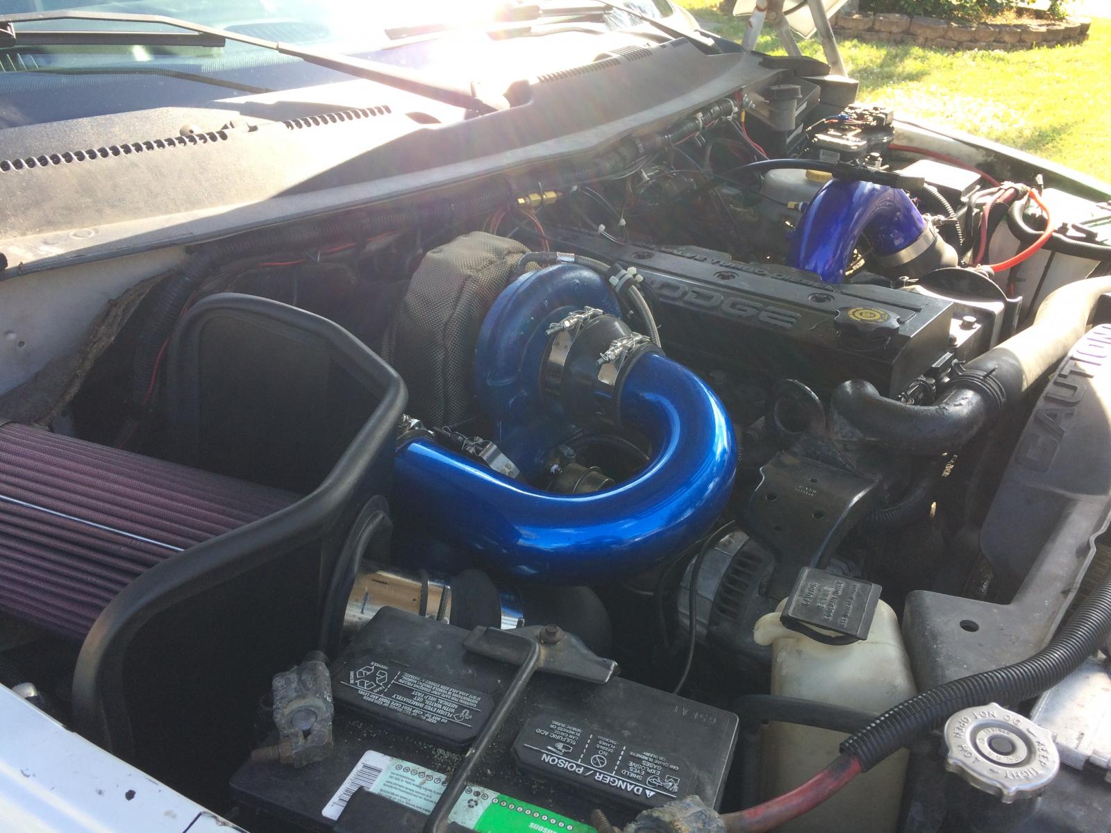
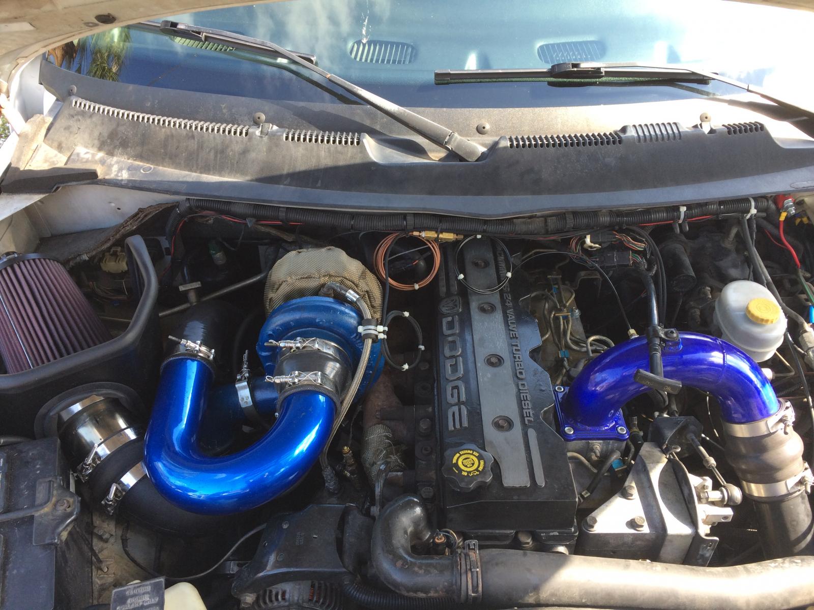
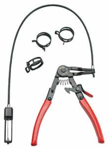
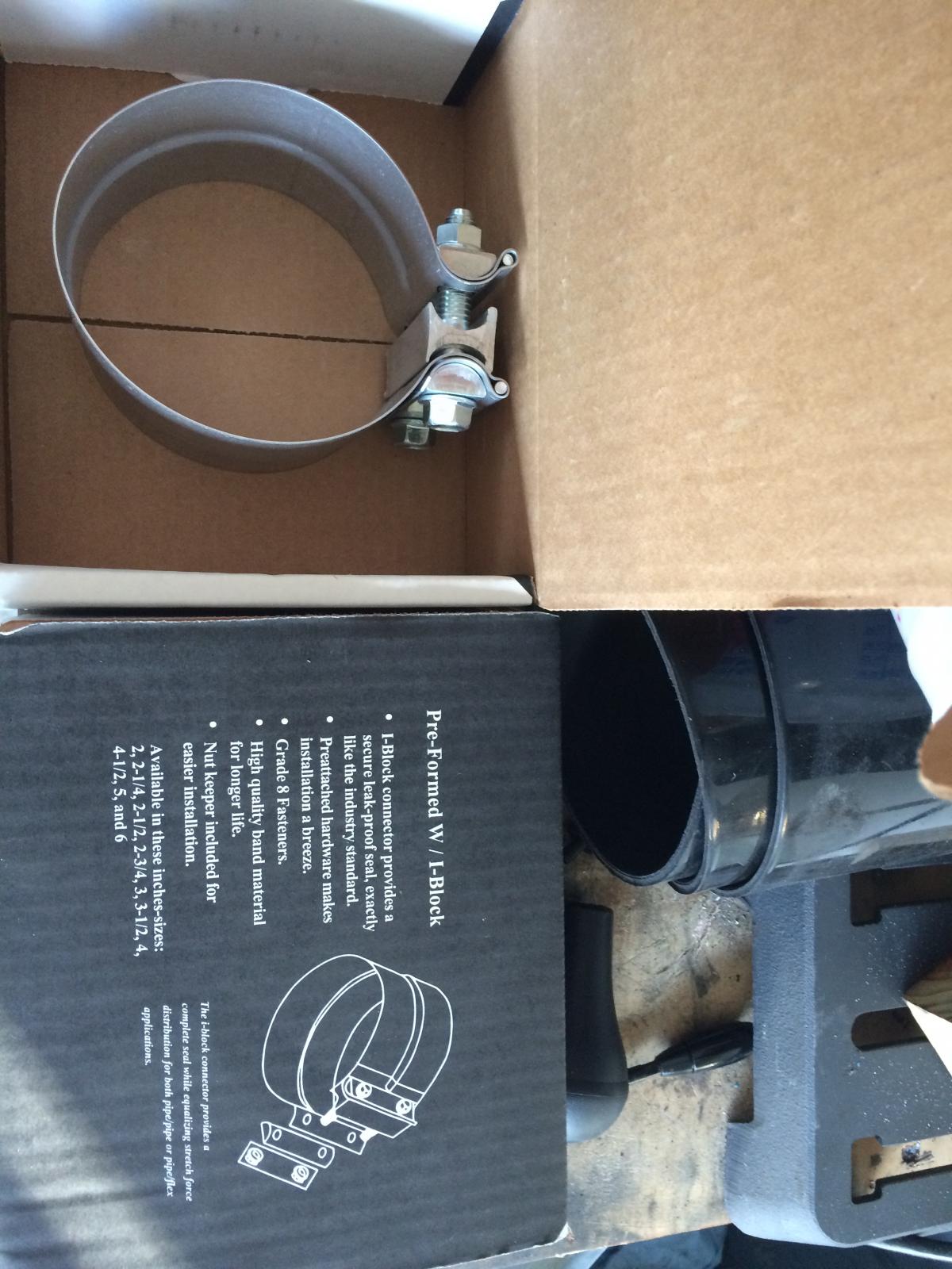
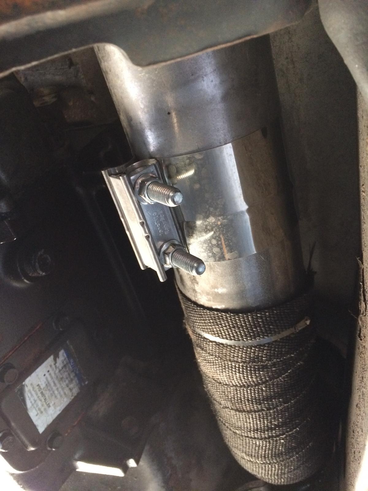
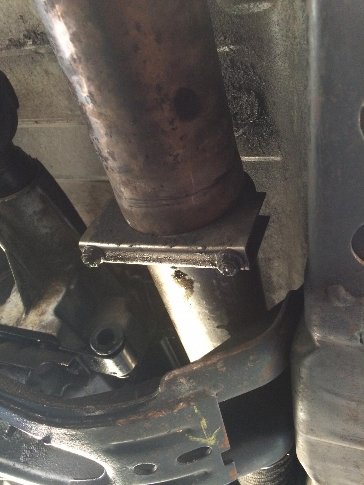
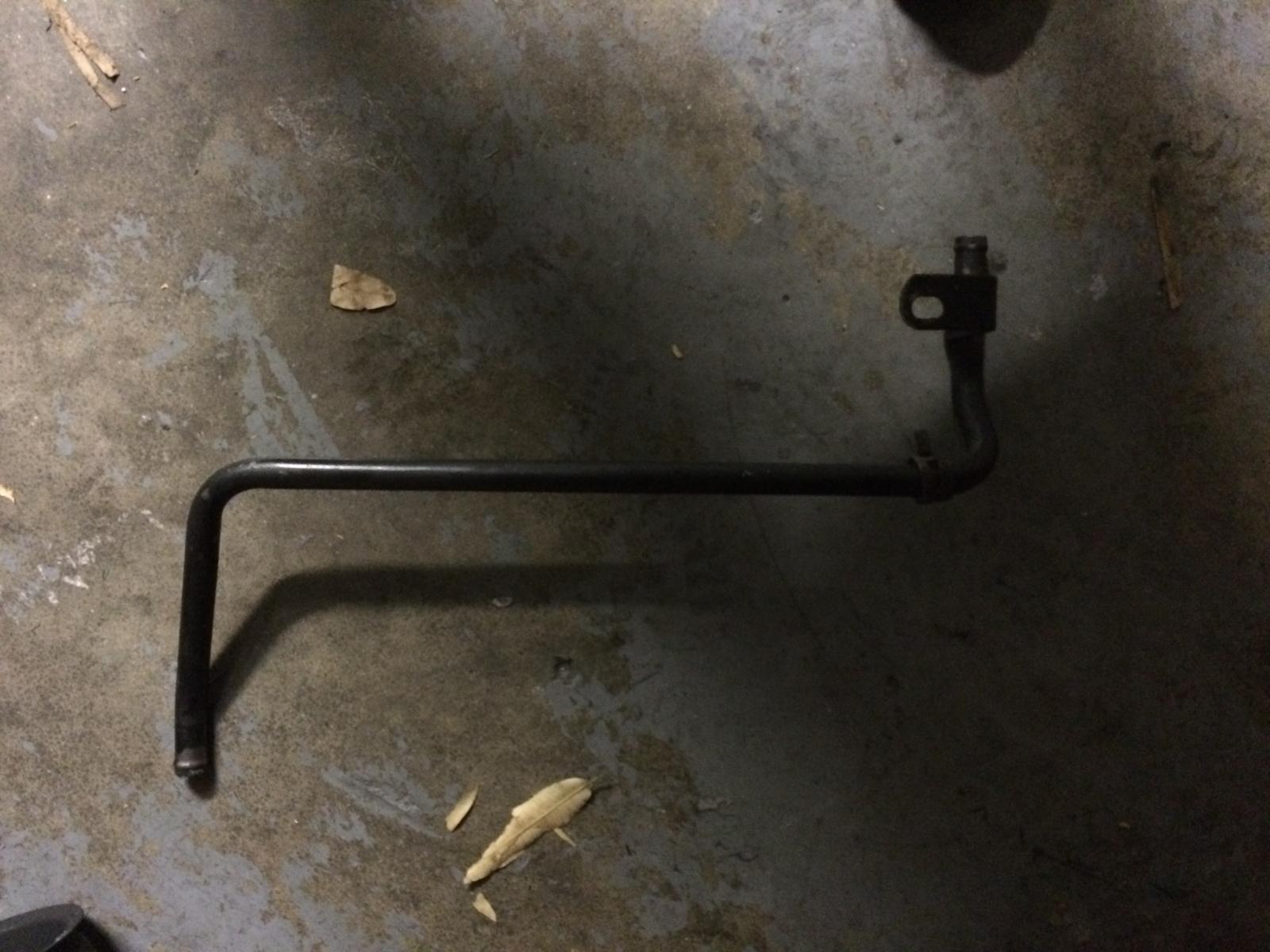
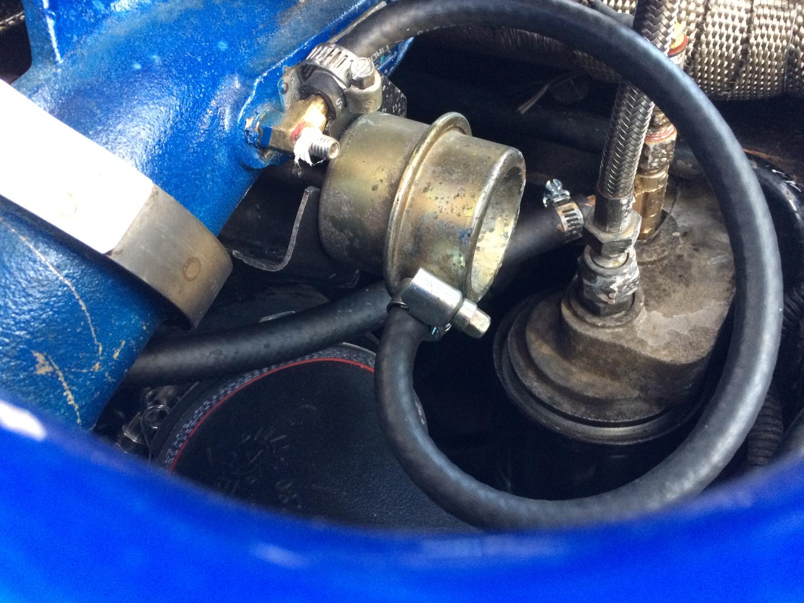
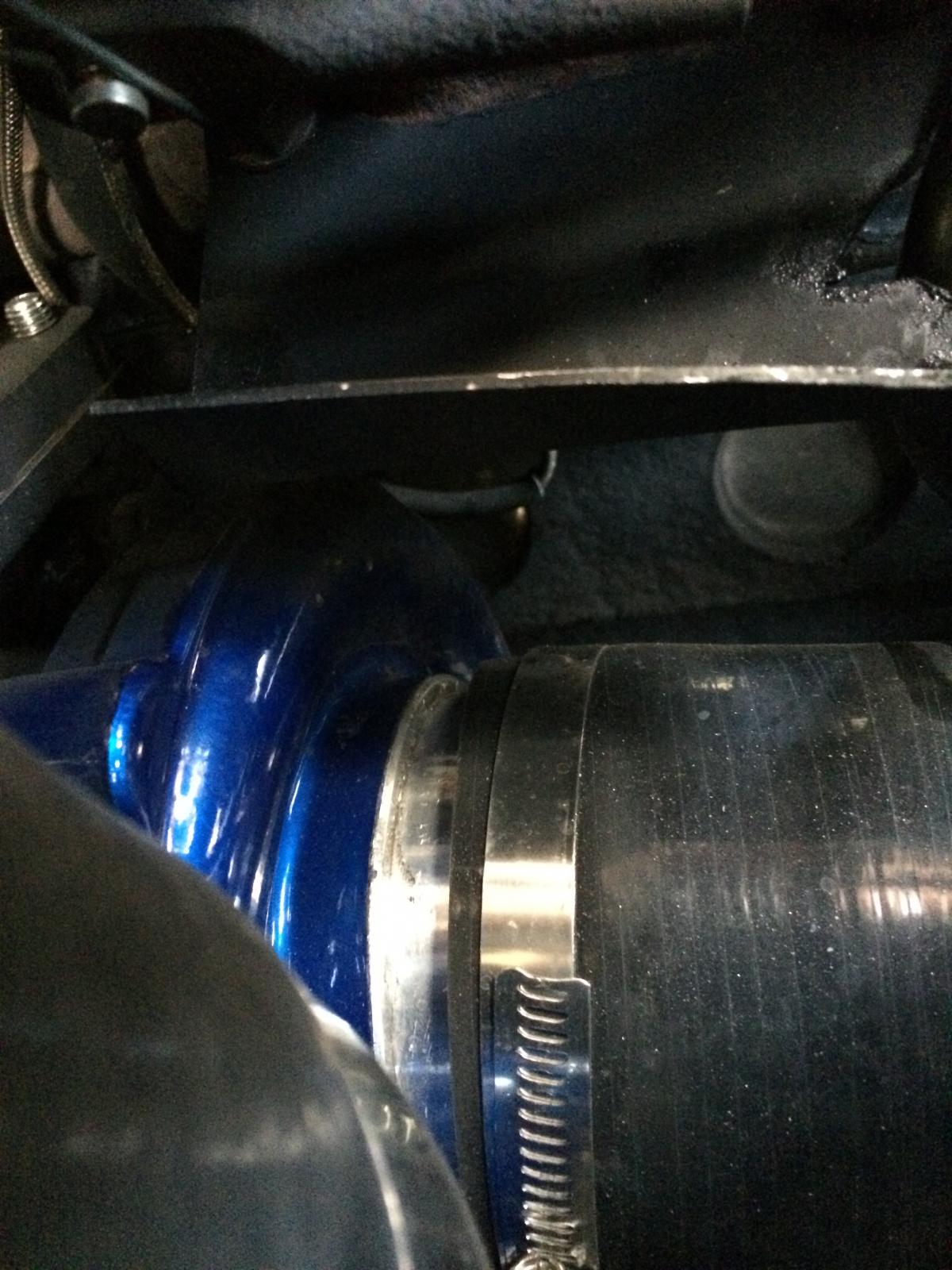
Since you will have to grind off the actuator mount, now is a good time to paint your comp housing if you want to. I had my turbo and pipes come powder coated blue, so it made sense. I also had the T4 housing and center section ceramicoated, so I painted the HX35 T3 housing with header paint as well. Evil fab powder and ceramicoats for free, so just ask for it if you order a kit. After bolting the manifold back in upside down, I installed the T3 spacer, and began final assembly. Tip#3, it is really freaking hard to bolt the S366 up with the HX35 installed. I found it much easier to bolt them up on the garage bench, torque everything I had access to, and then set them in the engine bay as one piece. Problem #3: If you do not grind off the actuator mount from the housing, you can't clock the housing correctly, and the HX oil feed line will not fit. Problem #4: Go buy a spring clamp remover like the picture below. You will thank me later. Remove the Comp housing, for grinding / painting, and its time to clock the center section of the HX35 for the oiling system. If you were smart about it you made sure to loosen your T3 housing clamps and break it loose before getting here. I didn't, so I took it all back apart to do so and then put it back together. Tip#4: It may make more sense just to install the S366 with the HX35 T3 housing first, then install the HX35 center section. I didn't try it this way but I just realized it might make things easier. After your HX35 center section is clocked, you can start modifying the oiling system. I clocked my HX center to about 12:30 position (Feed fitting position), which eased the tension on the line. Now its time for the drain hoses. The trick here is not too long and not too short. the HX35 is pretty straight forward, since you are just deleting part of the solid pipe and replacing it with hose. The S366 is best tackled laying under the truck, where you should have access to everything. The hose there will curve a little but make sure it is not long enough to kink and flatten. The feed line for the S366 is straight forward, but if you are using a your quad trans temp as a oil temp gauge, you will need some fancy 1/8" NPT parts to Tee off the Filter housing. Try routing the hose away from the hot pipe. If you followed the directions, you are probably reinstalling your comp housing now and getting ready to start your truck. The spring clip on the HX35 is in my opinion the biggest pain in the *** of the entire project. I could not find a single set of snap ring pliers that could squeeze the SOB into place, which is why this install took two days (about 10 hours working time total). That being said, make damn sure you clock the housing right the first time. The outlet should point almost at 9:00. If you already installed the new silicone elbow and the cast comp elbow, its easy to clock the housing. Finally, I started the truck per the instructions and followed the S366 pre oiling / break in instructions to the T! My only real complaint about this kit was the air filter setup. the kit comes with a small K&N cone filter, which goes right on the S366 and its close to the block in the hot air stream. I quickly used my old K&N Cold air intake and some Amazon IC parts to make a better setup. I also ordered a T3 Turbo fiberglass heat shield, because I was nervous about the harness and the hood. The kit comes with the hot pipe and down pipe heat wrapped, which is nice. Two things I regret from the install: There is no support bracket for the S366, it just hangs off the hot pipe. I am not having issues, but it would have been easy to fabricate something while I had it apart. His larger kits include a better intake setup and a support bracket that goes to a header bolt. I also regret not heat wrapping my manifold while I had it off. I wrapped the section near the oil temp sensor, but that's it. I found a crack right in the middle of my manifold when I flipped it over, its not leaking for now, but I already sourced a replacement for a weekend that I'm bored. Overall for 1500$ I am extremely happy, and the quality of the fabrication was very good. Waiting on my ARP stud kit and then I'll bump the boost up from 40 psi (quad limited) to 55 PSI, at least until I get valve springs. @Mopar1973Man @TFaoro @Me78569 Is this thread alright?
.jpeg.e99a811d8511e7c23dc6b86ecc1064c7.jpeg)
.JPG.d8d5063c5398034058b9afe382c68b50.JPG)
.JPG.2bebab5f9bede7c659e1eb1b39a19bfc.JPG)
.JPG.02a722910b038cd268aeb5603873d8ff.JPG)
.JPG.e55204e079fd74b4eb266a06ab96ffd0.JPG)
.JPG.a319c83897c17b6767f99b1d5952b2df.JPG)
.JPG.54d0e552ffcd2afc1d69fa4b67c8eb9e.JPG)

-
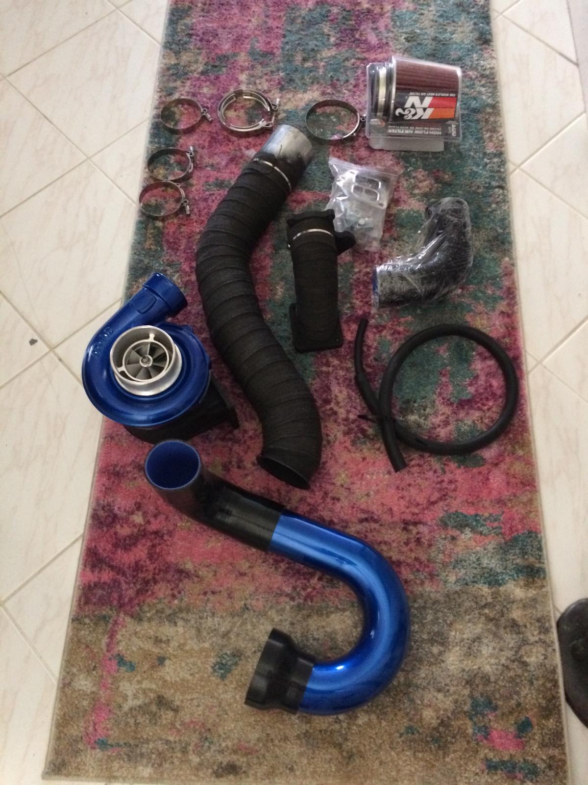
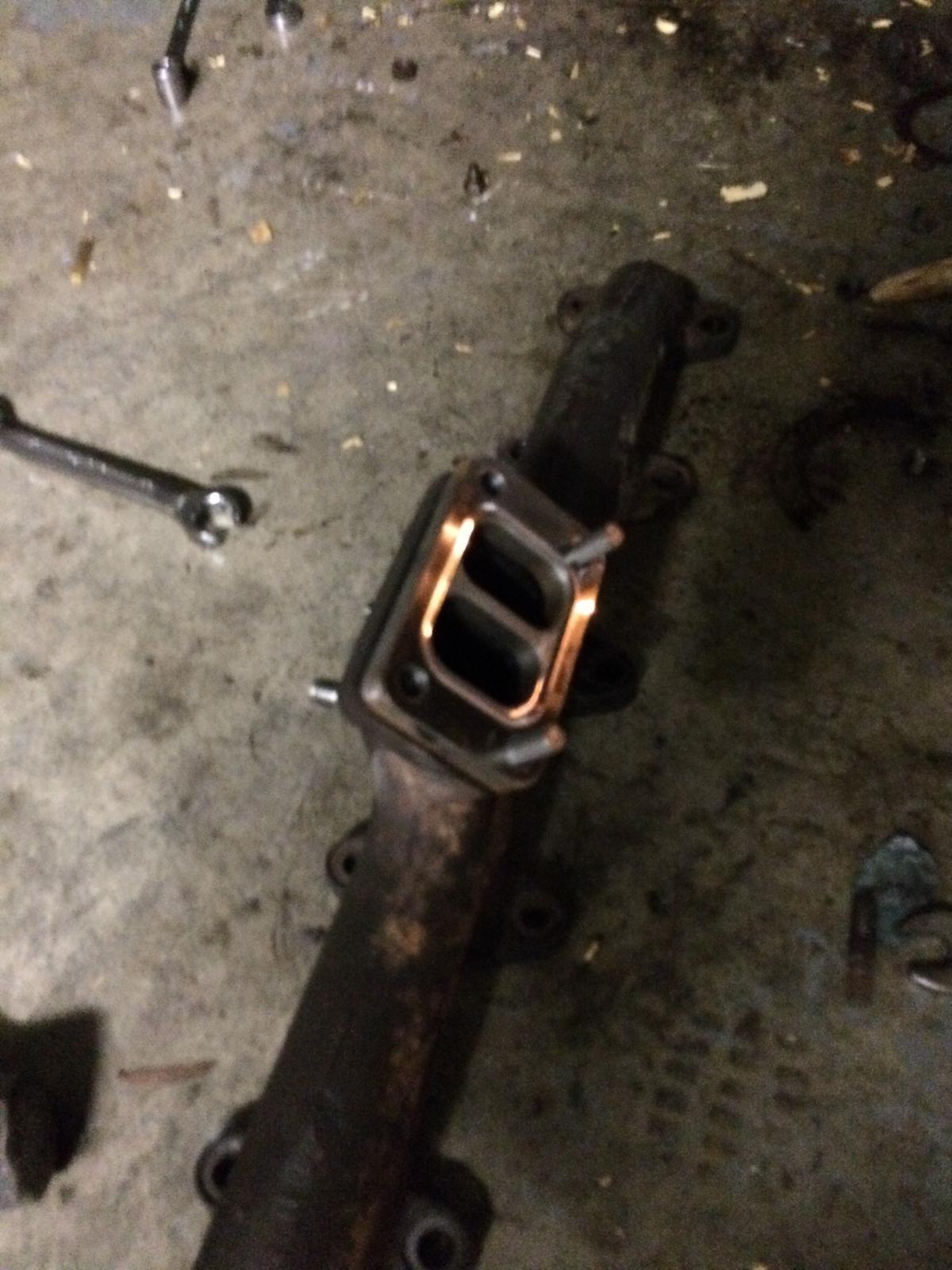
So, I have been running my compound setup for 3 weeks now, and I am impressed on all levels. For 1500$, I have instant boost, 24 MPG, and even when I fuel it like a dragster, The highest EGT I can get is 1280*. Because of my awesome experience, I have decided to share the entire installation and give a few tips for anyone who wants to go this way. The kit I purchased is the Evilfab525 kit, here is the website link : http://www.evilfabperformance.com/shop To start this project I inventoried all of the pieces in the kit, verified the S366 T4 turbo was clean and operational, and then set out on disassembly. Problems encountered here - The factory downpipe / 5 bolt manifold had a bolt already broken off, and another one broke on me as well. Repair involved a drill press, tap and die kit, lots of lubricant, and patience. So moving on, the T3 HX35 uses 4 studs, two on manifold and two on turbine housing. Trash them! This kit requires inverting the exhaust manifold, so the HX35 will be 180* and will require restudding / drilling out threads as required. The instructions provided very good info on this, and the fabricator Riley can answer any questions quickly before you get into trouble. Also you will need to knock out the rear oil drain freeze plug, and chopsaw your HX35 drain pipe for the S366 Drain. Read the instructions on this part carefully! After you have your length of drain tube, here's a tip: you should have 2.5- 3.5 inches of straight pipe. take electrical tape and tape the end you intend to tap into the block, marking a depth of 1 - 1.25 inches. There is nothing to limit the depth, and you don't want to hammer the tube all the way into the oil pan. Also a 1" or 15/16" deep socket slides over the other end nicely and gives you a part to hammer on without damaging the tube. After getting your oil drain prepped, get the hacksaw out and cut off the exhaust pipe about 24 inches forward of the transmission cross member, this gives you room to mock everything up. I cut mine right where the 3.5" down pipe expanded to 4". Tip # 2: go buy 1 or 2, 4" exhaust clamps (if you already have a 4" system) and if you are running a magnaflow system that has a 3.5 - 4 inch downpipe, you will need about 16 inches of 4" pipe to splice to your exhaust, unless you plan a new exhaust at the same time. This is where I started mocking up the kit. Problem #1 the waste gate actuator was in the way. Remove the actuator and with great finesse and care, Grind off the mount from the compressor housing. Problem #2, The heater pipe has a mount which bolts to the exhaust manifold. This does not fit with the manifold inverted.Its also in the way of the hot pipe. You have to options: Delete the pipe and replace with rubber hose, or Cut the mounting tab off. I cut the tab off, because I was being cheap. Now its time to start assembly. I fabricated a bracket to hold the waste gate actuator from 16 gauge plate steel from home cheapo. I used a piece of thin cardboard to template the T3 Bolt pattern, and measured the distance from the flat surface of the actuator mount on the comp housing, to the gate arm. using that measurement, I utilized a Drill press, Sawzall, Bench Vice, and Ball peen hammer to make my bracket. For rigidity, I started by bending the plate 90* in half, and then started on it with the sawzall. After I got it shaped right, I used my little mig welder to put a bead in the corner for extra strength. a bolt works just fine too. you will have to notch your bracket to give clearance for the HX35 oil drain. I painted it with black header paint to look nice and put it off to the side.


.JPG.8c6bde8ea10efc6479003c96e740c19d.JPG)
.JPG.013e685770af09a0a995d17150ae7f25.JPG)

.JPG.ca2d8210cee384edc55a576af459391c.JPG)
.JPG.c05cc7a4cc8469ad6bfa4ac1ffbff800.JPG)

.JPG.53914ec56a54d457e2f4bc9872ed8f39.JPG)
.JPG.45bf98f6649234876689f67e67e38405.JPG)

-
Ive been driving V2.1 the last three days with no issues. Working on my fueling, but Ill be messing with my timing tune soon
-
Are you running factory fuel lines to the VP? I prefer this fitting from XDP XDP Push Lock Fuel Pressure Tee 1/2 with 1/8 NPT port https://www.amazon.com/dp/B01AGMF6PA/ref=cm_sw_r_cp_tai_aqXqybDGFM6H3 my last truck used an AD Raptor 100 in the factory location, so I installed the fuel pressure transducer in the output line to the filter assembly. As as for the plumbing it's simple: exhaust>turbo>downpipe Airfilter>Turbo>cold pipe>Right side intercooler inlet> left side outlet> Boost pipe> Intake horn. do you still have the factory air intake horn? Also, the stock HX35 turbo has a Married wastegate actuator which is on the bottom of the turbo, you won't be able to see it from the top with the air box installed.
-
@BigPimpin, Me is right you definitely have either boost or wastegate leaks. Also you should invest in at least a pneumatic boost gauge and doublecheck it agrees with the map sensor. Honestly it sounds like a blown hump tube or intake horn gasket if the wastegate is ok. Check the IC for leaks too Also, the quad alone is not as much a power adder as it is a tuner, but if you get your air and fuel problems solved, the quad will milk every ounce of power out of it. You definitely need a fuel pressure gauge before turning the quad up though, the VP doesn't live long with 0 psi fuel, and wiretap power sucks fuel. hope you get it fixed soon Do you have the IQuad?
-
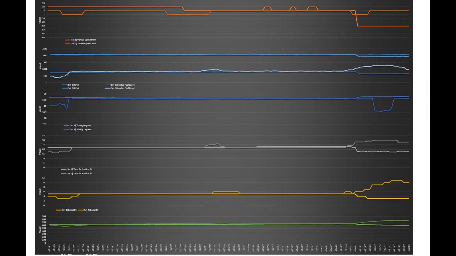
Just Dropping a V2.1 Log here, This is a new tool I am working on, it allows multiple scales and charts, but will always print on a letter size paper. I am liking the new timing curves, have to get used to tuning with it. City mileage has definitely gotten a bump. I averaged 18 mpg sitting in traffic on my way home yesterday, but over 20 on my way home today in traffic. please also see the attached tunes that I am running, if any of you guys want to bump the overall starting % and try the curve let me know, I can plot your tune and send it back to you. I am going to test the three on the chart over the next few days. Quad Tune Calculator 11.22.16.xlsx @Me78569 Regarding the V2.1 how does the new 15* base affect the scaling. For example, I am testing a tune that runs 15*max@53%, does that mean my max achieved timing in the tune will be 23*? that should give me some room to increase the timing for that scale then
-
So that all makes sense, and like I said I am not trying to run a stock map with my injectors, I am just trying to apply some math and science to the "Trial and error" way we have been tuning. I like your description of the new timing "bump" I need to update the quad tonight and try it out. I agree, and the different flow maps for injectors is not great, but I haven't been able to locate a flow chart for the OEM injectors, so as far as precision base tuning, Its just "trial and error", which is fine, but the absence of smoke doesn't necessarily = a good burn, so I am just investing a little time and effort to see if we can produce reusable data that will help everyone learn this tuning. I am seeing some interesting data from the quad on the MPG tune that I'm hammering out, which has peaked my curiosity into the science. I wish we could use A/F ratio as a tuning measurement, because a 5.9ISB @ 30PSI boost is inhaling 17L of air every revolution. I'm going to try V2.1, and see how I like the timing. I'm getting decent mileage with my tune, and the timing was very stable today. Thanks Guys
.thumb.jpeg.8a32aec2daaac1b77a29eb3b52b77505.jpeg)
