

W-T
Yearly Subscription
-
Joined
-
Last visited
Everything posted by W-T
-
OK...from this info I would advise searching for a boost leak. The MAP code is valid and with a stock truck you should be able to see at least 20 PSI of boost. With only 5-7 PSI max the sluggish response would indicate a very large leak in your system. You needn't spend time rebooting the ECM/system at the present time. The main focus is a mechanical error allowing pressurized air to escape the closed system. With a leak that large I'd begin with a squirt bottle filled with water and dish soap and look for bubbles at all mating joints of the boost system. Your waste-gate should be fully closed at idle and I am not sure of how you're set up but, do you have performance enhancements where you've J-hooked your waste gate to allow additional boost levels beyond 20 PSI? If so, I'd attempt to see if there is any extraneous aspects to the control arm of the waste-gate that would interfere with full mechanical closure of the gate itself. This is a messy and difficult chore to observe due to the location of the waste-gate actuation arm but, you must assure yourself that the gate can fully close. A waste-gate open just a small amount will not allow boost to be built and set a MAP code quickly. I acknowledge your observation of the oil pressure gauge...let us first correct the poor engine performance aspect and get this beast back to normal operational levels. Not being there with you I might guess the idle aspects of this CTD could be suffering and perhaps this leak is large enough to curtail correct idle RPM and contribute to low oil pressure indication. BTW...do you still have a "water in fuel" indication? Billy
-
Mark, the P1693 is only an indication of a "companion" code. It just means there is another code within the system and actually it's not a real concern. it's just the way our system works and it's redundant for it to tell us we have a code. I too see it when I hit 30 PSI of boost, and the P1693 shows up along with the code indicating "over boost". I always clear this prior to taking my vehicle into the service facility for the bi-annual Smog inspection here in California. Now, your P0237 is a MAP sensor code, Manifold Absolute Pressure, this could mean high or low boost via your turbo in run condition. I'll assume your info regarding "water in Fuel" came up just after your good deed in helping out was completed? I can not see how allowing someone to apply jumper cables as a courtesy to another driver to cause your MAP sensor code and water in fuel to occur immediately after doing so. I'll go out on a limb here and say, NO on ECM failure. You stated that you can't clear the code(s) and I'm assuming this is once you clear them and start the engine for a test drive, the error codes reappear? Are you able to monitor boost? Is it acting normal? Does the truck feel normal on acceleration? Are you seeing lots of smoke on hard acceleration? Sorry for the trouble but, the old adage of, "No good deed goes unpunished" may hold true here. Allow us a little more of your observations as we move forward with this puzzle. Here is a scolding...never allow anyone under the hood of your CTD Cheers, Billy
-
@Sycostang67It is always best to obtain a power source that would provide twice the amount of current that you'll need. Rule of thumb, avoid running a generator at maximum level once you've selected all the power devices you will operate in a must do scenario. This also allows you to select what is NOT necessary in situations where the priority is AC on a hot summer night. Dan's list (@IBMobile) is very comprehensive and common sense tells me that operating a washer/dryer at 10pm on a 90* night in a RV park is not a sound decision. You should definitely consider the "Inverter" style generators, unfortunately the choice of manufacturers is limited in this category however; from a "noise" standpoint attempting to operate an analog generator in many public parks after 8pm will bring attention from fellow RV neighbors and perhaps park authorities. Yeah, the Honda EU series inverters are the most civilized considering noise but, they are also the most expensive...the old adage applies, "You get what you pay for". The newest Honda EU platforms are fuel injected so elevation above Sea Level is not an issue and Honda has now included an APP where you control Start/Stop and estimated fuel Run Time data. This becomes fully controllable via your smart phone. I realize storage space is a key aspect in a RV environment however; purchase the largest generator (inverter style) you can stow and operate conveniently. You must also "tame your Air Conditioning" by applying a "Soft Start" controller. This is the most important aspect to operating any modest sized generator regardless of design. MicroAir.com is the most sophisticated device to accomplish this task! It is NOT cheap and provides cutting edge "Zero Cross Over" current engagement technology. This company started in the RV industry several years ago, specifically to render high current demand RV AC units to "Start and Operate" with modest power supply sources. Examining the data plate on your Air Conditioner will reveal the "LRA" Locked Rotor Amperage. This is the initial "peak current" demand required to start the compressor. The device requires programing to "learn" the demand of your AC compressor. Once the device is installed, you merely "start the AC" five times in sequence and allow the onboard algorithm to "learn" the curve of start-up current demand. It's all very simple to do and the results are quite surprising. The uncivilized manor of an "induction alternating current" motor engaging current demand at the "zero crossover" point in a 60 Hertz wave form is such a beautiful thing to observe. Obtaining your "LRA" specification is the key to selecting the "model number" of the MicroAir controller required in your application. @AH64IDis also familiar with these controllers, as I've found a thread where he was referring to such devices. Please NOTE: The more desirable Honda Inverter platforms can be operated in parallel and come equipped to be connected via "optional cabling" between the two individual units. You needn't worry about "phasing" the two devices, as the two separate "inverter outputs" have a 70 microsecond delay at the "parallel ports" to allow perfect "phase" coupling to occur hence; both units sniff each others butt before they combine a sinusoidal sign wave output. Theoretically, (I'm spending your money for you) if you were to obtain two EU3000's, both units are quite compact, you'd have a potential of 6Kw available. You'd be able to operate on a single unit and when late afternoon or early evening arrives, you would look so cool as you open your smart phone, press one button and bring an additional 3Kw online because, your lovely wife looked out the door and indicated she wants AC to cool the coach as she prepares that lovely evening meal in the kitchen. You would NOT be taxing your generator system because it's operating at only 60% and she can run the blender for the Margaritas when the neighbors come over for cocktails. Oh...let us not forget the 55" flat screen with full sound system because all the campground kids are coming over to watch Harry Potter. AND WHY is this all happening at YOUR camp spot?....because the Honda inverters are so quite, a normal conversation, at normal audio level, is all that's required, as the Honda power plant is ONLY ten feet away. Gosh, what a beautiful, peaceful summer evening with family and friends. Anyway...MicroAir controller and Honda EU platforms allow you to be tactically superior in a "must do" scenario. Besides that...it is just down right bitchen! Golly, I love spending other peoples money. Cheers, W-T
-
Stu, Wow! Voltage Standing Wave Ratios...indeed! I find it so very contrasting in the mix of individuals who haunt this web site with exceptional backgrounds...it's so funny in generalities, where some people would think we're just a bunch of grease-monkeys playing with diesel pickup trucks. The sophistication one requires to be competent in this days automotive environment is pretty demanding and just assuming we are all a bunch of hicks makes me laugh. Your experience and background in Aviation is an outstanding foundation...again it's so cool to have an affiliation with such individuals ! Annoying...not in the least...bring it on Thanks W-T
-
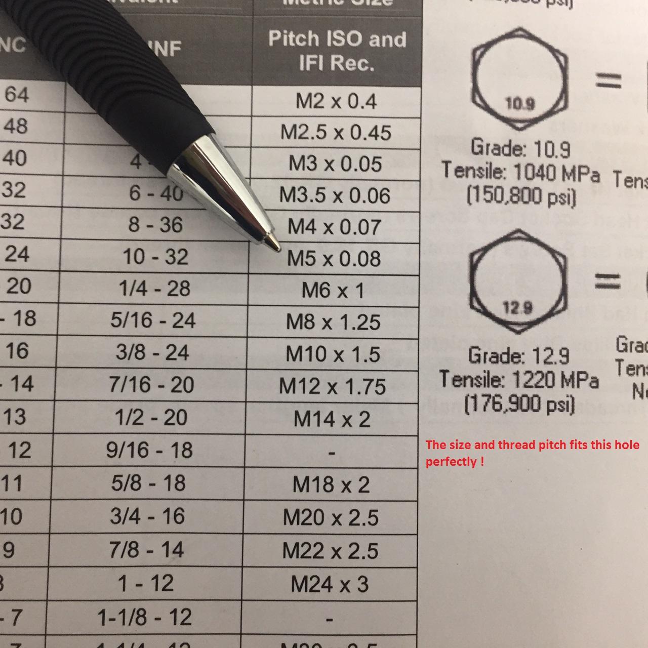
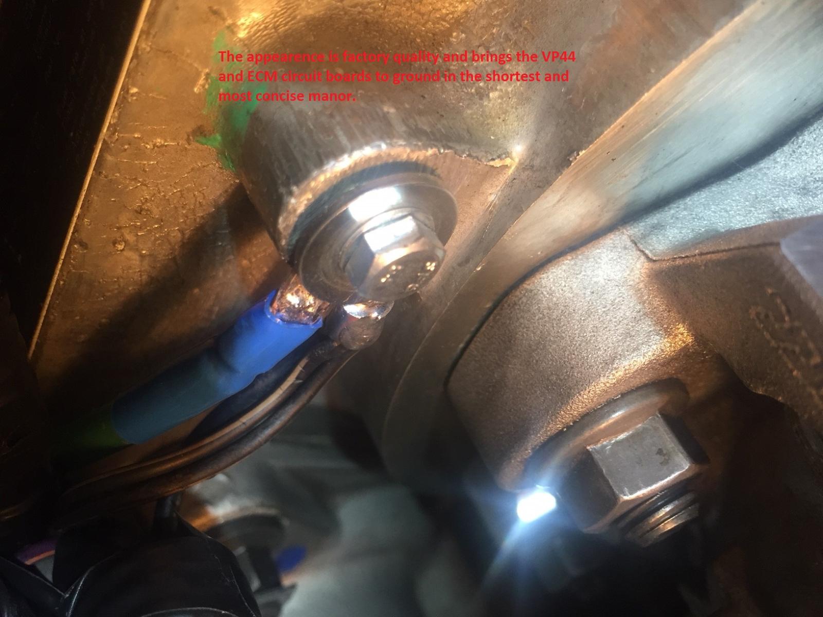
I had seen a few reports that the unused hole I'd selected for concise ground would accommodate "other" sizing. As long as you have a good firm torque setting without "wobble" in thread mating you should be good to go. It is interesting to see such reports and causes me to question what this unused hole was machined for in the first place. My initial selection worked well for my application and the 10-32 thread count, threaded up perfectly. We are dealing with an aluminum housing so, caution should be observed here to prevent damage due to miscalculation. @Stubillyyour attention to the details of many contributed articles on this site will certainly allow you to avoid some of the unfortunate pitfalls regarding the 2nd Gen platform. Your successful application of these "Mod's" have been performed by a large majority of the participants and feed back is always appreciated. Over time, I've seen some variations by some members who've elected to short-cut some rather important aspects. May I strongly encourage you to fully double-strap your battery cells. It is very critical to have zero error here, This imperative aspect assures "parallel compliance" between the two individual cells with NO ERROR. Yes, I realize grounding to the frame and engine block makes this seem redundant however; "double-strapping" assures absolute "mirror image" of a single battery. The PCM is monitoring the temperature of the Main Battery (drivers side) for the demand of charge rate (from the alternator) at a given temperature and DC load. It is imperative to have that data be purely absolute, so, do not rely on extraneous connections to frame or engine block, all being of dissimilar metals and condition of "the various connection points" to provide "absolute" reference to the PCM's ability to determine "what" charge rate is to be distributed to the storage cells. All of us have our trusty Multi-Meters, DVM's or some such devices to determine voltage and or "resistance" (Ohms scale) in making a "quality" measurement. Please note, these devices have major limitations, especially regarding "resistance"! All of these handheld measurement devices are limited to .2 ohms at best. Many handhelds DVM's are are quite good at measuring large values of resistance however; the ability to observe small values or changes can not be measured due to the inherent design of the given device. Your typical handheld Multi-Meter or DVM displays .2 or .3 ohms of resistance when you touch both probes together. This is showing you the very bottom end of the resistance scale of the device. Factually, when you touch both probes together the display of the device is showing you the actual internal resistance of the device itself. Basically, it is sniffing it's own butt ... sorry for the colorful dissertation. This limit of .2 ohms, is in actuality, rather large in value. I make this point in correlation to the thermistor-sensor at the Main Battery tray where physical contact between the Battery and the sensor takes place. The circuit within the PCM is monitoring the "varying resistance" of this sensor at a clocked rate of perhaps 800 times per-second, for every half degree C (Celsius) in change or variation of temperature. In regard to trying to measure a varying resistance below what our trusty handheld DVM's will do, an advanced Laboratory Technician or Engineer will resort to a device called a "Wheatstone Bridge" that will measure extremely small amounts of resistance in scales of less than .001 Ohms Now!... we are working at the level our PCM is measuring in accordance to the exact charge level our 12 volt storage cells require or DO NOT REQUIRE. I am NOT suggesting everyone through their DVM's in the trash. Knowing we are limited to the design perimeters of our test instruments and understanding the limits of resolution should allow one to follow a practiced discipline of not following mediocrity. Daimler/Chrysler produced several aspects of mediocrity into these platforms and the enthusiasts who participate here are discriminating individuals looking for corrections. Hence, when you measure a DC circuit for intrinsic resistance or quality of "conduction" and a circuit that is measuring very small parameters in temperature, that rely on an absolute error free DC resistance path, between a pair of large storage cells where only one baby has the thermometer in it's butt....DO NOT TAKE THE LONG PATH HOME. (My respects to Super Tramp, Breakfast in America) DOUBLE STRAP a true Parallel configuration between the two storage cells and allow your PCM to see a perfect mirror of both cells with NO questionable path to an engine block or frame that can't be measured accurately. Perhaps, the loss of alternator charge error, the loss of boiled off batteries, the procurement of a replacement PCM due to mediocrity in budgetary DC wiring on Daimler/Chrysler's bean-counters demands...gosh there is a lot of blame to go around for the buffoonery. Members who've lost batteries and alternators in very scary scenarios @JAG1 as reference can share observations. @dripley...as you can see, I'm annoying the hell out of everybody! Cheers, W-T
.jpg.1ce1c88fd44a45ba182d54aad629ff0d.jpg)
-
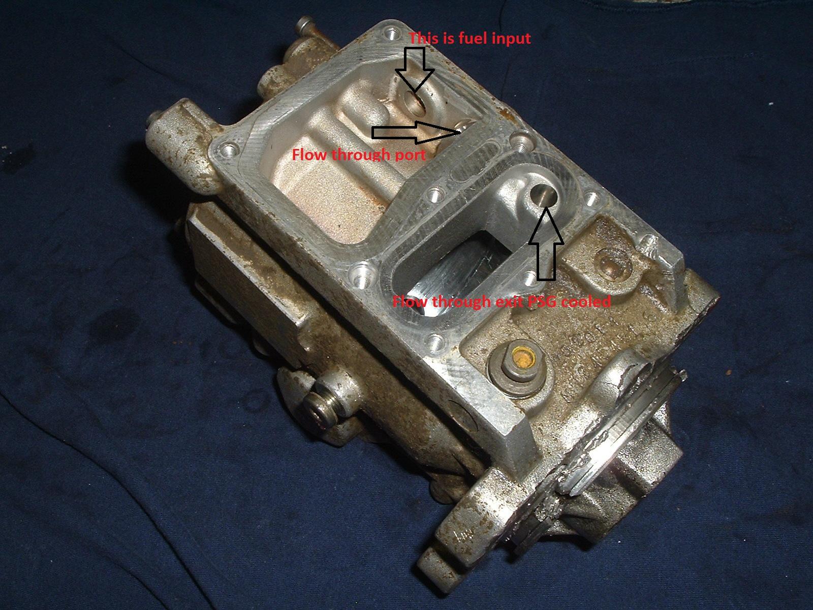
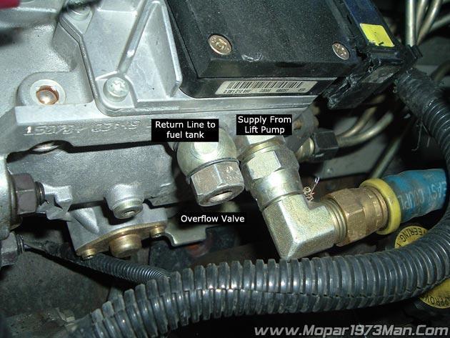
Now this is revealing... Am I wrong to assume the fuel in "feed-boss" is flowing fuel into the chamber directly under the PSG at the level of pressure provided by the lift pump? In reference to @Silverwolf2691 supplied photo (with zip-tie) it appears fresh fuel first enters this chamber, fills and then exits (follow the zip-tie) to the tone-ring chamber. This flow then quenches the entire VP44 pump body for pressure manipulation. This photo provided by @Mopar1973Man verifies the feed aspects. In my experience of changing a fuel filter (Air Dog frame mounted) I always remove my trigger lines from the harness that originally provided DC to the factory lift-pump configuration. I use that trigger line to power my relay and provide PDC, DC to my Air Dog in the standard mode of operation. Changing my fuel filter I take a pair of alligator clip-leads and directly power up my relay closure to force the Air Dog into constant run mode. This fills my new fuel filter and burps the air from the flow-path and alleviates all hydraulic fuel/air issues prior to actually starting the engine. I've done this for years and the method is flawless. My Cummins starts on first key closure every time. My observations of the "time element" that it takes the Air Dog to purge the system following a filter change is not more than one minuet maximum. I've actually allowed this configuration to static run for as much as 5 minuets just to see if my water separator has any water to glean due to long periods of none operation and alleviate the possibility of condensation occurring in my tank. Yes, I am also observing my mechanical fuel pressure gauge holding a level of 17 to 18 PSI during this event. The volume provide by this Air Dog is substantial and is plumbed through large inner diameter tubing to feed the VP44 directly. The "air separator" configuration of the Air Dog is plumbed back into the factory fuel fill tube via the Air Dog supplied splice-in manifold. Yes, removing the fuel-fill cap you can hear copious amounts of fuel-flow being fed back to the tank. I also have the "draw-straw" modification configured as per @Mopar1973Manalong with modification of the "fuel-return" basket within the tank. Yes, I avoided allowing "hot" fuel to be redrawn into the system. This aspect is just common sense... I have NOT experimented by measuring the volume of fuel being returned to the tank as others have shared in this running thread. I bring this forward ONLY because of my experience of "dead head" priming or purging the system after a fuel filter change out. With the experienced examples being shared here, I'm quite puzzled to read about the dismal minimums of fuel being visually returned to a catch-bucket. Again, I'm thinking out loud here... In viewing the photo above from @Silverwolf2691 with the very revealing zip-tie flow path and countless discussions of the functional aspects of the "OFV" over-flow-valve and it's inherent properties as it functions... I must ask how the return in an experimental "open bucket" return flow be so minimal? I admit, I've never pulled my return line and force activated my lift-pump to make such an observation in a "no run" scenario but, the simple empty fuel filter procedure I use has lead me to believe the feed through volume has merit. My intuition with a pump sinking nearly 8 amps with a factory rating of 100 GPH holding 18 PSI is substantial. Simple math shows me a flow rate using Air Dog spec's of 100 GPH to be 1.666 gallons per minuet. That's enough to make a real mess on the shop floor if one was not paying attention! So guys, gals...I'm not specifically calling anyone on the carpet here. @wil440is sleeping right now (4pm west coast time USA) when he says it ONLY piddled in the bucket and others also had similar observations... I have to review the shared data? Further more, all the "old time" data floating around being acknowledged as Biblical scripture that "there is NO flow through" when the VP44 is not in running mode hence, no fuel circulation. With the photo @Silverwolf2691supplied, I must return to my initial exuberance of "the possibility" being valid. Previous shared observations causes me to question the driven PSI levels of the given lift pump and the operational aspects of the over flow valve? I'll dirty the water further, these aftermarket electro-machanical lift pumps do require current to operate properly, at 10 amps nominally and a distance of 8 to 10 feet away assuming frame mount configuration voltage drop due to I*R losses must be considered. Prudent selection for NO error would be #10 gage stranded copper wire. This pays off well for those of you in colder environments during winter conditions. I'm back to considering a "timed post run DC controller" to allow flow and battle "heat soak" syndrome. I know I've not won favor with the mechanical fuel pump crowed however; don't throw away your old Carter lift pumps...they too provide a purpose in this possible venture. Cheers, W-T
-
Turbo Terry, I don't know what to say here. Why would a repair facility turn down work? These 47RE's are quite common so the reasoning eludes me. I hope your crew is successful, please post with additional data as you proceed. @Dynamic is certainly a notable authority.
-
This is interesting @Silverwolf2691 and I need to learn more about what you've brought here. This could be a glimmer of hope. Indeed...I agree the pump at rest will not allow full flow-through and the static tests run by several members here are quite revealing with dismal flow rates being so minimal. Again, thank you all for the quality feed-back on an old subject matter. I'm sure we'd all enjoy an additional "cool-down" procedure that may increase longevity and I fully agree with @Dieselfuture that achieving 200K miles or better is certainly acceptable, along with @dripleyreporting better than 275K...gosh I guess I maybe asking for too much. But, again there is no harm in attempting to find a method where post shut down of the engine would allow for continuous flow of fuel to aid in abating "heat soak" conditions that we all agree does exist... Too bad this was not a consideration by Bosch in the initial design and I only mention this by guessing how many VP44's were replaced due to PSG failures that could have been avoided "if" a simple post-run cooling flow had been incorporated to begin with. Being involved with this site containing other like minded people researching "what if scenarios" is quality therapy for me. I complement all of you and your wonderful affliction of "Excessive Compulsive Disorder" in the pursuit of technical excellence... it gives me a feeling of being at home. None the less...I still wish to discover an excellent video presentation (preferably in English) that really shows the exact fluid flow characteristics within this pump. Having worked in the industrial pump industry for many years I understand the proprietary cautions of Bosh NOT wanting full disclosure of the working structure. I also experienced such disclosure cautions in two different companies even though protection clauses were in place. (China is a problem) Again, Thank You all for the added information. Cheers, W-T
-
Hey @Silverwolf2691 thank you, I wish I had the skill in Spanish but, I can tell this presentation is certainly worth while. I know many of us have combed over the internet for many years gleaning as much information as possible regarding the VP44. My general observation in an overall sense leads me to believe the Europeans and Latin countries appear to have a more in depth understanding of this pump. I'm not saying our diesel enthusiasts here state side aren't up to the task but, the real meat and potatoes backyard mechanics overseas are certainly resourceful. Perhaps, the financial challenge they face in regard to "replacing" a VP44 in questionable condition must be carefully thought out prior to laying out the cash. I'm not fond of the cost myself but, when I see a Russian fellow tearing into a circuit board on a VP44 and diligently attempting repair (some procedures are brutal) my guess is, the poor guy has to due so because he can't afford the financial burden of simple replacement and I certainly applaud his focused dedication. Jokingly, I must add that my wife knows nothing about diesels but, she's watched my antics over the years and when she hears the term " VP44" she arms herself with a frying pan and I'm looking for the nearest exit... This entire VP44 subject matter has loomed large for over twenty years and I'm sure many experienced 2nd Gen enthusiasts have read volumes on this subject and many are possibly bored with the topic however; being that this community is an inquisitive gathering of like minded people I appreciate the continued banter. Finding @MikeH bringing forth a good video and @Great work!adding additional observations in "function" tells me good minds are still pondering the subject. Why am I jumping on this band wagon? Because I want to know the exact fluid-flow characteristics within this pump and possibly find a reasonable method to address longevity. Contributions over the years are helpful and the work of @Mopar1973Manindoctrinating all of us to fully adopting the "lubricity" aspects of fuels available that changed shortly after many of us purchased these trucks made a key mark in overall longevity. I believe all of the 2nd Gen owners "who are in the know" dope their fuel accordingly. So...I appreciate the contributions coming forth 20 years down the line and I must admit, the methods are certainly much more sophisticated and worthy considering the time it took to achieve worth while results. I'll stop being cryptic, I wish to find a method to allow fuel to circulate for a period of time after shutdown (hot condition) that would partially alleviate the "heat soak" for the electronics on the VP44 I'm just think out loud here... I know of the aftermarket "fans" blowing air on the VP44 housing...this is old subject matter and isn't my pursuit. I can think of many diesel enthusiasts going back 20 years who have partaken in such topics on other websites where such projects were being bantered about. I guess I'm just hoping to draw out the "thinking minds" who may have additional information and experience along this topic. Heat is our enemy in nearly all devices we work with or operate...I think there is room for advancement here. The manual transmissions have aftermarket "coolers" that allow additional fluid to be incorporated in overall volume...automatic transmissions have deeper pans to allow an additional volume of fluid, both of these examples contribute to additional cooling. The chamber on top of the VP44 that is filled with circulating fuel directly below the circuit board to skirt away heat during run time is already there. What if there were and "extension" housing sandwiched between the circuit board and the VP44 body to allow for additional fluid volume? What if there was a timed circuit ( a simple 555 chip) that allowed the fuel pump (lift pump) to continue to run for a period of time to skirt away heat "after shut down" with incremental "run time" being manually adjustable? What if this hypothetical "extension housing" was equipped with "thermo-electric Pelter Junction" devices to be activated on a timed basis to function for a period of time after the "circulation" period had timed out? This simple aspect would assure standing fluid within the wetted chamber would drop "heat soak" static temperature an additional 10F. Take a look guys and gals..."Pelter Junctions" are very inexpensive low current solid state wafers...the efficiency of these trick devices have advanced dramatically due to the field advancement of the photovoltaic panels. Sorry for my exuberance in theoretical possibilities, I do not mean to pontificate, I wish to stir the senses of diesel enthusiasts and gain knowledge from them. @Haggar, @KATOOM...do you think this could be a worthy investment of time?
-
Nice contribution @MikeHI don't know who these fellows are but, it's nice to see a tear-down presentation at this level. This pump is certainly a dual stage series configuration where the vane-pump is a continuous positive displacement of volume that feeds the piston(s) "single-action" displacement for increased pressure delivery. Both operating in series and operating like an amplifier to increase pressure as required. The output, being small pistons, would not carry volume however; the static pressure increase would be substantial compared to a single stage vane pump running in an open ended configuration. It's the capacitance or volume of the first stage providing copious amounts of fuel to allow the second stage to deliver the peak-punch or injection interval that is required and leaving the additional unused fuel as a coolant transfer medium. This brings me to the question of the "slightly glossed over" explanation of the "diaphragm" in the flow path? I would be interested in seeing a visual presentation of the liquid flow within the pump under normal operation to clarify the properties or action of this diaphragm. I've assumed this component is operating as a buffer stage between the higher pressure piston action and unused fuel (at high pressure) following an injection event being returned to follow the next event. In design, fluid dynamics become messy when one stage is interrupted or back-fed "positive feed-back" from a down stream source. The eddy currents could cause havoc in a high pressure closed system resulting in undesirable dynamic hydraulic phenomena. This video presentation stipulated the diaphragm is operating as a buffer stage between the high pressure output and the driver stage (vane pump) and this realization has caused questions to my initial understanding. Good stuff MikeH... it's fun to ponder such designs. Gosh this pump is certainly sophisticated! BTW...seeing the working components and the minute travel and physical changes during the cycling actions really allows an appreciation for clean fuel disciplines and additional lubricity in our 2nd Gen platforms.
-
Turbo Terry, I'm sorry for the poor response from from various automotive repair facilities. Fully accredited shops are certainly difficult to find these days and electrical issues are unfortunately being met by less than qualified individuals in an increasingly sophisticated electronic arena. You have successfully found the component that is sinking excessive current and opening the protective fuse. The solenoid is the bad component. @Mopar1973Man has directed you towards the next step of dropping the pan to gain access to this solenoid. Your observation of Pin 21 at the PCM being 33 ohms is not focused relevance. That DC resistance being measured against ground with your DVM is the intrinsic DC resistance of the internal circuit of the PCM. It is likely this output never sees direct ground because it is connected to another component in series and it too has lumped DC resistance and in a series DC circuit, resistance would add and of course increase resistance. a simple example would be expressed in Ohm's Law of I=E/R a basic resting voltage of 12.6 volts so... 12.6 divided by 33.3 ohms = .378 millamps In power we would see it as P=E*I or power = Volts x Current so... 12.6 x .378 (mills) = 4.76 watts this is a very small amount of power being dissipated to ground...let's just call it around 1/3 amp NOW...your analysis reveals a very different set of values in the equation. Ohms Law for Power is P=E*I so 12.6 (volts) x 10 (amps) (your 10 amp fuse) = 126 watts HOLY COW !!!! This reveals your RESISTANCE of the solenoids internal resistance. Ohms Law R = E/I or resistance = voltage divided by current (amps) so 12.6 (volts) divided by 10 (amps) = 1.26 Ohms HOLY COW !!!! This resistance is almost becoming a perfect conductor with a very small resistance. A good piece of copper wire has very little resistance. You have already found the answer to your question, the question in your mind of "how can the (wires) short together"...it is NOT the wires it is the integrity of the solenoid's internal structure allowing a (short) pathway to ground. Your own research, your own two hands, and following the procedure has uncovered the faulty component in your DC circuit. By the way, you should instruct your selected repair facility on how to diagnose this and become a better shop...you Sir, are a better technician then they are !
-
OK @Turbo Terry good job in procedure and this certainly narrows the focus to the suspected solenoid being at fault. Previously, you mentioned purchasing an additional wire harness that has this multi-pin connector, and being you have now verified the actual component, I hope you're able to recoup the expenditure. and obtain the solenoid. Why this solenoid failed is unknown however; perhaps @Dynamic would have incite as to what may have contributed to this condition. Of course knowing where this device is located and knowing this is a quasi hostile environment brings several possibility's to consider. Being that this 47RE was prepared by DTT I'll assume Bill Kondolay's procedure is a sound application in regard to keeping 3rd and 4th gear lockup electrically coherent in the scheme of reliability and longevity. I am not questioning the integrity of DTT's procedure...the failure of this solenoid in a wet hydraulic pressurized, high temperature environment could and can lead to sporadic abnormalities if internal pressure seals fail and allow hydraulic fluid laden with micro conductive metal particulates to cause an undesired electrical current path...hence, a blown fuse. I do see your photos with contamination of the critical multi-pin plug...may I suggest the use of WD-40 in an aerosol can to liquid-purge the small pin area and compressed air to fully clean the electrical working surfaces prior to reinstalling the plug to your new solenoid application. WD-40 is an excellent product for such purposes, keeping in mind it is a flammable liquid solvent in nature so...compressed air is required to alleviate any puddles of liquid hiding in small crevasses prior to electrical current applications. You did very well in this task...please let us know of your final outcome. Cheers
-
@dripley I didn't know this was involved in the circuit and you just taught me something. I was focused on the 10 Amp fuse and the peripheral circuit only because I didn't review the actual current flow. I must say thanks, and I hope the information assists Turbo Terry. I'm regretful having lost my Factory Service manuals and I feel I'm flying blind...it is curious that a relay is in series with this solenoid and a 10 Amp fuse would be down stream of the relay contacts...I'll stop guessing how this circuit is providing current to the solenoid and refer to the schematic. Dripley, you schooled me...thank you
-
@Turbo Terry your post states I assume this 10 Amp fuse is in the PDC (power distribution center) (PDF ?) please tell me what fuse you're specifically identifying? I apologize as I no longer am in possession of the Factory Service manual however; I do know Mike Nelson has certain documents available for review and I'll do a little homework on this in order to help you. First of all, having a 10 Amp fuse open immediately when the key is "turned on" is very alarming regardless of "what" circuit is being supplied by this fuse. Please help me here. P0753-Trans 3-4 Shift Sol/Trans Relay Circuit I need you to clarify your observation here..."relay good" and "horn test"??? The CODE PO753 is specific to your transmission only. I will go out on a "hunch" here and it is not my normal way of doing so however; This "wire harness and plug" you've brought into the subject matter...if this plug goes directly onto the 47RE please unplug it, replace your 10 Amp fuse and turn your key to the on position and report back on the status of this fuse. I am ONLY guessing here on your behalf but, if the fuse "does not open" in this TEST, it will verify the wire structure that feeds the solenoid/relay within the 47RE is sound and you have NO extraneous connections (short) to ground. This, then leaves, the actual device within the transmission (solenoid/relay) as the actual DC load that would have a specific but, intrinsic DC resistance that is NOT a direct path to ground. @wil440has brought this data forward and is very valuable in this analysis. If for some unknown reason this solenoid/relay device, within the transmission, has "lost" it's structural integrity and is allowing 12 volts DC to be conducted directly to ground (a simple short) this would be the ALARMING REASON for opening a 10 Amp protective fuse within your Power Distribution Center (PDC). @wil440 also included the final line of trouble shooting data... Please NOTE: We know by your statement that a 10 Amp fuse is opening when DC current is applied (key turned on) so...this would be a "short" within the body of the solenoid structure and NOT an "open" where you would have NO current flow. I hope this helps in focusing in on your task...sorry to give you homework but, it will help as you proceed in analysis. OH...I must kid around with you just a little...I'm curious about the horn test Cheers my Friend, W-T
-
Hey @dripley...thanks, it's gratifying to know efforts are awarded in simple ways...I feel successful when others have achieved results from helpful hints. Now if @Camocoaltrainwould chime back in with his findings perhaps an answer could be discovered and assist him in this task.
-
I too was wondering where @Camocoaltrain was in the fray of this topic. Also, @Dieselfuture thank you for the acknowledgement...my dismal record of activity due to circumstances will improve slightly and my recent absence from the site was a technical error that has just been corrected with the assistance of @Mopar1973Man...hence, I will be here to annoy the participants with zealous intent in the pursuit of technical excellence regarding the CTD platforms. Cheers
-
Camocoaltrain, Please show the method and the device of "how you are measuring" this DC voltage. Allow us to see your analytical procedure...photos of your connections to your DC multi meter and the display. Let us see how you connect your probes.
-
From your post I don't believe you have a DC supply problem. New batteries with a resting voltage of 12.7 is a sign of good health...I'm assuming the test was performed individually to show a resting voltage in the 12.7 range? Also, your idle charge rate appears to be well with in range of a pair of parallel storage batteries. As for your Fluke...many DVM's (digital volt meters) will display AC on a DC source or rail however; the accuracy of the peak to peak AC component may not be exactly accurate but, for the most part, it provides an indication close enough to know if you have a leaky diode in the rectification pack that causes ripple to be over acceptable levels. I would not be concerned about having a "True" RMS (root means square) DVM in this application. This reading (RMS) is a mathematical derivative of taking the peak to peak AC value (easily viewed on an oscilloscope) and then multiplying that by .707 to obtain the RMS value. Hence, 1 volt x .707 = .707 volts AC RMS value...it's not important to us in this scenario of analysis. We are concerned with stable clean DC consistency through our entire system. I would examine the physical aspect of the exhaust break itself and a quick re-calibration of the APPS device to set it's bottom end level or resting point and see if this eliminates the inconsistent operation of the exhaust valve. I also assume, the operation of this exhaust break worked in a normal fashion for a period of time under your present ownership? Cheers, W-T
-
@int3man The W-T mod does not include a circuit breaker on the charge line from the Alternator to the passenger side battery. This additional aspect was introduced in later subsequent contributions on this site. @Mopar1973Man is guiding you correctly by pointing out the possible thermal dynamics of the device itself and the mounting position could contribute to premature opening of the breaker under certain circumstances considering the location of the breaker. Under normal circumstances your CTD should be running 13.9 to 14.3 volts DC charge rate after starting the engine with no other accessories being activated within the vehicle. This is only achieved if both batteries are closely matched in static DC resting voltage. The nominal levels of 13.9 to 14.3 is the DC charge level to replenish the "parallel" storage batteries after the tremendous discharge during starter motor activation and sequential activation of the grid heater circuit. At 14.3 volts your alternator is providing current and shortly there afterwards your DC levels should drop to approximately 13.6 to 13.8 depending on the length of time you are driving or operating the engine at 1000 RPM or more. A short trip to the store and then home again may not be enough time to restore the batteries to the reference DC static level. The guide line is exactly 12.6 volts resting for both batteries individually. Disconnecting the parallel strapping lines and individually testing each battery at static DC level should reveal 12.6 volts...approximately. If one battery is 12.8 volts and the other is 12.1 volts DC or worse 11.9 volts DC this indicates a large imbalance between storage cells. This is unacceptable as the lesser storage cell is taxing current from the higher level storage cell. The original article stipulated additional large Gage lines to be applied between the two batteries in a robust parallel strapping configuration. I have noted several respondents to the original article having done less than what was suggested. May I point out, the "thermal sensing charge device" is under the driver side battery and in this W-T mod configuration the initial DC charge from the alternator is being applied to the passenger battery first. Any discrepancy of fractional resistance between the two cells must be avoided. The suggestion of "double strapping" the two storage batteries into compliance between one another must not be taken lightly. Michael, your location is the central valley of California and it has been quite hot as of late. Confirm what Mike has pointed out and static check your cells individually for closely matched DC levels. Examine your parallel lines between the two batteries and the connectors at the battery terminals. To be opening a 150 Amp circuit breaker is alarming in any circumstance...lets find what is causing that kind of sever current demand. Cheers, W-T
-
Buzz...I have not seen this before and I believe this is peculiar to the 98.5 platforms however; let me venture a guess. First of all the heavy 4 Gage is your B+ charge line and this will directly attache to the positive terminal of your passenger side battery. The two smaller 14 Gage lines are for "charge command" and will remain in their respective location along with routing within the plastic conduit. The 6 Gage routed to the engine block is an additional well thought out housing ground for the alternator. This is a nice feature that provides chassis ground for the alternator and avoids the possibility of a poor ground via the alternator mounting structure. This is something others and myself became aware of during the disassembly procedure as it becomes apparent the "mounting" is the critical ground for the alternator's chassis on the later run CTD's. I'm sure this was a cost savings adjustment for the manufacturer so view this as a plus feature of the 98.5 models. You'll find others who actually applied their own additional grounds from the alternator to the engine block due to corrosion of the factory alternator's mounting structure. It is a good prudent effort. I believe @Mopar1973Man and @IBMobile may wish to confirm my educated guess...along with the fact that I have not been under the hood of a 98.5 CTD. I run my B+ charge line directly to the passenger side battery with NO fuse involved...my personal opinion is that it is not required however; in a sever front end collision where the CTD is still running after the impact and one or both batteries have been catastrophically crushed due to the impact...a fuse would prevent the alternator from applying full current into a haphazard dead short to ground. Yeah... I saved my alternator from absolute destruction but.... my truck has sustained substantial damage from the collision and six grand worth of body damage....boy, I'm sure glad I saved my alternator Oh..I'm late in replaying to this...Dan has beat me to it... Cheers W-T
-
You will find a companion thread by @IBMobile...where Dan has delved deeper into the unconventional splicing of grounds near the PCM on the passenger side firewall. You are on the correct path to accomplishing the correction. Your statement that your truck is in stock condition...observe the negative terminal on the passenger side and trace the ground leads back under the factory air-cleaner box. Take a look at what Dan has presented in his thread...you will then have corrected both the passenger side (PCM) and the drivers side (ECM, VP44 ect.) The shrink-tubing covering both unconventional splicing (drivers, passenger side) are both filled with a non-hardening adhesive...it is most unimpressive and needs to be corrected. My compliments on your work...it looks excellent along with the connectors and yellow heavy Gage lines W-T
-
Specifically "harmonics" are ODD and EVEN multiples of a fundamental frequency of interest. An example would be 27 MHz x 2= 54 MHz or simply the second harmonic of the fundamental. In a practice most EVEN order harmonics are self cancelling in a tuned circuit...the ODD harmonic multiples are removed by the filtering design of the coupled circuit or following tuned circuit. The Q factor will determine the depth of acceptance or REJECT of the unwanted extraneous RF energy in it's inherent design. This thread is specifically referring to the WIDE BAND white noise or HASH being produced by the DC motor armature in a normal run-mode operation. This observation is only pointing out the "non-bypassed" production of common DC motors being utilized to power these gear-driven transfer pumps. Earlier in the thread I made reference to the "wild uncontrolled SPARK-GAP transmitter" which is the result of any analog brushed DC motor's armature in spinning motion. With little attention or engineering being applied to filter or suppress the results of "wide band hash" across the entire frequency spectrum we can expect to possibly have issues elsewhere in a closed 12 volt automotive electrical system. Again the shining example of correct DC suppression is the Carter Pump that all of us have decided to eliminate from our platforms due to the poor performance characteristics of fluid handling capabilities. The aspect of "ripple" is customarily a term applied to an extraneous AC waveform being imposed upon a DC rail or a pure DC 12 volt power supply having filter or rectification issues. This is observed in several threads where @Mopar1973Man has enlightened all of us to the health of the 135 Amp Alternators and their demise in clean operation. I appreciate your observation and your choice of a mechanical transfer pump in order to avoid some of the pitfalls we all face when choosing an aftermarket electro-mechanical transfer pump. Perhaps the attention to this unfortunate over site on behalf of the leading manufacturers may lead to an improvement in the near future. With respect, W-T First Class Radio Telephone Radar endorsement Extra Class Certificate de: WA6Q 45 WPM certified
-
@Rotax3006Thank you Sir, I am a fellow Montanan, originally from Butte, and I share this kind of information for the CTD enthusiasts who diligently search for answers. I receive personal satisfaction knowing I've been able to assist others in matters of electronic issues. This web site has some excellent individuals contributing solid information and I consider it an honor to participate. Cheers
-
@Dieselfuture...I believe your effort in looking at this subject matter will reveal positive results. I would never create projects just to make "busy work" for my fellow CTD enthusiasts. Again, the factory LP was a fine "electrically sound" unit...however; volumetric efficiency and original mounting location with fittings (banjo type) was a poor decision on Daimler Chrysler's behalf. Also...I wish to remain "neutral" in respect to the many companies who produce quality aftermarket electro-mechanical transfer-pumps. The performance aspect of these aftermarket pumps is not being questioned...I'm scrutinizing the lack of built in electronic silencing I expected after shelling out hundreds of dollars to correct one issue and inheriting another problem or side effect. I admit the procedure to clean-up or shall I coin "electronically blue-print" an analog DC motor is a bit involved but, the results are impressive in silencing the wide-band RF trash. The ONLY DC motor in almost every automobile that is NOT fully silenced to the "point of perfection" is the windshield wiper motor. The fact that the operation is intermittent and used on occasions when required deems this as less important but, an analog DC motor that runs continuously should not be allowed to emit "wide-band" RF hash to the detriment of the surrounding electrical environment. I would hope that eventually, the aftermarket manufacturers would correct this issue and clean-up their expensive alternative products. At a production level this is quite easy and affordable to accomplish. I would be interested in your observations and results as you move forward in this matter. W-T
-
@015point9 ... Your set up mirrors mine almost exactly and you wouldn't benefit in redesigning the present DC supply for the LP. Having the slave DC relay on the firewall is the most favorable location because it's a quasi protected environment and also some convenient serviceability advantages. I like being able to power the relay without the ECU connection to power purge a new filter install and burp all the air from the system. The firewall location allows that rare function when needed with only a couple of jumper-leads equipped with small alligator clips...extracting 12 DC to trigger the slave relay from the PDC is right there in the work area and you can hard run the LP without starting the engine. The shunt cap at the slave relay socket was placed to remove the last bit of RF trash emanating up the DC line from the LP. Observing this on the panoramic spectrum analyzer was a final step I took after fixing the continuity of the entire LP's package and by-passing the armature. Yes, a lot of work to accomplish when the little Carter pump's design required no electrical correction to begin with. Your estimation of DC cable length is very accurate and interesting. The length of 8 and one half feet is notable in this subject. Using a RF constant formula of 468/F in MHz lets look at this 468/27.085 MHz (channel 11 citizens band) equals 17.27 feet as a resonant 1/2 wave antenna for 11 meters. Now, divide that in half and we get 8.6 feet or a perfect 1/4 wave resonant length of wire at that frequency. The 1/4 wave directly attached to the wide-band noise generator (aftermarket LP) is now spewing RF trash with a "tuned 1/4 wave" antenna with surprising efficiency. The wide-band trash from these aftermarket LP's extends from just below the commercial Broadcast Band all the way into the UHF spectrum of 500 MHz plus...it is interesting to note that when one unknowingly attaches a convenient length of wire to power up and operate a DC motor of this type, you may very well be enhancing the dirty aspects of these LP's to be even more harmful due to their poorly designed package. So, if you wish... you could use your CB transceiver as a poor man's spectrum analyzer(sniffer) with just a short piece of coax connected to the rig...strip off the other end with a two inch pig-tail and with a length of say 12 feet you could walk around your truck as it is running, turn up your volume and "sniff" around. You can find and hear lot's of things....the problem is "if the aftermarket LP" is already trashing your receiver than you must correct the big trash first. If your CB is quiet and receiving correctly, you start your truck and the noise becomes unbelievable....that same broadband trash is effectively permeating all the electronics in your vehicle. How bad is this? well...if you know it's there... could there be an issue in an emergency such as a faulty operating ABS system, speed sensing system, TC Lock/Unlock, cruise control, ect, ect. Fact is...it wasn't there when the truck arrived new. Introducing an electronic implement into the vehicle changed something. If your CB can't hear when your driving...something is wrong. @JAG1 is onto something to even further quiet these aftermarket LP's...a quality designed high current bulk DC choke mounted directly at the DC input of the offending device is another way of making our CTD's even harder. I must caution all who venture down this path...be comprehensive...no single procedure will correct everything. The largest improvement will be to correct the non-continuity of the entire platform...it doesn't conduct between the individual modular body parts and with extraneous capacitive coupling between elements makes it even worse. Yeah...they look pretty but, these are the trashiest DC motor assemblies I have ever seen for automotive application. Cheers, W-T