


Tractorman
Yearly Subscription
-
Joined
-
Last visited
Everything posted by Tractorman
-
P0121 - Accelerator Pedal Position Sensor Signal Volts Do Not Agree w/Idle Validation Signal P0123 - Accelerator Pedal Position Sensor Signal Voltage Too High Any history on how many miles or age on the APPS? Need more detail here. Does this happen immediately when the key is turn on or when the engine is started? What is "hot"? - 200°...., 220°?..., pegged? Are any other gauges being affected when this happens? Does this happen every time? How are you shutting the engine off when it does happen? Please give more detail about the history of your truck (ownership, miles, problems, etc). Did the 3 listed issues just start all at once , or come on gradually and separately? How well does the engine run as far as performance on the road? The ECM switches off the fuel solenoid in the VP44 via the fuel pump relay in the PDC (power distribution panel under the hood) when the ignition switch is turned off. John
-
@Mopar1973Man , the article is done. It is awaiting your approval. John https://mopar1973man.com/cummins/articles.html/24-valve-2nd-generation/transmission-transfer-case/low-range-2wd-cad-conversion-r758/
-
For those who own trucks with a CAD (center axle disconnect) front axle, this article will explain the benefits of remotely controlling the CAD operation and will also provide information on how to make the modification. For those who are not familiar with a front axle CAD unit, the following description may help. OEM vehicle - manually shifted transfer case (with CAD) - Theory of Operation The CAD front axle has three axle shafts - a driver side axle shaft, a passenger side axle shaft, and a short center axle shaft. The passenger side axle shaft and the center axle shaft can be connected or disconnected by the CAD unit. The center axle shaft is called the intermediate axle shaft in the photo below. The CAD unit is a vacuum motor that controls a splined sliding collar to lock the right axle shaft to the center axle shaft. There is a switch at the end of the CAD unit that allows illumination of the 4WD indicator lamp in the dash. 2WD Selected - front driveshaft does not rotate and CAD is disconnected. This feature minimizes front axle friction at highway speeds. 4WD HI Select on-the-fly - As the transfer case shifter is being pulled into the 4-HI position, a synchronizer in the transfer case brings the front driveshaft up to speed. As the shift is completed, a vacuum valve inside the transfer case actuates the front axle CAD unit and locks the passenger side axle shaft directly to the center axle shaft. 4WD indicator lamp is illuminated. 4WD LO Select - Vehicle must be stopped. Select 4WD LO. 4WD indicator lamp is illuminated. Something worthy of noting - when 2WD is selected, the front drive shaft stops rotating, the left and right axle shafts are still rotating (driven by the wheels), and the center axle shaft is still rotating, BUT in the opposite direction (because of the differential). This is the reason that when 4WD Hi is selected, the synchronizer in the transfer case brings the front driveshaft up to speed first. When the front driveshaft is brought up to speed first, then all three front axle shafts are rotating at the same speed and in the same direction. Now the CAD unit can connect the passenger side axle shaft to the center axle shaft. 2WD-LO Conversion (parts needed) Toggle switch - two position maintained switch with physical lockout Humphrey 4 way / 2 position, 1/8" NPT, spring offset, vacuum solenoid valve Model 410/12 VDC Appropriate length of vacuum tubing and 16 gauge automotive wire and wire connectors. This conversion separates the operation of the transfer case manual shifter and the CAD vacuum controlled shifter. The external vacuum ports of the vacuum valve (inside the transfer case) will be disconnected and plugged. A new vacuum solenoid valve for the CAD unit operation will be installed in a location of choice. A fused switch will be installed to operate the new CAD vacuum solenoid valve. A vacuum supply line will be routed to the CAD vacuum solenoid valve. Two vacuum lines will be installed to connect the new CAD vacuum solenoid valve to the CAD unit. Instructions for operating the new conversion are as follows: 2WD High - The transfer case selector must be in 2WD and the CAD switch must be turned off and locked out. 4WD High - Vehicle must be stopped. The CAD switch must be turned on. The 4WD indicator lamp will illuminate (truck may have to be moved slightly to engage 4WD lamp). From this point forward the transfer case can be shifted from 2WD to 4WD or 4WD to 2WD on-the-fly. 2WD Low - Vehicle must be stopped. Shift transfer case into Low Range. Leave the CAD switch turned off and locked out. The 4WD lamp will not illuminate. 4WD Low - Vehicle must be stopped. Shift transfer case into Low Range. Turn on CAD switch. The 4WD lamp will illuminate (truck may have to be moved slightly to engage 4WD lamp). Tips The 2WD Low Range can be very useful, especially for backing trailers in tight spaces, whether loaded or not. This is true for manual and automatic transmissions. You can basically idle the rig while backing very slowly in tight turns without the wheel hop associated with 4WD. Also, when traveling off-road on very steep and twisty terrain with varying traction conditions in low range, you can shift from 2WD to 4WD or 4WD to 2WD on-the-fly. Just leave the transfer case in 4WD and operate the CAD switch - "Off" for 2WD, "On" for 4WD. Always unload the engine (ease up on the throttle) when making the changes to allow the CAD unit to slide the shift collar easily. The CAD switch has a physical lockout to reduce the chance of accidental operation. When the switch not going to be used, always engage the lockout with the switch in the "Off" position. Enjoy the conversion!
-
For those who own trucks with a CAD (center axle disconnect) front axle, this article will explain the benefits of remotely controlling the CAD operation and will also provide information on how to make the modification. For those who are not familiar with a front axle CAD unit, the following description may help. OEM vehicle - manually shifted transfer case (with CAD) - Theory of Operation The CAD front axle has three axle shafts - a driver side axle shaft, a passenger side axle shaft, and a short center axle shaft. The passenger side axle shaft and the center axle shaft can be connected or disconnected by the CAD unit. The center axle shaft is called the intermediate axle shaft in the photo below. The CAD unit is a vacuum motor that controls a splined sliding collar to lock the right axle shaft to the center axle shaft. There is a switch at the end of the CAD unit that allows illumination of the 4WD indicator lamp in the dash. 2WD Selected - front driveshaft does not rotate and CAD is disconnected. This feature minimizes front axle friction at highway speeds. 4WD HI Select on-the-fly - As the transfer case shifter is being pulled into the 4-HI position, a synchronizer in the transfer case brings the front driveshaft up to speed. As the shift is completed, a vacuum valve inside the transfer case actuates the front axle CAD unit and locks the passenger side axle shaft directly to the center axle shaft. 4WD indicator lamp is illuminated. 4WD LO Select - Vehicle must be stopped. Select 4WD LO. 4WD indicator lamp is illuminated. Something worthy of noting - when 2WD is selected, the front drive shaft stops rotating, the left and right axle shafts are still rotating (driven by the wheels), and the center axle shaft is still rotating, BUT in the opposite direction (because of the differential). This is the reason that when 4WD Hi is selected, the synchronizer in the transfer case brings the front driveshaft up to speed first. When the front driveshaft is brought up to speed first, then all three front axle shafts are rotating at the same speed and in the same direction. Now the CAD unit can connect the passenger side axle shaft to the center axle shaft. 2WD-LO Conversion (parts needed) Toggle switch - two position maintained switch with physical lockout Humphrey 4 way / 2 position, 1/8" NPT, spring offset, vacuum solenoid valve Model 410/12 VDC Appropriate length of vacuum tubing and 16 gauge automotive wire and wire connectors. This conversion separates the operation of the transfer case manual shifter and the CAD vacuum controlled shifter. The external vacuum ports of the vacuum valve (inside the transfer case) will be disconnected and plugged. A new vacuum solenoid valve for the CAD unit operation will be installed in a location of choice. A fused switch will be installed to operate the new CAD vacuum solenoid valve. A vacuum supply line will be routed to the CAD vacuum solenoid valve. Two vacuum lines will be installed to connect the new CAD vacuum solenoid valve to the CAD unit. Instructions for operating the new conversion are as follows: 2WD High - The transfer case selector must be in 2WD and the CAD switch must be turned off and locked out. 4WD High - Vehicle must be stopped. The CAD switch must be turned on. The 4WD indicator lamp will illuminate (truck may have to be moved slightly to engage 4WD lamp). From this point forward the transfer case can be shifted from 2WD to 4WD or 4WD to 2WD on-the-fly. 2WD Low - Vehicle must be stopped. Shift transfer case into Low Range. Leave the CAD switch turned off and locked out. The 4WD lamp will not illuminate. 4WD Low - Vehicle must be stopped. Shift transfer case into Low Range. Turn on CAD switch. The 4WD lamp will illuminate (truck may have to be moved slightly to engage 4WD lamp). Tips The 2WD Low Range can be very useful, especially for backing trailers in tight spaces, whether loaded or not. This is true for manual and automatic transmissions. You can basically idle the rig while backing very slowly in tight turns without the wheel hop associated with 4WD. Also, when traveling off-road on very steep and twisty terrain with varying traction conditions in low range, you can shift from 2WD to 4WD or 4WD to 2WD on-the-fly. Just leave the transfer case in 4WD and operate the CAD switch - "Off" for 2WD, "On" for 4WD. Always unload the engine (ease up on the throttle) when making the changes to allow the CAD unit to slide the shift collar easily. The CAD switch has a physical lockout to reduce the chance of accidental operation. When the switch not going to be used, always engage the lockout with the switch in the "Off" position. Enjoy the conversion! View full Cummins article
-
Will do. John
-
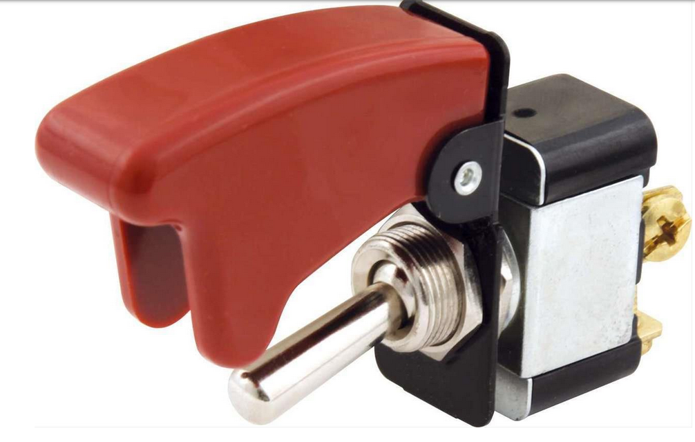
Personally, I would keep the CAD unit in place. I did so and turned it into a 2WD / 4LO truck - very beneficial for slowly backing heavy loads in tight areas. I purchased and installed a vacuum solenoid valve and a toggle switch with a lockout (switch shown below). I bought my truck new and did this conversion over 20 years ago and over 300,000 miles ago. It has never failed and the 4WD indicator lamp works as it should. John
-
Let us know your solution. This could be a future problem for my truck as well as others. John
-
Glad you got it figured out. Are you saying that there are two female connectors and two male connectors and that they will interchange? John
-
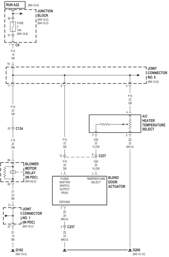
Is your part number 604018 (a Dorman part number)? From what I have read on-line, this blend door actuator motor is universal and should work on your truck. It seems that there should be a calibration procedure, but I cannot find one on-line. It might be worth a call to the manufacturer to see what they have to say. Another possibility is to find a used actuator motor from a salvage yard. John
-
Wow! I have to commend your perseverance to get as far as you have. Good description of your issue. I don't have much offer at the moment. I think you may be right in regarding a previous owner thinking there was a dash wiring problem. Electrical ground problems, back feeding problems, and short circuit problems can be some of the most challenging electrical issues to solve. I think I would put my first focus on finding what is causing the 15 amp park lighting circuit fuse to blow under certain circumstances. You find that, then maybe everything else will fall into place. Also, I would look for any evidence of other accessories (especially lighting) that may have been wired by a previous owner. Do you have a wiring diagram to work from? John
-
It will give you time to clear your mind and come up with a good diagnostic approach. Possible issues to keep in mind: intermittent fuel supply blockage, especially suction side of lift pump large amount of air in fuel system (not likely) intermittent power to lift pump faulty lift pump (pressure regulator issue) When things get difficult to diagnose for me, I change tactics and try to prove what is working CORRECTLY, not what is working INCORRECTLY - a process of elimination. This method will sometimes get the issue resolved sooner than focusing on things that one might think is wrong. John
-
Are you referring to the wiring connector to the blend door actuator that shows a three-wire connection? It looks like others have had the problem you are having. Have you confirmed that you really have a blend door motor actuator problem, or is it possible that the interposer (plastic shaft) is cracked and slipping on the old one? In that case, you can just replace with Heater Treater's steel interposer. You will have to reset the gears though. Heater Treater has a video how to get the gears timed. John
-
Give details of your bucket test. Have you ran the engine while drawing fuel from the bucket with a separate power source to the lift pump? I'm having a hard time with believing it to be a VP44 overflow valve problem. Did the FASS representative explain with detail on exactly how an VP44 overflow valve problem would adversely affect lift pump pressure? Also, if there is a restriction in the fuel supply anywhere in the lift pump circuit (especially the suction side), then unpredictable fuel pressure could be expected. What it the GPH rating on your lift pump? John
-
So, it sounds like the lift pump relay was not the issue? Symptoms remain the same? John
-
You could just disconnect the fuel pump relay to test a warm start condition. Rig up a jumper wire to hold in your hand while you start the truck - that way you can control when the lift pump runs (or doesn't run) for your test. At least, it would let you know if too high lift pump pressure is causing your long crank on a warm start. John
-
@Mopar1973Man, that would be you...., John
-
Does this mean NO slow start when the engine is cold? If so, your lift pump pressure may be too high. The OEM fuel pump setup uses PWM (pulse width modulation) to reduce supply voltage to the lift pump, thus reducing fuel pressure, while cranking. The reasoning is that high lift pump pressure during cranking can affect the position of the timing piston, thus making the engine hard to start when warm. Not everyone has experienced this, but some have. Is your relay wired directly from the battery? You could try reducing lift pump pressure to see if this helps starting a warm engine. Don't get caught up in the, "you gotta have at least 14 psi lift pump pressure", as it is not true. Take it down to 12 psi or so at idle and see if that helps. Good to hear you found the problem with the lift pump. John
-
On my truck the tee at the back of the head started to leak fuel about 15,000 miles ago (at 390,000 miles). At the time I had the transmission out while doing a clutch job and I noticed the leak. The connections were loose, so I just tightened the them from below. They have never leaked since. A leaking tee fitting (even if it's only leaking air) can cause long cranking times, but it will not affect fuel pressure after the engine is running - so, not likely to be your problem. I haven't tried accessing the tee fitting from the top of the engine. I would probably remove the valve cover and use a mirror to inspect the connections and then blindly reach around the back of the head to tighten them. John
-
The tech is probably referring to the 14 psi overflow valve in the VP44 injection pump. This pressure control valve is very reliable and I am almost certain it is not your problem. People have replaced this valve because of not understanding how the fuel system works, and then found after replacement, their symptoms didn't change. Even if the overflow valve failed (as in opening at a lower pressure), it would have little or no effect on lift pump pressure. All fuel that enters the VP44 must pass through in internal fixed displacement vane pump. This pump is regulated at 100 - 300 psi depending on engine rpm and engine load. Because the internal vane pump is fixed displacement, additional fuel cannot be forced through it regardless of lift pump pressure. Both Airdog and FASS lift pumps use a ball and spring check valve to regulate fuel pressure by recirculating any fuel that is not being used by the injectors and the VP44 cooling system. If the lift pumps are high volume pumps (which yours probably is), then a lot of fuel has to recirculate, in fact more fuel recirculates than gets used. The pressure control valves on these lift pumps are usually not of high quality and the ball and seat can take a beating, which can cause symptoms that you are experiencing. I am surprised that the Tech didn't mention this. I would be looking at two possibilities for low / erratic lift pump pressure. Check the condition of the ball, spring, and seat in the lift pump. Check for any restriction / leaks in the low pressure fuel supply. Pay special attention to the suction fuel lines from inside the fuel tank to the lift pump. Many people that have observed erratic lift pump pressure have stretched the spring in the lift pump's pressure regulating valve for a bit more tension. For some it gave desired results. John
-
From what I understand regarding engine break-in for Cummins, is to operate the engine at various engine rpm's and various engine loads for a specified number miles (not sure about the miles ), and to not use synthetic oil during the break-in period. What Cummins does not want is a steady engine rpm and a steady engine load. Not sure about the use of break-in oil. John
-
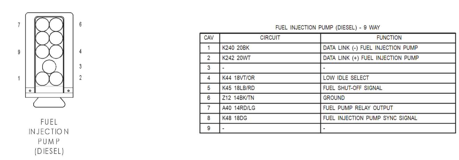
I think you would have found it. Your scanner was telling you that you had low voltage at the injection pump. I should have recommended that you check that connection as that connector is part of the battery supply voltage. You ought to hook your scanner and see if the voltage to the injection pump is now steady and higher than it was. That would help to confirm your find. John
-
A poor connection at Pin #7 would absolutely match your symptoms, as it is the 12 volt power supply from the fuel pump relay. Keep us posted - hoping you will never experience the issue again. John
-
I was using the FSM to figure out what your corroded wire operated. If I am looking at the diagram correctly, terminal #9 should be the culprit. This pin-out says #9 isn't used. Am I looking at the correct pin? Do you know the wire color? John
-
This is great news! Your perseverance has paid off. I think you have found the problem. And you did it without replacing a bunch of parts. Congratulations! Good job with repairing that connector. John
-
Had you noticed any driveline vibration or noise prior to the event? Had the driveline been removed and re-installed recently? Was the rear u-joint still in good operating condition disregarding the damage from the end yoke failure? In other words, were the end caps lubed, not dry? How do you use this truck? Does it do any sled pulling? burnouts? I only ask these questions just to cover anything that may generate shock loads to the drivetrain. Personally, I would just replace the parts needed with the OEM style end yoke. After seeing what happened with your truck, I think I will inspect the end yoke on my truck. - John


