Jump to content
Mopar1973Man.Com LLC
  • Welcome To Mopar1973Man.Com LLC

    We are a privately owned support forum for the Dodge Ram Cummins Diesels. All information is free to read for everyone. To interact or ask questions you must have a subscription plan to enable all other features beyond reading. Please go over to the Subscription Page and pick out a plan that fits you best. At any time you wish to cancel the subscription please go back over to the Subscription Page and hit the Cancel button and your subscription will be stopped. All subscriptions are auto-renewing. 

Building a he351 standalone controller


Recommended Posts

  • 2 weeks later...

Hey would you know why my EB isnt working correctly? I checked the values in the code and they are set to 900, 1000 which is right for 3cm but when i engage it it goes to 25cm just to try it i changed the values to 40, 140 and it did not make a difference? Any help would be appreciated everything else seems to be working as it should.

Link to comment
Share on other sites

  • Owner

Can you write a bit of code to show the variable for the vanes so you can see if they are actually be set right or is there another bit of code over riding your value. I sometime fight web code the same way and just plop in a more or less "print X" and look at what the software is doing. I've made coding mistakes where the set value was being over written by anothe command. 

  • Thanks 1
Link to comment
Share on other sites

When it comes to code i really dont know what im doing ive done a little research on it but that only gets me so far. The code i have is from the building a standalone controller on this fourm, but the tests i have done the turbo speed sensor is not hooked up idk if that will affect it.  All i know i test fitted the controller on the truck and the pot sensor works good and the cm^2 numerals on the lcd screen are correct to the vein position. Do you know of a video or source online that i can use to troubleshoot this ?

Link to comment
Share on other sites

i wouldn't think so but i have no idea honestly i have the "turbo reset code" and it positions the veins where they should be then when i upload the main code the veins will cycle the way they should be IE if theres over 10 psi of boost the veins will open the pot switch will work correctly with the lcd screen 25cm is opened all the way and 3 is closed maybe the code is getting thrown off since the tps isnt hooked up ill try editing that out just to see what happens.

Link to comment
Share on other sites

You need to limit the value of the variable: final_vane_position right before the CAN send function so that only valid values are sent. So that if something goes wrong while tinkering.


Insert this:

final_vane_position = constrain(final_vane_position, 40, 960); // prevent non valid position data

Just before line:

byte lo_byte = lowByte( blah blah);

Try that. You can hack up an  lcd.print(drive or whatever); to lcd.print(final_vane_position); to actually see the value.

Edited by Great work!
Spelling
Link to comment
Share on other sites

Hi Everyone,

I’m following this forum for long time and I wanted to thanks everyone for sharing their knowledge and experience, I learn a lot from you guys, so thank you very much.


Currently I’m working on refurbished Holset He300VG turbo actuator, and I’ll be glad if someone can assist me little with controlling the motor.

I’m using 12v\10A power supply.

I connected everything according the instruction.

(On holset main plug the connection are: (GND – CanL – CanH – 12v). (See pic)

I sent the calibration code: (CFFC600, extID , 8,FF FF 02 FF FF FF FF FF)

And I can see the motor rotating to one direction as it supposed to do, after that I must recycle the power.

I connected my Arduino to can bus shield and then connect it to 4 potentiometers + 2 on\off switches.

The sensor connection are:

Boost pot – A0

Drive pot – A1

Pot – A2

TPS  - A3.

“Switch” connect the GND to digital pin 7

“EBswitch” connect the GND to digital pin 8 (just to make sure pin 9 is not used by the SPI (See pic)

I upload the A_HE351Mainfreq_TPS 1.11 sketch (not the 1.12), the LCD has some problems so I comment his lines.

My can bus shield use pin 10 to communicate with the Arduino.

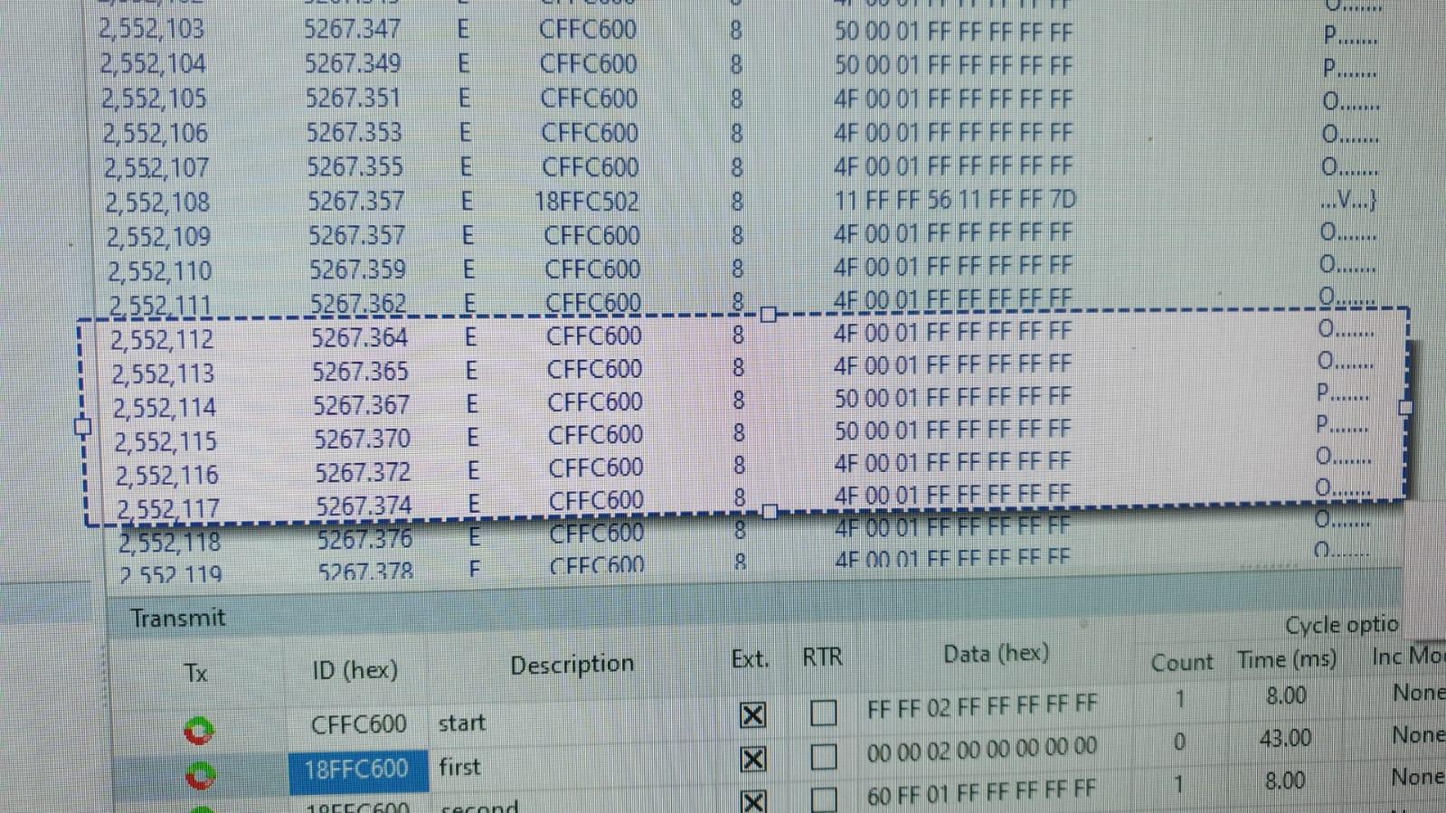
Next I checked the can bus messages using Ixxat (usb to can). (See pic)

And I can see the numbering changing when I move the pots and switches.

The problem is that the motor is not rotating left or right.

I saw on the sketch :

//const int RPMpin = 2;
//const int RPMpinInterrupt = 1;
//int RPM = 0;
//
//volatile int RPMcounts;
//const byte CrankPulsePerRev = 2; //How many crank pulses you get.. if your RPM readings are off, check this.. 


I connected everything in my lab so I don’t have RPM reading, can the actuator work properly without these readings?

Maybe you have an idea what else can I do?

I upload some pictures, may be it can help...

can bus on scope.jpeg

HE300VG connector.png

sensor ans switchs connected to the arduino.jpeg

sensors to arduino scheme.jpeg

the full system connections.jpeg

Link to comment
Share on other sites

Is rpm sensor 2 or 3 wire type?

Try toggling LED on uno and connect to scope for debugging. Toggle LED  in the CAN send funtion to test. 

Try short cutting the code by sending a pot reading to CAN.

Example final_vane_position = (analog.read(A0) / 2); where your pot connects. 

Link to comment
Share on other sites

Great Work!
thanks for your reply.

I didn't connect the rpm sensor, I saw in the code it was in comment. can the stand alone tester work without the rpm input?

Is there a way to simulate this sensor, lets say sample the throttle value that is corelate to the rpm value and insert it to pin 2 (as written in the code)?


5 hours ago, Great work! said:

Try toggling LED on uno and connect to scope for debugging. Toggle LED  in the CAN send funtion to test. 

I'm not sure what did you mean by that, you want me to send a canbus a command in order to toggle a led? I can try it, but I believe my communication is working well after I sent the calibration command : 0x0ff0600,extID,8, 0x00,0x00,0x02,0xff,0xff,0xff,0xff,0xff - and the motor rotate to one direction.


5 hours ago, Great work! said:

Try short cutting the code by sending a pot reading to CAN.

when I rotate the pot I can see the number changing. so I know the can bus its ok.


5 hours ago, Great work! said:

Example final_vane_position = (analog.read(A0) / 2); where your pot connects. 

so, instead of sampling the outside potentiometer (pot), you suggest to sample the boost pot(A0) divide by 2 and send it to the final_vane_position?

void set_turbo_position() {
    //final_vane_position = vane_position; //original code
    final_vane_position = (analogRead(A0)/2);

what we want to accomplish by that? I tried it without any change....

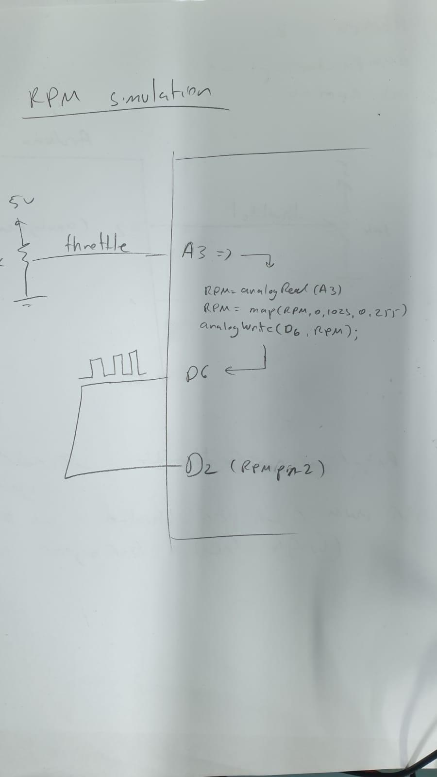
i dont have the max9924 chip so i tried to simulate the rpm by sampling the throttle pin(A3) and send it as PWM to pin 2 (RPMpin2)  - what do you think about that? can it work?

1522757187_samplingA3forsimulatiingRPM.jpeg.737d7d60dc1901c8328fcb590177fc9e.jpeg

Link to comment
Share on other sites

The pot to set vanes manually will override the RPM calc section of the code, but hte pot I used was a push pull pot to enable or disable on another pin, I dont remember which anymore.  


The most common thing I seen was the wrong pin being used for the can control due to issues with board differences / spec and other conflicts on the can pin.   


You might try a simplier versioin of the code to only send can position based on pot position.   however if the turbo acts like it wants to find the limits when the calibrate command is sent, but does not want to do anyhting when the normal code is running then it suggests that the can communication is working, but something else isn't.   


another thing is if the code does not fire off a message every ~50-200 ms then the turbo should "reset" or jump back to a position over and over.   I dont remember how long though,  if I remmeber right I think it jumps to wide open.


Edited by Me78569
Link to comment
Share on other sites

28 minutes ago, Me78569 said:

The pot to set vanes manually will override the RPM calc section of the code, but hte pot I used was a push pull pot to enable or disable on another pin, I dont remember which anymore. 

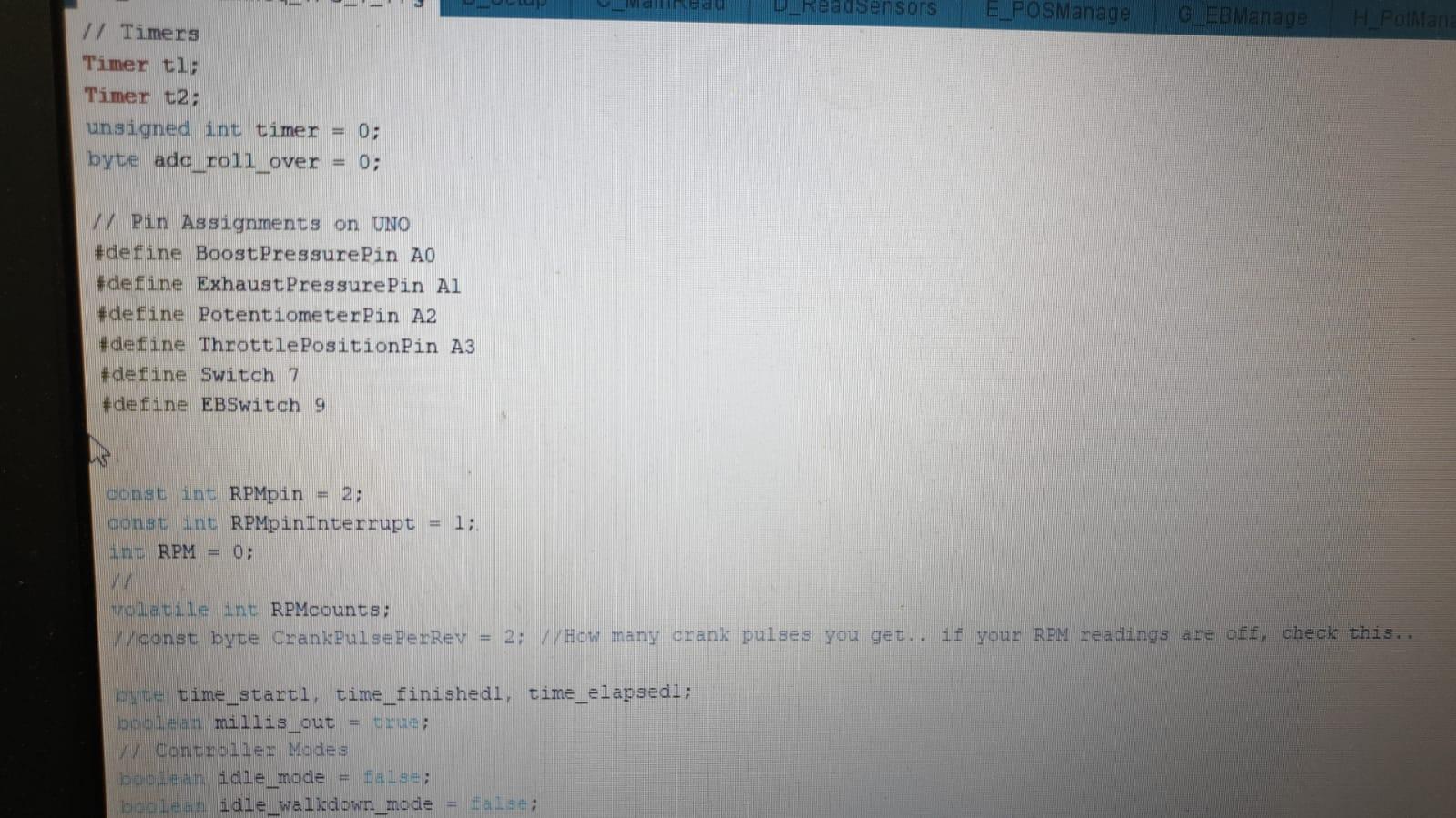
thanks for your reply, according the code you use only pins A0, A1,A2,A3,7,9,2,1 so maybe you used the push pull pot on another code.

1052711049_sketchvariables.jpeg.614dfbf6ae86159ca1e60a0e4c5aaab2.jpeg


34 minutes ago, Me78569 said:

another thing is if the code does not fire off a message every ~50-200 ms then the turbo should "reset" or jump back to a position over and over.   I dont remember how long though,  if I remmeber right I think it jumps to wide open.

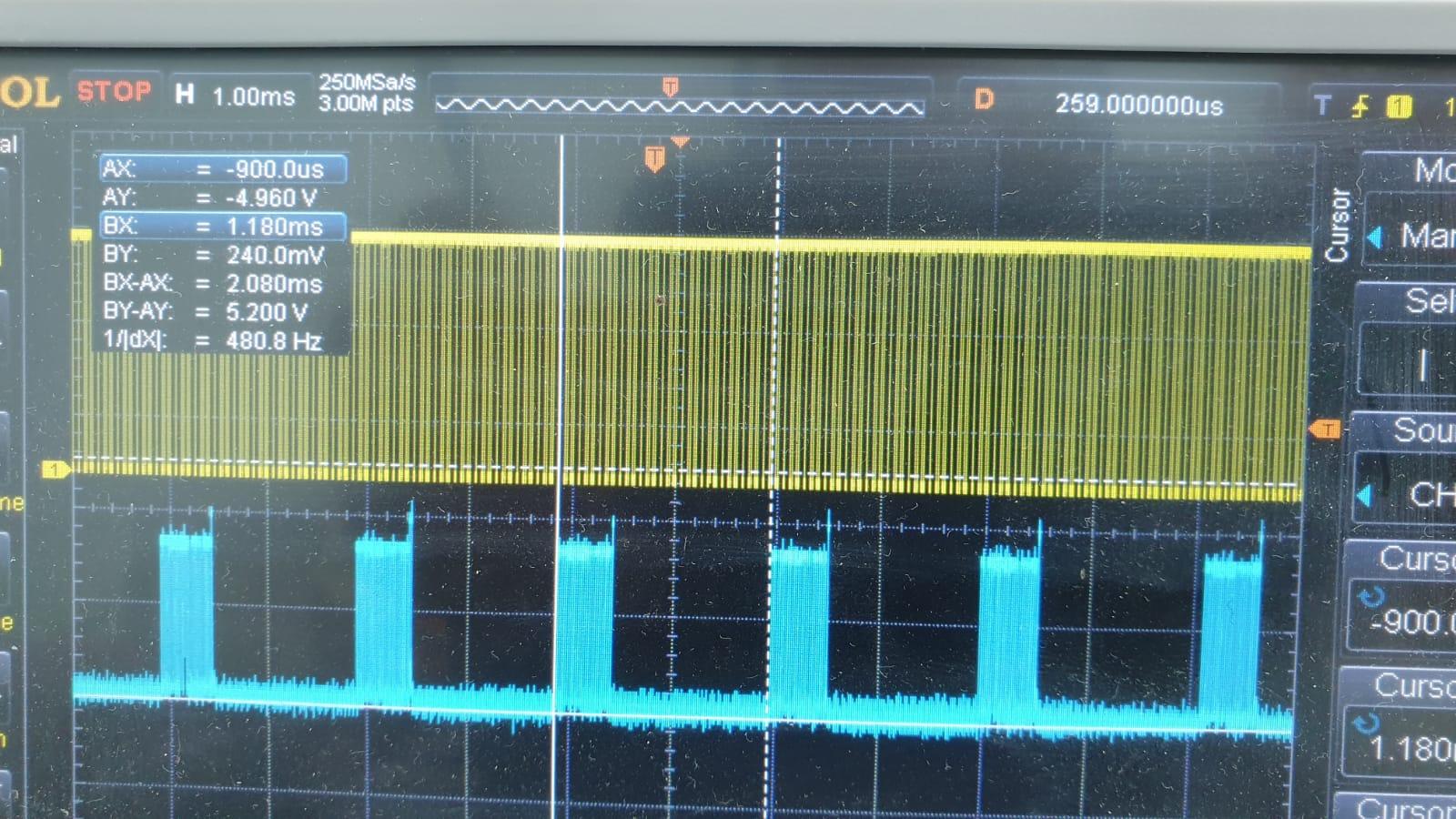
you right about that, i remember I read somewhere that can messages should be every 10ms, i capture my communication with my scope and the can messages are every 2.080ms so i believe its not the problem.

1749030972_canmessagefreq.jpeg.f54f0f31bff558dc23de6ce55be48dad.jpeg

 can you or someone else can upload simple code for moving the motor with only one pot? in the past i took the calibration code and changed it to read the pot and send the command to the vans, but with no success...


Link to comment
Share on other sites

Hi,

It's a good question!!

when I'm sending the calibration command my motor rotate only to one direction, I believe its happen because he can't find the limits.. maybe he goes to "shutdown" state and 
that's why I need to recycle the power after every calibration command....

So what you actually saying is only after the calibration success (moving on both side and hitting the limits) I can effect the motors movement with the whole circuit..

its a good way of thinking.... thank you very much, I must try it !

Link to comment
Share on other sites

×
×
  • Create New...