Jump to content
  • Welcome To Mopar1973Man.Com LLC

    We are a privately owned support forum for the Dodge Ram Cummins Diesels. All information is free to read for everyone. To interact or ask questions you must have a subscription plan to enable all other features beyond reading. Please go over to the Subscription Page and pick out a plan that fits you best. At any time you wish to cancel the subscription please go back over to the Subscription Page and hit the Cancel button and your subscription will be stopped. All subscriptions are auto-renewing. 

ANOTHER fuel question


Recommended Posts

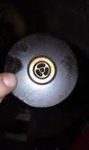
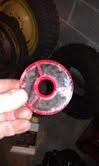
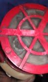
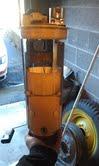
so this is what i knowthe supply line from the tank comes up around the area of the fuel filter canister, it runs through an L bracket clamp down to the fuel heater prefilter, then out of the pre filter into the from of the LP through a molded hose and 90 degree brass fitting. from there it goes of the the LP straight up to the bleeder screw on top of the fuel canister.i just want to know FOR SURE that of im running new line from my tank to the engine it would connect from the tank to the pre filter and then i would leave the rest as stock. is that correct?also is there any actual replaceable filter in the pre filter assembly?thanks in advanceNICK

Link to comment
Share on other sites

  • Owner

Hopefully ISX shows up he should know a bout more about the fuel system routing. As for what I know I think your right where it passes the pre-filter and then lift pump and up to the main filter... But don't quote me on this...Another one that could answer this is Relentless70 he's also a 1st gen owner but I've not seen him in a while... :rolleyes:

Link to comment
Share on other sites

  • Staff

I have a 92.There is no prefilter unless you add one. It's a very good idea and to place it before the lift pump is tops. On mine it goes thru a shut off valve,to the pre filter, then liftpump, then thru the factory filter, then to the I/P. On my 92 the fuel heater is on top of the fuel filter sort of like a doughnut sitting stacked ontop. You can remove the fuel heater by removing the threaded nipple that the filter screws onto. If I remember right, it is a star type wrench with a slot across if you would rather use a large screw driver instead of the star tip.Oh yeah.... it's important every once in awhile to remove the fuel heater, REMEMBERING WHICH WAY IS THE TOP, and soak it in some diesel and blow it out. Be surprised how much junk gets in there. I think mine was dirty from never having a prefilter for a 100,000 miles.I placed the prefilter under the hood inside the drivers side fender. I had to make a bracket to hold it out of the way of everything. I also placed a shut off valve in the line for changing both filters to prevent fuel drain back to the tank. Very handy. If you want a first class job, get the filter with it's own priming pump. My racor works like a charm. Much better than the little lever on the fuel pump.

Link to comment
Share on other sites

You are correct. Tank goes to the prefilter. All you would do would be run the new hose to the steel line coming off of that prefilter. The prefilter screen is replaceable but you normally just take it out and clean it since it's steel mesh. http://www.genosgarage.com/prodinfo.asp?number=3845400S The return line goes to the other steel line coming off the banjo bolt on the front of the P7100, nothing taps off that line as that is the only return. The injectors return to the top of the fuel filter.

Link to comment
Share on other sites

ISX- my plan was to go from the tank to the pre filter and use a barb fitting to take my supply line right into the prefilter. I think.i.would have to do this as my new supply is 1/2 inch.As for the return, i was going to remove the hose clamp by the fuel filter, slide off the rubber hose and replace with the new rubber hose then run it to the tank. So the fitting between the head and IP would not be messed with as wrll as the steel line.Sorry for grammer errors ahead of time on my phone lol

Link to comment
Share on other sites

That will work. As long as it gets from A to B then it will work :thumb1: Return line sounds good too. If that stock steel line is too small for the 1/2" hose you might get a small barb to 1/2" barb adapter and cut off 6" of that old rubber hose so you can go from the steel line to the barb then you will be able to hook the 1/2" on the other side of the barb. Otherwise you are dealing with a banjo fitting. It isn't just any banjo bolt either, it has a pressure relief in the bolt so it pretty well needs to be there unless you come up with some fancy way to regulate 35psi. This is probably way more than you want to know but just in case you get really carried away lol.

Link to comment
Share on other sites

The prefilter with the heater is not required for our trucks. I have a '98 12v in my driveway that has had the prefilter by passed for the last five years. Being in northern Minnesota there has not even been one time it was gelled.

Link to comment
Share on other sites

Yeah I was going to say you could dump the 3" little rubber hose going from the prefilter to the lift pump but I do remember mine always has some crap in it so it might be better. No problem, let me know if you need pics as I got pics of all this stuff..

Link to comment
Share on other sites

I'll go take mine off and check. Think it's 1/4" NPT but I'll make sure.

--- Update to the previous post...

Alright I got it out. It is actually 3/8" NPT.

Here's some pics just in case you wondered what was there.

Posted Image

Posted Image

Posted Image

Link to comment
Share on other sites

Hi ISX, I was ready to do pretty much the same supply Ln mod.. But I chased my tail here in Chattanooga Tn trying to find an old LP or a new one to get those fittings. I REALy did'nt want to take mine off unless absolutly had to. Should have aksed first.. I first wanted to put the 1/2 ln directly to the LP 90 elbow. (this will accomidate a 1/2 Ln well with a clamp, and leave the pre Heat alone. Changed mind like prefilter, not the preheat element. Now that new supply and return Lns run, AND the bed is still off, reconsidering. Your feed back on this. 1st I have a Vulcan draw straw for my 98 3500 with 1/2 and 3/8 push ports. and the 1/2 rubber Ln not installed yet. My idea was to upgrade larger Ln now and later to a electric LP. 2nd to relieve fuel supply ln of restriction at OEM sending unit and near engine quick conn steel Ln that rus to LP pre Htr. I'm thinking(see the smoke) just run 1/2 Ln from NEW draw straw in sending unit to LP pre filter on a 3/8 npt/ push barb or some similar fitting. To do this I DO have to take LP off. Aside from enlarging the finder cut out is there a better way to get to the LP? what do think of all this jabber?? thank you for the pics and consulting, Dave

Link to comment
Share on other sites

The 12 valves are fine with the stock 3/8 line, going bigger is fine but not needed imo. We run higher lift pump pressures than the 24v's so it makes up for smaller size. No matter what you do it sounds like it will work, all it does pre-lift pump is suck fuel in so even the barb and a hose clamp would work fine. Just make sure to get fuel line hose or the diesel might eat at it over time. Diesel doesn't eat at things like gas but it is still a chemical. It sounds like you are intimidated by taking the lift pump off. I will make a video of putting it back on (since I took it off last night) to help you. Getting it off is a lot easier than putting it back on, but its mainly just this one bolt on the lift pump that can ruin your life. It is a 30-60 min job.

Link to comment
Share on other sites

It sounds like you are intimidated by taking the lift pump off. I will make a video of putting it back on (since I took it off last night) to help you. Getting it off is a lot easier than putting it back on, but its mainly just this one bolt on the lift pump that can ruin your life. It is a 30-60 min job.

Link to comment
Share on other sites

I didn't want to put it back on since I need some seals so I tried to do a walkthrough of it. Hope this helps. Oh and you do the center bolt on the lift pump first so you can shove it in easier, if you do the one on the side first it is a complete PITA. Forgot about that. I did an incredibly detailed 10 min movie first but it was so detailed and long I made another lol.

  • Like 1
Link to comment
Share on other sites

ISX thank you for the video. I know this will help alot of folks. Evaluating the LP take off and taking the preheater out, I found a split priner boot. Truck has 165K I think I'll replace it. Have you installed aftermarket units or stayed with carter brand? Where to buy?On finding BTDC discussion, since I have to do KDP can I align timming marks on timming gear and cam gear then put harmonic balancer on and mark it??? (See the smoke again) Your shop heated, and are slippers optional? I have to lite the blower and suck fuems. At least I'm inside...

Link to comment
Share on other sites

ISX thank you for the video. I know this will help alot of folks. Evaluating the LP take off and taking the preheater out, I found a split priner boot. Truck has 165K I think I'll replace it. Have you installed aftermarket units or stayed with carter brand? Where to buy? On finding BTDC discussion, since I have to do KDP can I align timming marks on timming gear and cam gear then put harmonic balancer on and mark it??? (See the smoke again) Your shop heated, and are slippers optional? I have to lite the blower and suck fuems. At least I'm inside...

The carter is fine. It is very reliable and you just can't beat it. The only place I found one just searching is here http://www.puredieselpower.com/catalog/19941998-dodge-59l-valve-cummins-mechanical-lift-pump-p-193.html I would ask around on some bigger forums or ask in the vendors section of this site as I am not sure of puredieselpowers reputation, the last guy I sent over there for CAD parts got all wrong stuff.. You could do that method for finding TDC but it won't be as accurate. The valve drop method with the dial indicator is pretty well dead nuts. You want it dead nuts when dealing with timing. If you just want TDC for valves, don't even bother trying to make it complicated. Rotate the engine and watch #1 or #6 and wait until one of the valves open (depending on which way you are rotating the engine), whenever the exhaust valve opens, keep rotating and it will start to close. Before the exhaust valve is fully closed, the intake will begin to open. The instant you see the intake valve move, stop. Mark the damper and that is a crude TDC mark for faster valve setting than having to watch the valves. For timing it needs to be really accurate. As easy as the valve drop method is there is really no reason to not be that accurate. When setting the valves, TDC does not have to be accurate at all. Watching for valve overlap is way overkill on accuracy but it is very quick and placing a mark on the damper will make it even quicker. You don't want to know how far off you can be from TDC and still be able to set the valves..:stuned: We had a torpedo heater and brother must have taken it so now I have to light the wood stove. I didn't feel like putting shoes on lol.
Link to comment
Share on other sites

Thanks again ISX I'll keep that in mind. I will do the drop valve to be dead on with the injector timming. I was considering the spill port method though. Anyway. New LP kit from Genos on the way and install on Friday. Dave

The spill port method is how you find the point of initial injection of the P7100. It is the point where all timing is derived. It goes hand in hand with the absolute TDC of the engine.. When you find TDC of the engine and the point of initial injection of the pump, you can loosen the pump nut, rotate the engine backwards to the desired degree (you can use calipers to find the chord of the circle (damper) and make another mark which would be the degree you wanted). This means you would have a TDC mark and a say 15* mark. You unlock the pump on initial injection, rotate engine backwards to the 15* mark, tighten the nut back up and you are at exactly 15* BTDC. Just make sure if you do that, that you rotate the engine backwards to hit the TDC mark, otherwise there will be backlash in it. That chart that everyone uses is actually derived from the spill port method as the spill port method is the single most accurate thing you can do. What they are doing for that chart is doing the same thing to get to 15*, then putting a dial indicator on top of the plunger and then rotating the engine back to TDC and seeing how much lift there was in the plungers movement. It would be interesting to get dead nuts with the TDC and do the spill port thing and see how far off the chart is lol. I would expect it to be right on but I would like to know for sure.
Link to comment
Share on other sites

×
×
  • Create New...