Jump to content
Posted

Hi all,

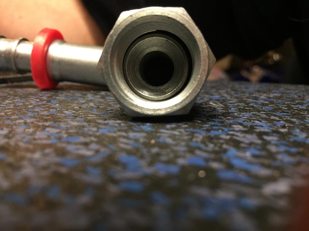
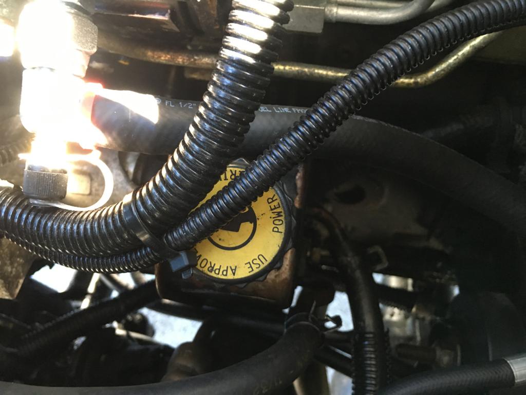
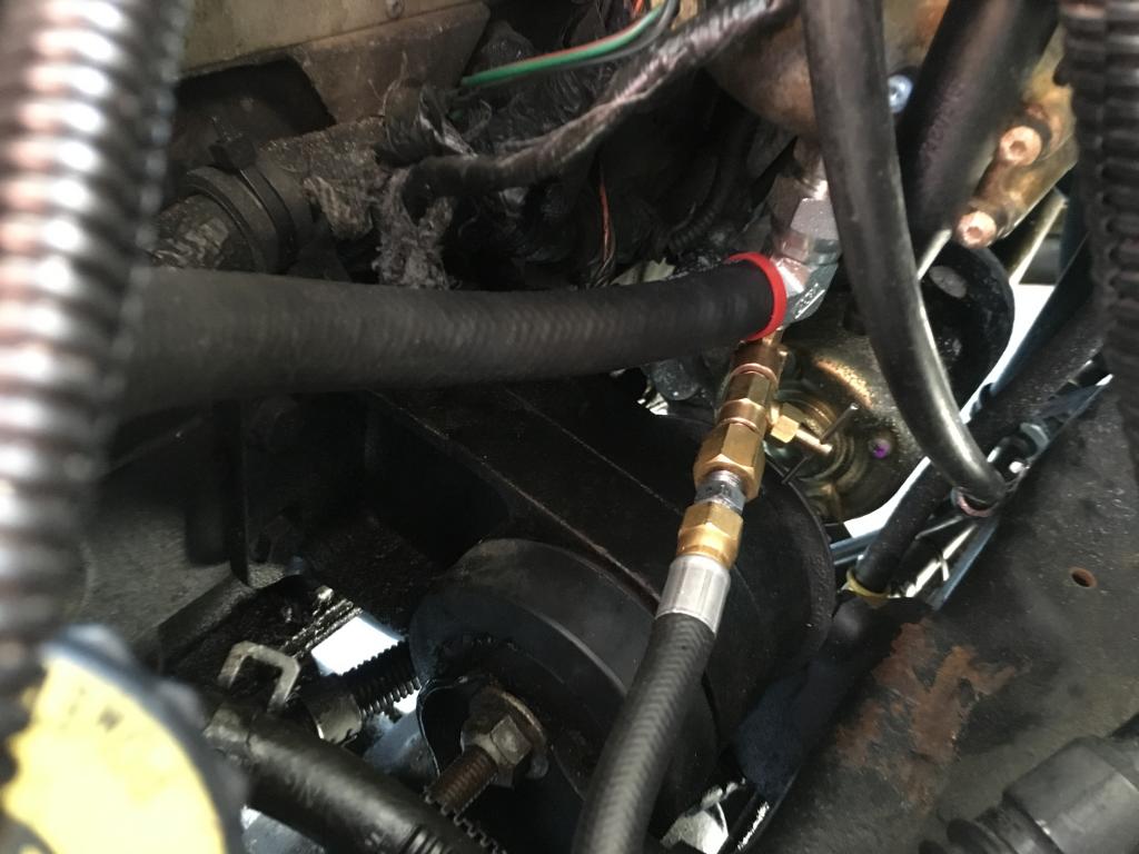
So shortly after getting my Fuel Boss lift pump and big line kit installed a few months ago I noticed that I have a 1-2 psi needle bounce in my autometer mechanical fuel pressure gauge. I am using a snubber from Geno's and my pressure tap is located on the filter canister outlet. As you can see here.

IMG_0732.jpg

IMG_0727.jpg

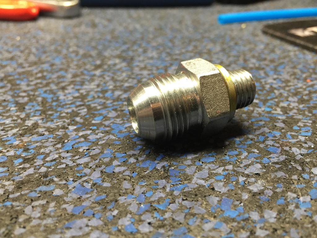
The items are from left to right, Female JIC end of Vulcan Universal Fuel line(brass), Male JIC to NPT adapter(silver), Geno's snubber(brass), Street 90 from Ace(brass). This setup comes out of the tapped 90 that attaches to the bottom of the fuel filter canister. 


Anyway, I've dealt with the needle bounce for this long, but I always regretted not installing a needle valve so that I could turn the gauge supply off in an emergency. The more I thought about it, I realized that adding a needle valve would probably help with my needle bounce and make my gauge last longer. So I got one from Vulcan. My question is, should I used the snubber and the needle valve? or just the needle valve? The only thing that concerns me about using both is that assembly is getting long and heavy where it comes out of that tapped 90. Also, does it matter what order I put the items in? I am also looking for recommendations on thread sealant for the NPT threads. I have used this 

IMG_0736.jpg

and this

IMG_0737.jpg

in the past and both seem to be ok. The 545 is the purple liquid stuff and I always feel like I need to let it sit overnight before running fuel through it. The 567 is more like regular pipe dope. I always figured the purple liquid stuff was safer for a post filter application than pipe dope just incase some got to the injectors. But I was told when I did my Fuel Boss install that regular white(PTFE or whatever its called) pipe dope was fine for that. I would like to know what you all think and normally use. 

Thanks in advance!

Edited by leathermaneod

  • Replies 109
  • Views 14.8k
  • Created
  • Last Reply

Top Posters In This Topic

Most Popular Posts

  • I use the yellow teflon tape typically.   Little late to the party, but  

  • leathermaneod
    leathermaneod

    Thanks for the call Mike! I really really appreciate your time and all your help. Plus its great to chat with a person who can teach me a think or two(or 100 lol) about these trucks!

  • leathermaneod
    leathermaneod

    Just want to update this I case anyone is following. When I re drilled and tapped my manifold for moving my pyrometer, I checked up on the fuel leaks again. VP end was dry but the Fuel Filter housing

Posted Images

Featured Replies

  • Author

Yeah that's what I was thinking too, as far as the mark. And thanks I love crocs haha

Duuuude they're so comfy! My wife hates that I wear them so I make a point to wear them even more! :cool::lmao:

  • Author

:lol3: I know right?? I would live in them during the summer if my wife didn't hate them so much. They are my house and boat shoes mostly. 

If you already havent, I'd call and send those pictures to Vulcan and alert them that they must have received a bad lot of those fittings because you couldnt do that with a wrench.  They're steel and if you could smash the surface like that then you would be rolling the edges of everything else too.  And no, they're not a one time fitting either.


JIC and AN are the same thing except that AN fittings are aluminum, and usually come in pretty red and blue colors.  "AN" standing for "Army/Navy" and "JIC" for "Joint Industry Council".  These fittings were designed for industrial use and can take thousands of PSI.  The only issue I have with them is even though they're all following the standard 37* flare, there's many manufactures and hopefully they all match up perfectly with one another.


Clearly though the ones you have dont have mating surfaces.

  • Author

I actually just called Eric at Vulcan but got no answer so I'm waiting for him to call back. I will post when I have answers. Thanks everyone for your input!

  • Author

well I talked to Eric a few times yesterday and emailed him this pictures. Before seeing the pictures he said he wasn't too sure what else he could do for me and offered me a refund. I told him I really need the parts to work and asked if he would look at the pics and he said of course. So I sent them over and he called back later in the day. He said they don't look quite right. But he did say that because of the tolerance in the angle you may see that mark. He said he will have his guys inspect some new fitting and make sure they are un damaged and send me another set. He said he goes through hundreds of fittings per week and so he didn't think it's a bad lot because he didn't get any other negative feedback. He did say I should try making the hose a little longer to try and put less tension on the fittings. He also said to be sure I lubricant the threads before installing. So sometime in the next week I'll be giving it another go.

  • Author

The threads of the JIC fittings. And with wd40 or diesel or something like that. Just to keep them from binding. 

I'm not sure I'd lubricate them either.  They're the same material and there's no reason for binding or corrosion.  The most common procedure for tightening up JIC is to get them hand tight and then turn them to the specified number or "flats" which will be determined by the size of the fitting.  For -8 I think its something like hand tight and then one full turn with a wrench.  You can look it up if you want but nonetheless, if the mating surfaces are matched then it wont matter how tight you get them.

  • Author

Interesting. Idk that's just what he said to do. He also said that there is some level of tolerance in the angle of the mating surfaces. For example he said they could be 35° rather than 37°. I believe he also said the torque is 35ft lbs for these. Oh and I forgot to mention before, I did ask about a brass version. He said he has never seen one from any of the manufacturers of these fittings, and he believes it's is something to do with the manufacturing process that makes brass not a good material for the 90°s and 45°s. He did say the the plating could possibly be the issues as well. One other I forgot about that he said might be possible, is that the swivel nut could be crimped on badly and so causing an issue.

Edited by leathermaneod

Yea adding diesel or WD to the mating surface seems unnecessary but I'm sure he wouldn't of mentioned it if it didn't work. The swivel nut is what I was pointing out to you in an earlier part of this thread as being bad on mine. Like was mentioned before though, it's hard to locate the actual leak on these fitting for multiple reasons.  

Ahh ok, that makes more sense. Still doesn't seem like it'd even be necessary though. Did you try it?

  • Author

So I just had an idea and I wanted to get some feedback on it ahead of time in case I still can't get things to work when I get these new fittings from Eric. What if I were to go back to banjo bolts at the filter housing and VP. I could get the hi flow banjos and 3/8 pushlok fittings for them. The one at the vp end could be tapped for my test port, and I could use a pushlok pressure access t somewhere between the vp and filter, kinda like how Mike has his I believe. What are your thoughts on this? Would I be loosing a lot of flow with the hi flow banjos? Will it hurt anything? What would you guys do?

For you to have a point contact like the pictures, One fitting is JIC (37 degree) and an SAE fitting (45 degree)  it is pretty easy to measure the angle on the male part of the fitting.   The female gets a bit trickier, but you can do it. 


Measure your male.  If it is 37 degree, paint some dychem on (black magic marker will work in this case) both mating faces.  Lightly assemble the fitting.  twist the male relative to the female under a bit of hand pressure.   If they are the same angle (or close) they will show a nice full surface fit.  If they do not (only make a ring like you see) they are not the same angle.  


Now it looks like the tolerance for both parts is +/- 2 degrees.  So there can be a 4 degree difference, and this is where tightening brings the flared tubing into proper contact with the male part.  So this is where tightening torque can become an issue. 


One big mistake my techs make, while tightening the first time, they do not hold the flared tube properly on center. (they let the assembly push the fitting.  If they don't catch it, they will tighten it and it will make a lump.  I don't see a lump in your picture.)


The parker number series for female SAE (45 degree) swivel elbows is 37982   The parker number for female JIC (37 degree) swivel elbow is 33982.  Vulcan could be easily supplied with the wrong fittings and never know it. 


Good luck!  I know you are frustrated.


Hag


  • Author

Thank you very much for that detailed explanation! So in your opinion it looks like I have one 37° and one 45°? What is the best way to measure those? Just a regular protractor? How do you measure the inside?

  On 4/14/2016 at 3:35 PM, Haggar said:

For you to have a point contact like the pictures, One fitting is JIC (37 degree) and an SAE fitting (45 degree)  it is pretty easy to measure the angle on the male part of the fitting.   The female gets a bit trickier, but you can do it. 


Measure your male.  If it is 37 degree, paint some dychem on (black magic marker will work in this case) both mating faces.  Lightly assemble the fitting.  twist the male relative to the female under a bit of hand pressure.   If they are the same angle (or close) they will show a nice full surface fit.  If they do not (only make a ring like you see) they are not the same angle.  


Now it looks like the tolerance for both parts is +/- 2 degrees.  So there can be a 4 degree difference, and this is where tightening brings the flared tubing into proper contact with the male part.  So this is where tightening torque can become an issue. 


One big mistake my techs make, while tightening the first time, they do not hold the flared tube properly on center. (they let the assembly push the fitting.  If they don't catch it, they will tighten it and it will make a lump.  I don't see a lump in your picture.)


The parker number series for female SAE (45 degree) swivel elbows is 37982   The parker number for female JIC (37 degree) swivel elbow is 33982.  Vulcan could be easily supplied with the wrong fittings and never know it. 


Good luck!  I know you are frustrated.


Hag


Just noticed you have an Autometer pyro, how does your needle act at key off?

If I were to plumb in a different setup then what I got now (which I'm going to do eventually) I'd do something like this...


Push lock T -> Needle Valve -> Schrader T -> fuel pressure gauge

                                                                     -> test gauge setup/plug


Obviously you'd have to run something different from the bottom of the fuel filter as far as connector, same goes for the connection to the VP but you'd be able to get rid of the tapped 90s on both ends.

  • Author

That's a great idea! I could go down to 3/8 hose then and just use the normal 90°s at each end. Who knows if they would seal up right lol The only downside I can see to that setup is, that you end up with a big hunk of fittings just hanging out in the middle of your hose...

I wouldn't use a 90 going into the VP. I'd go with THIS (which I will swap too when doing the above swap) because it seems like it should keep your hose a little further away from the power steering cap plus it's at less of an angle so less resistance.


As far as the hose, if your running 1/2in it should hold up fine. If you were worried about it putting to much strain on the hose or sagging/moving just zip tie it down. I wouldn't drop down to 3/8 just to run this setup though. Last time I talked to Eric we were talking about have a dual ported pushlock T like I linked in my last post. That way it'd serve the same purpose but wouldn't change hose size or anything at any point.