Jump to content

Welcome To Mopar1973Man.Com LLC

We are privately owned, with access to a professional Diesel Mechanic, who can provide additional support for Dodge Ram Cummins Diesel vehicles. Many detailed information is FREE and available to read. However, in order to interact directly with our Diesel Mechanic, Michael, by phone, via zoom, or as the web-based option, Subscription Plans are offered that will enable these and other features.  Go to the Subscription Page and Select a desired plan. At any time you wish to cancel the Subscription, click Subscription Page, select the 'Cancel' button, and it will be canceled. For your convenience, all subscriptions are on auto-renewal.

Posted

I think I've got some electrical issues. My main problem is the apps. It probably needs to be replaced..but I'm trying to properly diagnose it, or if it's something bigger. 


Back story. The truck at all speeds has what I think is "dead pedal". 47re. When I'm taking off, the truck seems to go, then cut, then go..like it's not certain where the pedal is, even though I haven't moved my foot. 


The biggest problem for me is highway driving. I can't maintain speed with cruise control. If I reset the apps by unplug, key on reset, it'll work for a while, then fall off. If I set cruise control, at say, 65mph..rather than keeping a steady engine load of say, 20%, to maintain 65 on flat road..it will shoot you to 30% for a second, then drop to 0, then jump up to 25, then zero, etc..it's like it can't properly use or calculate what the appropriate engine load needs to be. 


I've tried cleaning grounds: pcm strap, passenger body, I've deleted and hard wired passenger battery ground disconnect, I've installed a bd noise isolator, mounted to that clean passenger side body ground. 


So ohm testing. I'm no electrician, but here's what I've found. I have a digital mm, on screen it sets m infinity symbol..I guess that is milliohms? (Is that even a thing)..when the truck is off, putting neg on pass battery neg, pos to alternator case, I get 0. However, on the body grounds, firewall pcm strap, and body ground with bd iso, I get 0.03. 


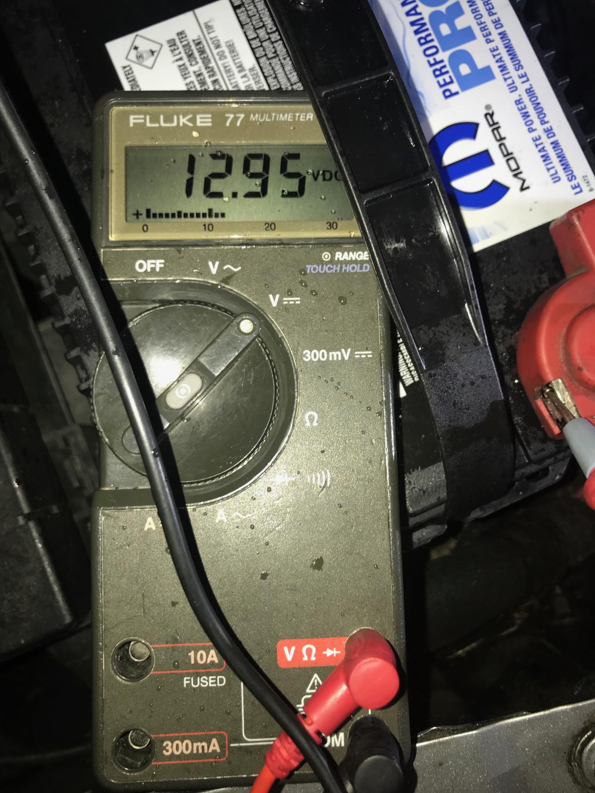
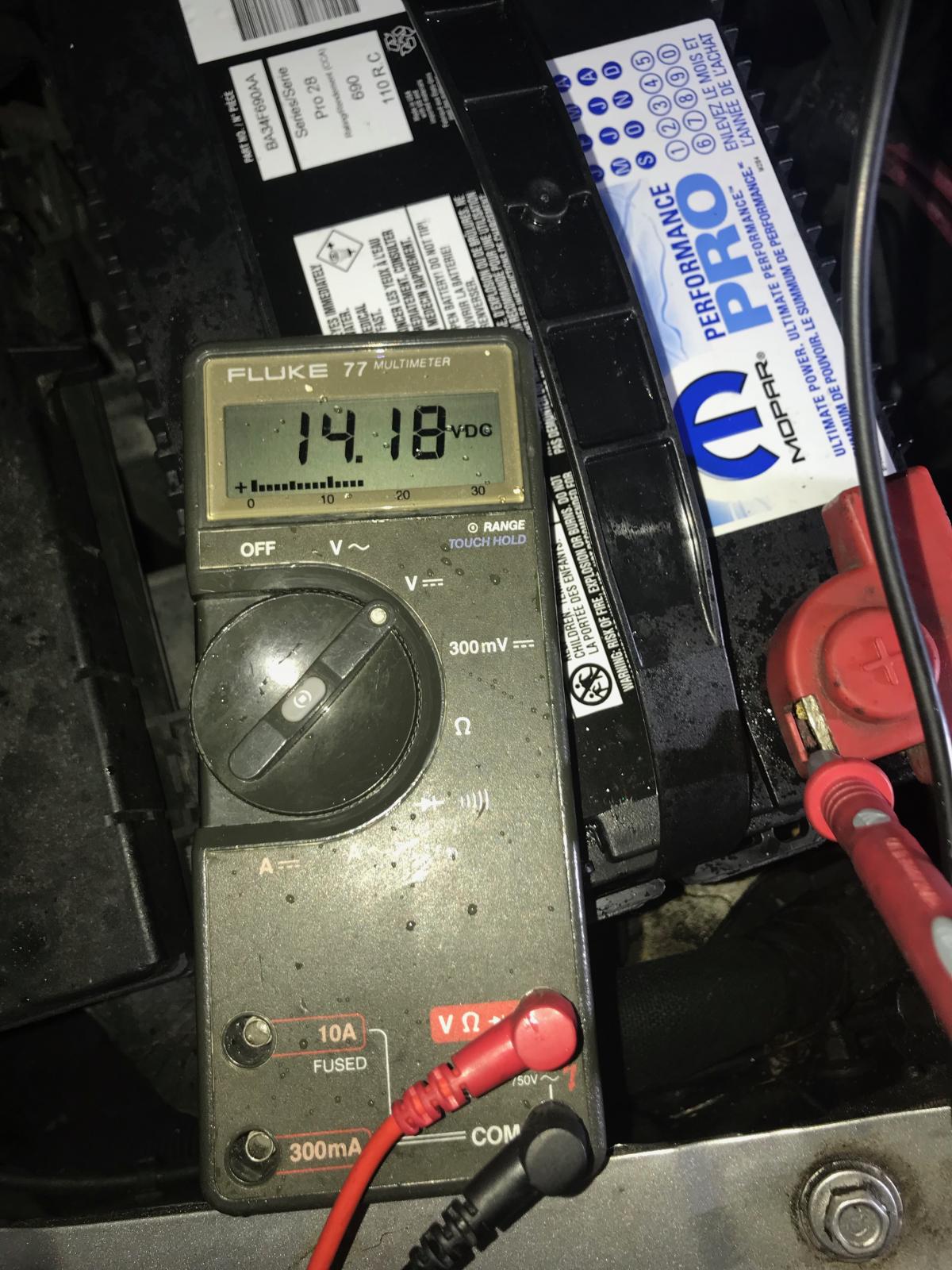
With the truck running..alternator case / block, it's still 0. However, body grounds and firewall ground to pcm go up to..0.16. Is this within spec, and what could cause such huge increase?


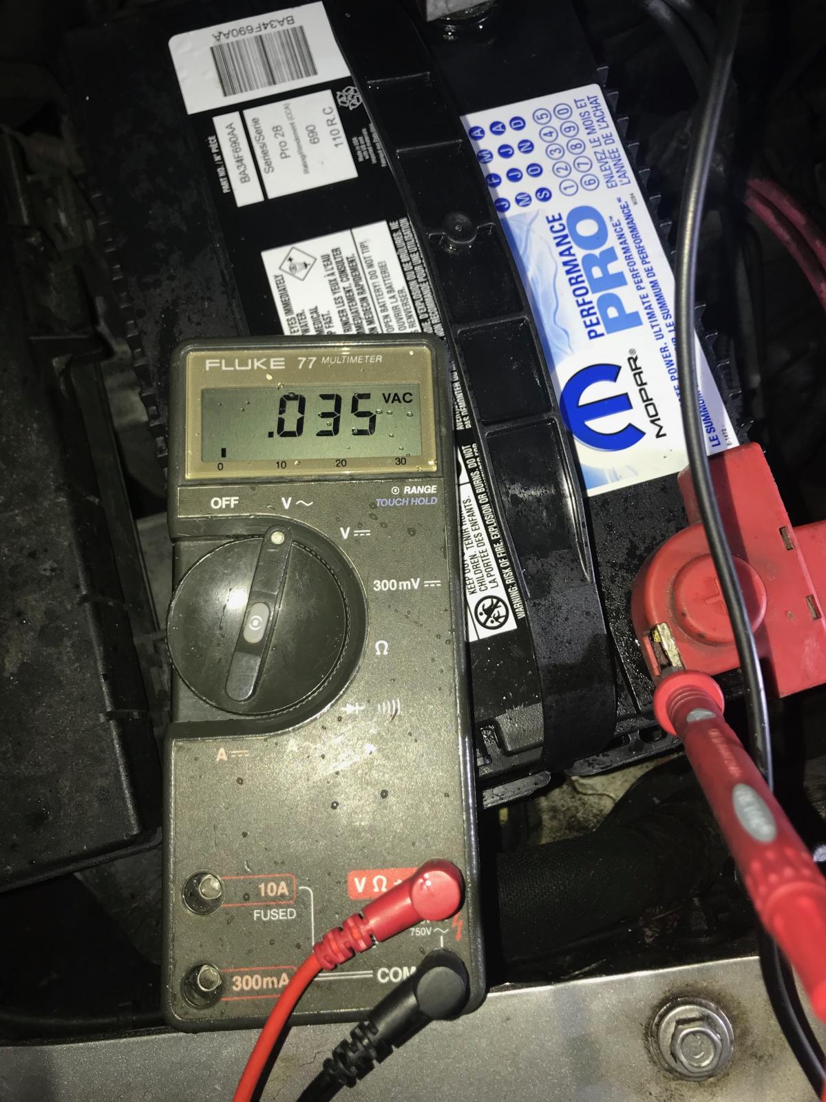
I have a nation's alternator, because my old one was leaking ac noise..this one however, is not. My black / tan is routed out to radiator, then around to battery. It is not wrapped in tin foil. 


I had my battery terminals replaced with military terms. (I asked for new cables too, but they retermed old..). Anyway, I've noticed some battery spill on both batteries. Passenger side new pos term has a tiny bit of corrosion, but the term itself has turned dark gray. I never had any corrosion on my old terms..and I did notice my voltage, temporarily in the morning, was higher than usual..not grid heater fluctuating, but constant. I felt the battery cables when I got home that day, they weren't warm at that time..but I feel like I've got some intermittent electrical issues I don't know how to identify properly. 


Oh, and my radio stopped working completely. It started off occasionally, then it would randomly turn back on once n a while..now it never turns on. It has power, lights, hitting volume turns clock on for a few seconds, then turns off again.


My blinkers, both sides, randomly stick on. I think that has to do with gauge installation tho..probably unrelated.


Jesus, sorry for long winded post..I hope someone can skim and help lol. 

Batteries are from 2015..had them load tested at an interstate battery store..said they were fine

IMG_20181031_223016.jpg

IMG_20181031_222949.jpg

  • Replies 85
  • Views 10.8k
  • Created
  • Last Reply

Top Posters In This Topic

Most Popular Posts

  • I just posted, but I see that Dripley beat me.  He went into more depth and provided more information than I did.   Are you using an electric soldering gun? What is the wattage?  The joint i

  • Statistical probability ends with me. If it can happen it will happen to me from my experience. Or close to that. For real.   Edit: I'm a paraplegic in a wheel chair from a less then 2 % cha

  • I am pretty electrically challenged myself, but WT's ground mod is pretty simple and @Mopar1973Man explanation is in a little more laymans terms. I mostly understood it, but if you just open the harne

Posted Images

Featured Replies

  • Author

This mod appears to be the mod I've already done. Ground rerouted in front of alternator, then ground directly into battery terminal. I've deleted the gray plug completely, as I heard this plug can also cause problems. Ac noise is within spec, tested and true, as the previous alt was leaking. Replaced with reputable nation's alt, and re tested several times. 

IMG_20181101_112826.jpg

  • Owner

No. You remove the ground completely and ground the ECM directly to the gear case. Then the alternator charge lead is moved to the passenger battery. 


Nothing like What you have which the charge lead and master ground run together.


DSCF4416.JPG


DSCF4429.JPG

Edited by Mopar1973Man

  • Author

I am about as dumb as a brick with electrical (in general, too) auto stuff..I'm going to have to review that more tonight..is that saying that the fuel pump is also tied into the black tan wire I have into the pass battery? My fp pressure from my fass also seems a bit erratic..I'm wondering if I'm thing to have to address that separately as well. 

I am pretty electrically challenged myself, but WT's ground mod is pretty simple and @Mopar1973Man explanation is in a little more laymans terms. I mostly understood it, but if you just open the harness and see it it is even simpler. 

 What lift pump do you have and how is it wired? It should not have anything to do with the ground mod. The ECM should be controling the lift pump. Also how do you have it plumbed as far as the gauge is concerned? 

  • Author

Sorry, misread a diagram on fp question. Disregard.


Okay..so I'm connecting a #4 wire to hot pin of alternator, then to passenger side positive terminal post? Do I leave the original one on too? It doesn't go into much detail about this part..and I guess he never uploaded pictures of it. If he's going directly into the passenger battery, will the voltage still be regulated properly? If you don't keep the original wire on the hot pin, what do you do to it?

Eliminate the one to drivers side and connect a new one to the passanger side. Everything will work just fine. The PCM regulates the voltage from the alternator. I used a piece of the wire removed ftom the drivers side for wire to the passanger side.

 The wire from drivers side positve to the PDC remains and powers the PDC.

  • Author

I cannot seem to get a wire off the alt with this red tab business. I can't seem to push it out to save my life. 

I knew I'd get it the second I posted that.

Next question..I've got the loom unhooked on front, alt unplugged..but I've got this loom shooting straight down that's connecting to something? Is this normally there? 

IMG_20181102_220935.jpg

IMG_20181102_222536.jpg

Drivers side view..does this look right too? It almost looks like previous owner scratched the hole by vp44..and I see another ground coming along side loom to body ground? 

IMG_20181102_224042.jpg

  • Owner

Regardless off all that. The ground need to separated from charge wire. Charge wire will be shorten to go to the passenger battery. Master ground need to remove and shorten so it connects at gear case.

  • Staff

Like this charge wire from alternator to right side battery.

IMG_2785.JPG.211a406b9a1f9f2a90cd95e294dda8ba.JPG


Install a new grounding cable from the left side of engine gear case to the left battery.

IMG_2784.JPG.4d35a95947902f4678122838b4e45aa9.JPG


The small loom going down by the alt is your high pressure switch for the ac, it stays along with the field leads for the alt. That is all you will have left on the passanger side. I installed a new smaller loom for that.

20181103_100458.jpg.055fb6e21b964ba2cc81e844b369e17f.jpg

  • Author

Alright, back at it today..so I'm disconnecting the 4 little blacks from the rubber connector, putting them in a ring, bolting them into the case. Got that. 


The big black wire that used to run to the alternator hot pin, I'm "deleting" this..it looks like it runs into the fuse box on drivers side. Am I just unbolting this, right?

IMG_20181103_144715.jpg

IMG_20181103_144726.jpg

IMG_20181103_145520.jpg

  • Staff

Yes unbolting that and can then be used for the power source for the lift pump if you like. Be sure and try soldering the four small grounds into the ring terminal if you can. They are pretty important.


I did this to both my 2nd gens with very good results in cutting the ripple down by over half

  • Author

So I decided to take the wires i clipped and do a trial run..cuz I'm electrically challenged..so I stripped the wires back, took my ring terminal that looked pretty tight on entry..so I spun the wires together, then twisted them into the terminal hole, spinning it the same direction as the wires were spun, so if anything it tightened them..I went a little bit past the end of the of the circle I spun them into..then I crimped it (that square spot on the wire case thing) then I tried to apply solder over the exposed wire tips..is this what I'm supposed to do? Pics of before and after solder applied. Would you use this connection and expect it to hold up? If not, any tips or methods for the "real deal" ?

Edit: I ohm tested the ring I added it..it sat at 0.1ohm for a bit before going to zero..tested on the ring and the solder job I did. This suggests it's okay?


Oh yeah..these were the only 5/16 ring terminals at auto zone..think these will work alright? I peeled the weather proofing off this one..but I'm thinking I might leave it on on the final attempt and just cut the tip of it off so I can use the weather proofing.


Oh yeah, what kind of tape did you guys use to re tape the looms? 

IMG_20181103_161338.jpg

IMG_20181103_162405.jpg

IMG_20181103_163905.jpg

Edited by Exalted85

54 minutes ago, Exalted85 said:

then I crimped it (that square spot on the wire case thing


From looking at the photo, you need to rotate the terminal 180 degrees before you squeeze the crimping tool.  The dimple created by the tool should be on flat side of the terminal and the "ears" of the terminal end will be contained by the curved part of the crimping tool.


20181103_173132.jpg.fff513006c6a809800c7a4a505193fc2.jpg20181103_173206.jpg.f27400a4adfd9d37539930f937309f13.jpg


54 minutes ago, Exalted85 said:

I ohm tested the ring I added it..it sat at 0.1ohm for a bit before going to zero..tested on the ring and the solder job I did.


The resistance test is not a valid test.  Only one strand of wire needs to be connected to show a "0" ohm reading. 


The solder job in the photo will not be a reliable connection electrically.  If the surfaces were clean, flux was added, and the proper amount of heat was applied, the solder would have freely flowed through the connection and through the strands of wire up to the insulation.


- John

Edited by Tractorman
Add photos

One other thing you want to do is to get rid of the splice that is wrapped around the two wires. I cut the the factory spice open and took wires apart the crimped and soldered the terminal on. The takes one more spice out of the wiring. The less splices the better. that particular splice is just crushed together inside that piece of insulation with some sort of sealant on it.

 It would appear your solder joint needs some attention as @Tractorman points out. You have a new terminal and the wire looks good. With flux and enough heat the solder should have flowed as mentioned. Yours is just stuck to the outside of the wire.

  • Author
55 minutes ago, Tractorman said:


From looking at the photo, you need to rotate the terminal 180 degrees before you squeeze the crimping tool.  The dimple created by the tool should be on flat side of the terminal and the "ears" of the terminal end will be contained by the curved part of the crimping tool.


20181103_173132.jpg.fff513006c6a809800c7a4a505193fc2.jpg20181103_173206.jpg.f27400a4adfd9d37539930f937309f13.jpg


The resistance test is not a valid test.  Only one strand of wire needs to be connected to show a "0" ohm reading. 


The solder job in the photo will not be a reliable connection electrically.  If the surfaces were clean, flux was added, and the proper amount of heat was applied, the solder would have freely flowed through the connection and through the strands of wire up to the insulation.


- John

I don't have flat terminals, they're circular on the inside. Would you still crimp with these? Like I did? 


On soldering..I had to twist the wires together to feed them into the circle hole of the terminal..am I understanding you right, I'm trying to drip solder into the hole I fed the wire to? It's a pretty tight fit, I'm not certain any would pass into the circular spot even if I didn't crimp it. But should I not crimp and try? I just cut and stripped the wire / brought a term out of the box..I think everything was clean. 


I'm totally new to any of this..I'm just tired of my truck driving unstable so I'm trying to fix it..but fix it right. Electrical stuff makes me a little edgy..if you can explain to me with detail how you'd do it with what I have, that would be great

IMG_20181103_180929.jpg

16 minutes ago, dripley said:

One other thing you want to do is to get rid of the splice that is wrapped around the two wires. I cut the the factory spice open and took wires apart the crimped and soldered the terminal on. The takes one more spice out of the wiring. The less splices the better. that particular splice is just crushed together inside that piece of insulation with some sort of sealant on it.

 It would appear your solder joint needs some attention as @Tractorman points out. You have a new terminal and the wire looks good. With flux and enough heat the solder should have flowed as mentioned. Yours is just stuck to the outside of the wire.

This was the end I cut off to do a trial run on, because I've only used solder once in my life..I just wanted to make sure I could get the four wires into the terminals I have, and attempt to crimp and solder them. The real wires are still waiting..I did the trial to practice..because I'm as far away from an expert as can be.


With the solder, what exactly should I try to do? I twisted the 4 wires together to feed them into the circle of the terminal..should I not do that? I'm not sure I can get them in without doing that. I did kinda just hold the solder above the twisted wire ends exposed past the end of the inlet..am I trying to somehow get solder into the hole with the wires, like get to it soak into the terminal inlet? Not just cover the wire ends? 

I'm not quite sure there's enough room for that, tbh, if that's what I'm supposed to be doing. 


Can you tell me what you'd do with the solder and the terminals I have? Crimp, don't crimp? How to get solder in there, not just over the exposed wire tips and on top of the inlet? 

IMG_20181103_180929.jpg

Crimping is fine, same way and terminal I did mine with though mine might have been bigger. When you solder you should put the heat to the terminal and wires and when its hot enough just touch the solder to the wires and it will suck the solder into the wires and terminal on its own. Trust me there are plenty of voids for the solder to fill. You need to use some soldering flux also. I usually dip my wires into it then stick them in terminal then put a little more on terminal. The heat will spread the the flux too. If you not sure it is hot enough just remove the heat and touch the solder to the metal. If it is hot enough the solder will melt and suck up into the joint. If not apply some more heat.  

 Remember your are heating the wire to melt the solder not heating the solder to melt it. I know there are some electronics folks cringing over my method but for these large joints it works fine. If I get down to the really small I am gonna need some help. my last solder job I had to use a Bic lighter, but it worked.

3 hours ago, Exalted85 said:

IMG_20181103_162405.jpg


I just posted, but I see that Dripley beat me.  He went into more depth and provided more information than I did.


Are you using an electric soldering gun? What is the wattage?  The joint in the photo looks like it needs more heat.  Try adding some flux and more heat to the one in the photo  and see if you can get the solder to flow using the procedure below.


When soldering, hold the tip of the soldering gun against the crimped terminal.  The heat will transfer through the crimp into the wires.  Touch the solder at a point where the terminal edge meets the wires.  When the terminal and wires get hot enough, the solder will start flowing.  Keep the soldering gun tip on the crimped terminal and keep adding solder as it disappears through the crimp following the wire strands up to the insulation.


Watch a couple of soldering videos on You Tube and do some testing until you get it right.


As far terminal ends - personally I don't like insulated terminal ends because they are too difficult to crimp properly.  I do what you did, but before crimping the terminal onto the wire, I place the proper size of heat shrink with sealant over the wire and push it out of the way.  I then crimp the wire into a bare terminal end as you did (except that I will crimp it correctly) and solder the joint.  After the joint cools, I move the heat shrink into position and finish the job.


- John

Edited by Tractorman

Did This Forum Post Help You?

Show the author some love by liking their post!

Welcome To Mopar1973Man.Com LLC

We are privately owned, with access to a professional Diesel Mechanic, who can provide additional support for Dodge Ram Cummins Diesel vehicles. Many detailed information is FREE and available to read. However, in order to interact directly with our Diesel Mechanic, Michael, by phone, via zoom, or as the web-based option, Subscription Plans are offered that will enable these and other features.  Go to the Subscription Page and Select a desired plan. At any time you wish to cancel the Subscription, click Subscription Page, select the 'Cancel' button, and it will be canceled. For your convenience, all subscriptions are on auto-renewal.