

Elec connectors getting them apart without breaking
- Replies 6
- Views 1.7k
- Created
- Last Reply
Top Posters In This Topic
-
IBMobile 2 posts
-
015point9 2 posts
-
JAG1 1 post
-
Dieselfuture 1 post


Popular Days
Most Popular Posts
-
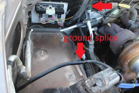
That's a good modification to do. W-T was amazed the factory could have done those grounds so wrong in the first place.
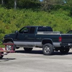
Last year broke elec connection to fuel sender. Dont want to break any more. Any help correct way?
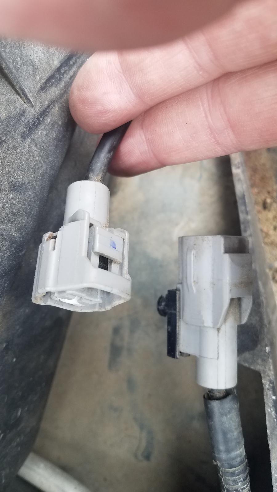
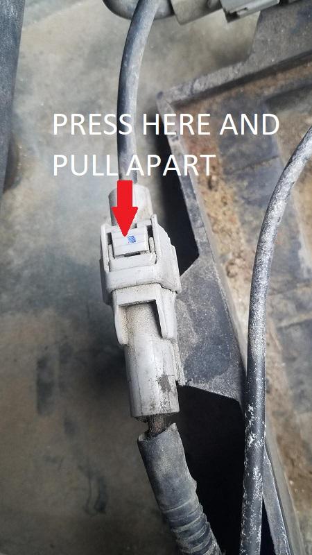
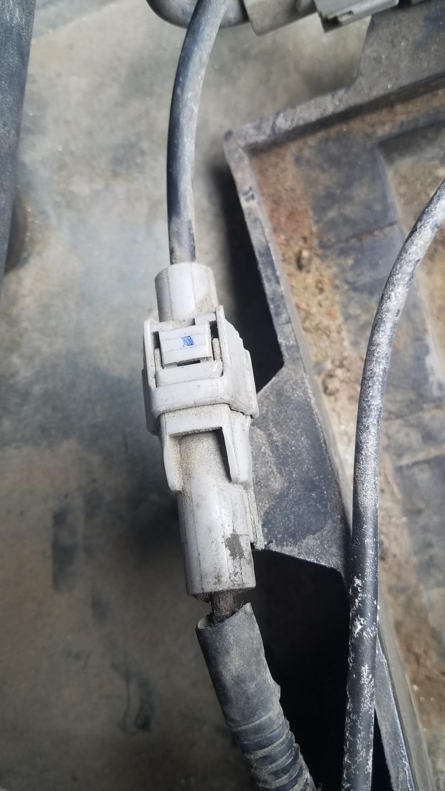
Here is pic of connector to one of the wires from passenger side battery. Afraid to apply pressure the wrong way. Plastic puzzle to me. Little numbers 11184 on connector. Do they need special tools... or what's the secret!
Thanks