


Mopar1973Man
Owner
-
Joined
-
Last visited
Everything posted by Mopar1973Man
-
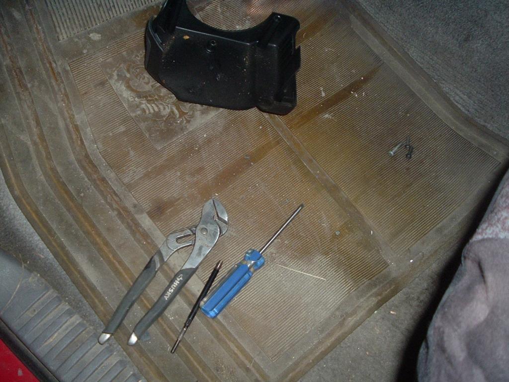
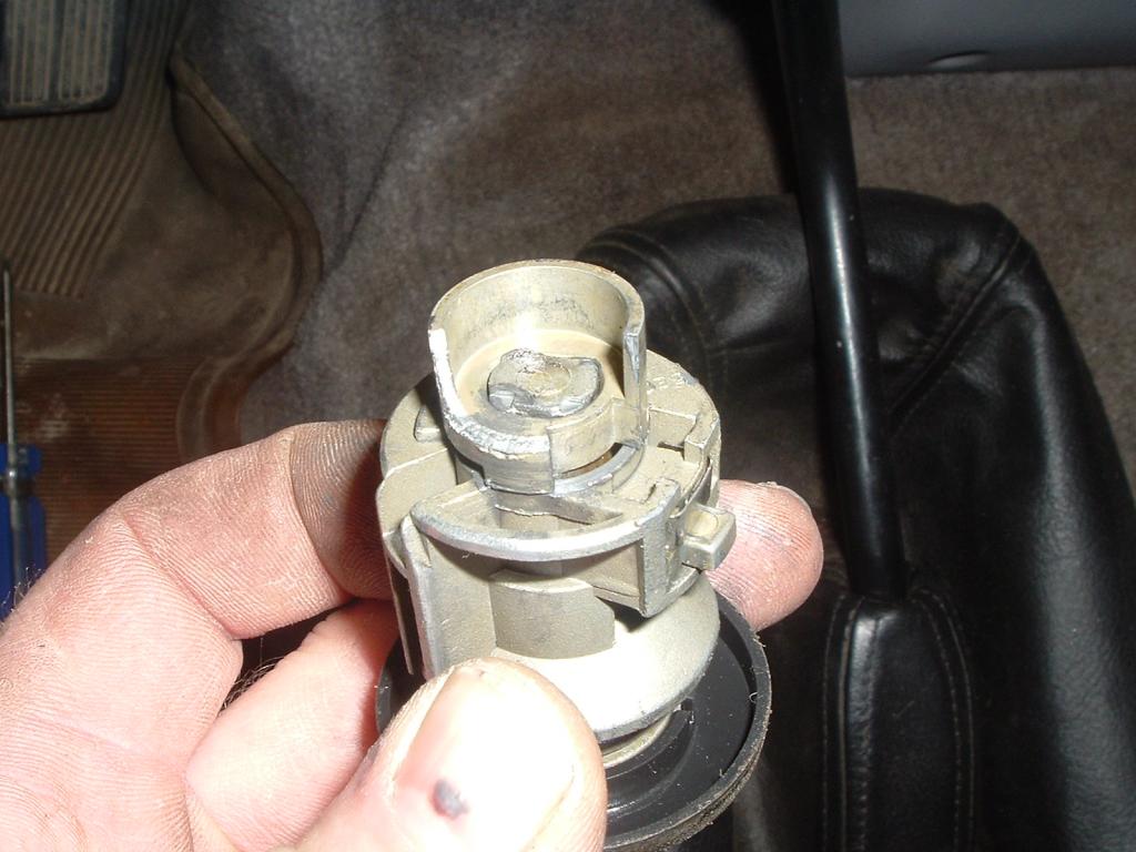
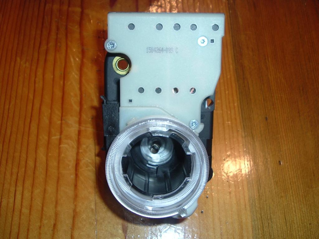
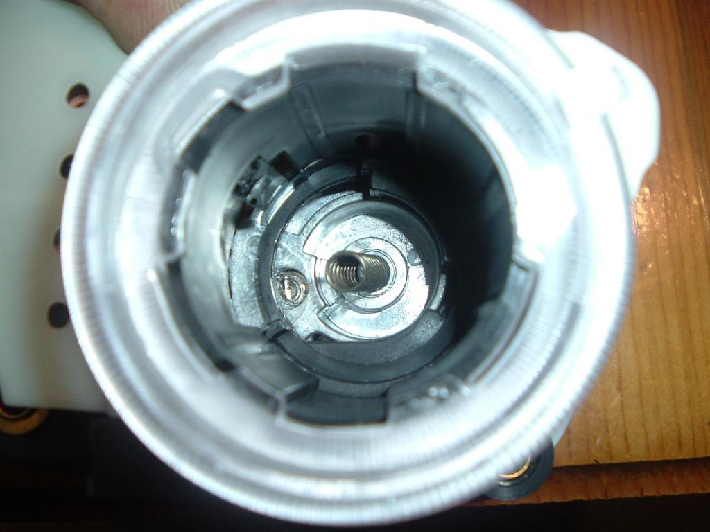
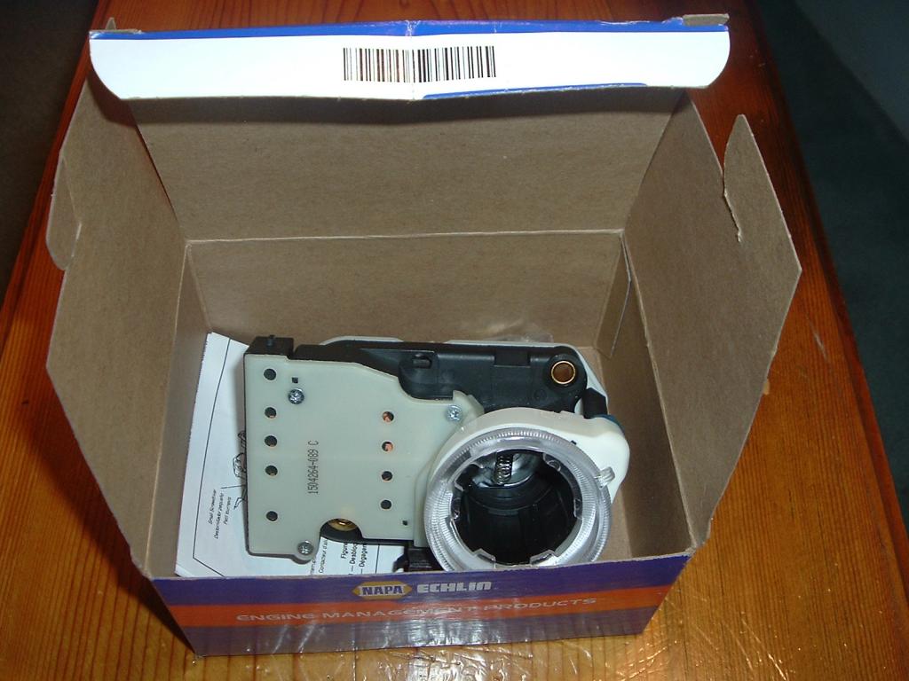
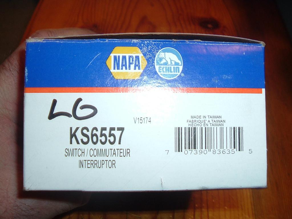
Well I made a few mistakes. But still come to find out I need the lock too. Basically you need a T20 Torx screwdriver. Remove the 3 screws in the bottom of the column. Remove the tilt steering release knob. Remove both plastic covers. My screw up was I misplaced my security bits and found later after doing this next step. I took a center punch and broke the security pins out of the center of the Torx screws. So you need either a T20 security bit or take a center punch and break the center pins out. So what you need to do is remove the locking screw from the switch. My misfortune is that the lock assembly is also damaged. So I've made a phone call to the local NAPA store to find out the lock is $85 bucks. None in stock. So I found the lock cylinder on RockAuto.Com for $34 shipped.

-
Ask Fish & Game what kind of experiments they are doing?
-
Good old "Dripley" can tell stories of how his blew the entire tank off the one side of the radiator... If its in the plastic I say replacement time. Just for the safety value.
-
If its in the plastic tank it most likely a crack forming...
-
Like CSM I also do regular coolant flushes and my cooling system is still spotless inside 13 years later.
-
Just looking at RockAuto.Com there are radiators for $118 to $157... Not bad..
-
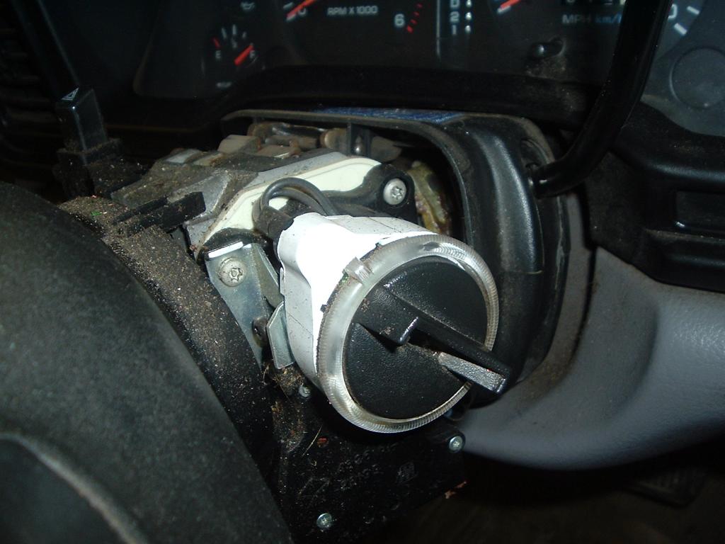
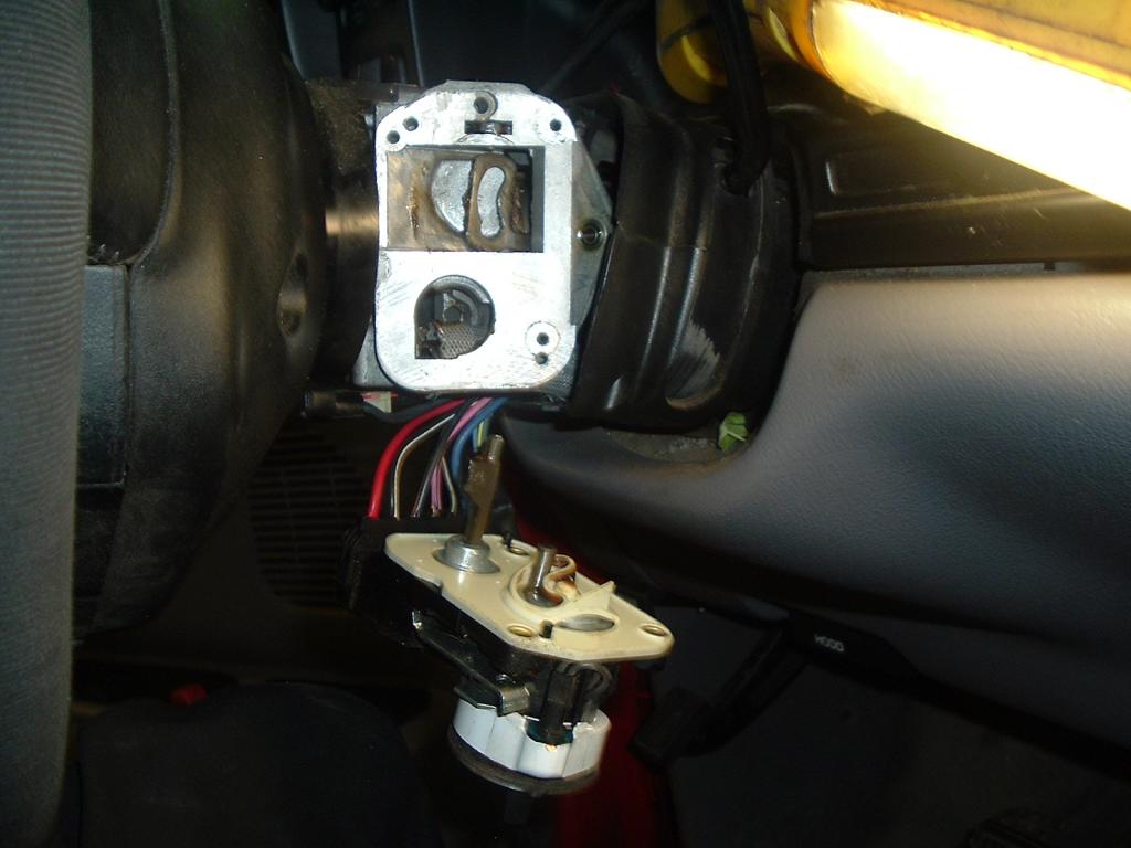
Ok Gang... I'm going to produce a write-up on how to replace an ignition switch and lock assembly for a 2nd Gen truck. More to follow soon. What happen was I took the 96 Dodge into town and load it with fuel brought it back home. Put it away. Later on realized I needed to bring in firewood for the night. So I went out fire up the truck and backed into the wood shed and shut it down. Loaded up with wood in the bed and tailgate. Hopped back in the driver seat turn the key and shock to feel the ignition switch snap internal and the key rolled over without resistance. No ignition, no start. I played with it for quite a little bit and figured out if I pressed the key inward just a bit I could get the ignition turned on. Now I pulled the start relay and jumped between 30 and 87 and got it started. Got the firewood move to the main house and unloaded. Pulled in the garage and shut it down. I can tell you the mechanical part is functional because the key unlocks the steering wheel but doesn't turn the switch for power or start.

-
I agree with you on this. You could but 9 times out of 10 the other 5 are on their way out as well. Like a long chat I had with Jacob @ DAP and Eric @ Vulcan Performance you find that if you send all 6 injectors in and have tested you find typically the other 5 are marginal and should be replaced. Yeah you can replace just the failed ones but performance now is wonky as well couple new and a couple old with difference in spray pattern quality. Then the same old problem couple weeks later here comes the next failing injector. Does it take the piston with it or not who knows? Same reason why you don't change just one injector on a 12V or 24V. Mostly puppies looking for big smoke and not set up properly and street racing with excessive hot EGT's. The other I see is people trying to short cut to big injector and buy just the nozzles without pop testing. As for CR and VP44 there is some differences being the CR is constant feed fuel system and the tight tolerances really do require good filters. Yes plural as in two filters. Again I agree with you about CR fuel system and quality filters.
-
Even going through site vendors 3rd gens are way more for injectors vs. 2nd gens. I can buy 2 VP44 pumps for the price of one set of stock CR injectors.
-
By chance Nick do you still have all your previous version of software?
-
Problem how will it handle the high current draw or charge rates of 140 Amps? How about grid heater cycling in and out? Assuming that diode would require a heck of a heat sink? Mounting location under the hood wouldn't work in the summer time.
-
Dead pedal is when it only idles. Limited pedal is when you press it and you get some throttle but typically limited to a very low speed.
-
Here is Vulcan at barely over $1,000 http://www.vulcanperformance.com/Bosch-VP44-p/vp44.htm Here is DAP... http://dieselautopower.com/bosch-027-vp44-fuel-injection-pump-standard-output-235hp-wire-tap-voids-2-year-warranty-vp44027/ Oh... BlueChip you have to pay at least $1,800 for a pump with a new PSG unit where both list above come with new PSG and been calibrated on a bench.
-
A reman'ed VP44 is just about $1200. P7100 conversion is about $3800. Not to mention all the things that won't work after conversion. You need to stop by either DAP or Vulcan Performance.
-
You can't use the engine that's for sure. VP44... Hard knowing again how he's treated the pump. Most people get the raw end of the deal buying used pumps.
-
I'm going to assume its the TIPM. I know AH64ID or Wild & Free can answer this one.
-
Time to get a Denny T fuel pin and turn up the fuel screw. http://www.dennytperformance.com/FuelPins/index.html Here is a stock...
-
Still a rather wide span of pressure drop. Like Mine is 17 PSI at idle and 15 PSI at WOT. I might drop to 14 PSI in subzero operation. But goes to so how 1/2" lines vs. 3/8 lines are better stablity of pressure. But you also take in the loss on the DDRP I think it what a 100 GPH or 95 GPH vs. my 150 GPH setup.
-
Holy Cow that little rig just exploded!
-
When you go to wrap that loom back up take your time and you can make some really beautiful looms without the buckled up tape, skipped spots, etc. There is a art to doing wiring looms and making them look good.
-
Heater Core Performance Before performing the following tests, refer to Cooling for the procedures to check the engine coolant level and flow, engine coolant reserve/recovery system operation, accessory drive belt condition and tension, radiator air flow and the fan drive operation. Also, be certain that the accessory vacuum supply line is connected at the engine vacuum source. Maximum Heater Output Engine coolant is delivered to the heater core through two heater hoses. With the engine idling at normal operating temperature, set the temperature control knob in the full hot position, the mode control switch knob in the floor position, and the blower motor switch knob in the highest speed position. Using a test thermometer, check the temperature of the air being discharged at the HVAC housing floor outlets. Compare the test thermometer reading to the Temperature Reference chart If the floor outlet air temperature is too low, refer to Cooling to check the engine coolant temperature specifications. Both of the heater hoses should be hot to the touch. The coolant return heater hose should be slightly cooler than the coolant supply heater hose. If the return hose is much cooler than the supply hose, locate and repair the engine coolant flow obstruction in the cooling system. Refer to Cooling for the procedures. An alternate method of checking heater performance is to use a DRBII It scan tool to monitor the engine coolant temperature. The floor outlet air temperature reading should be no more than 4.5° C (40°F) lower than the engine coolant temperature reading. Obstructed Coolant Flow Possible locations or causes of obstructed coolant flow: Faulty water pump. Faulty thermostat. Coolant temp should still reach 190-195*F for proper operation. Pinched or kinked heater hoses. Improper heater hose routing. Plugged heater hoses or supply and return ports at the cooling system connections. A plugged heater core. If proper coolant flow through the cooling system is verified, and heater outlet air temperature is still low, a mechanical problem may exist. Mechanical Problems Possible locations or causes of insufficient heat: An obstructed cowl air intake. Obstructed evaporator. Obstructed heater system outlets. A faulty, obstructed or improperly installed blend door. A faulty blower system. A faulty A/C heater control. Also, want to note that you need to pull the HVAC case completely to do the job right. I've done several heater cores for locals here and it seem fairly typical the evaporator is partially plugged up with dirt, dust, grass, pine needles, leaves, hay, etc. Heater Core Diagnostics Are you fighting to get heat from your heater in the winter time. Barely even luke warm? Well I'm going to guide you on how to resolve this issue. Heater Core Performance I hear it all the time, "If both hoses to the heater core are hot then the heater core is working good." This is totally wrong. Heater core is just minature radiator. If you check your main radiator it should be hot on the upper hose which is return from the engine and cold on the lower hose which is the return to the engine. Same this goes for heater cores. The hose from the head is the supply hot lead. Then the other hose hook to the steel tube is the return. So with just your bare hand if you grab the hot side hose it should be pretty darn hot and you shouldn't be able to hang on to that hose at full 190-195*F coolant temperature. So remember this could burn you be careful. As for the cold side hose it will be warm yet but much cooler than the supply hose it should be about 110-120*F roughly if your heater core is working well. Because your transfering the heat into the cab. If not you'll most likely end up replacing the heater core because its plugged up and both hoses are hot. Vent Temperature If the heater core is working properly you should be capable of reaching 150-160*F vent temperatures on any fan setting. Blend Door You might have to check the blend door operation. Typically with the ignition key in the ON position and the engine OFF you should be able to turn the temperature knob from cold to hot and see the stem of the blend door move. If your not seeing a good control of the cold to hot you might have to pull the stepper motor and replace the blend door stem. This is supplied from Heater Treater. This stepper motor is on the passenger side of the dash right along the transmission hump you can miss it. Coolant Condition If you got green coolant and its been over 50k miles you should consider a cooling system flush. If your using yellow or orange coolants they are rated for 100k miles typically. But I suggest you consider using coolant test strips to test the pH level of the coolant if your going for long change periods. I normal would do a full system flush with fresh water to rid the system of any corrosive coolant and any debris. Thermostat Performance I see it quite often where people post on forum where there engine temperture rarely even gets close to 190*F. This is a sign of a failed thermostat. Stock all 1998.5 to 2002 Dodge Ram with Cummins should have 190*F thermostat. 180*F thermostat is not recommended. If your having problem getting to 190*F or holding 190*F coolant temperatures then the thermostat has failed. A good thermostat will typically float right around 193-197*F in normal operation. So this should be dispalyed on your gauge as being right at or just right of the 190*F mark. You can get a replacement thermostat at your local NAPA store.
-
HVAC Case Removal WARNING! Disconnect the batteries for at least 15 minutes before starting to disassemble the dash. This is because of the Air Bags in the dash. This is just a safety precaution to keep the possibility of discharging your Air Bags while you work on your dash. So that being said we'll disconnect the batteries and work under the hood for a short period. There are a few chores we got to do under the hood. Drain at least 1 gallon of coolant Disconnect the heater hoses Remove the Air-filter Assembly Discharge the freon from the Air Conditioning System Disconnect all A/C plumbing to the evaporator Remove the 4 nuts holding the HVAC unit on the firewall On the driver side of trans hump disconnect the vacuum lines to the HVAC Now as for the fast way to access the HVAC unit you need to remove all 5 screws all the top of the dash. Then pull the knee bolster and remove the 2 nuts holding the steering column and allow it to lay on the driver seat. Then remove both kick panels and loosen both bolts at the base of the dash. Now in the center (SRS computer) there is 2 bolts and 2 nuts holding the center of the dash these have to be removed. Now gently lift the dash up and out of the slot in the passenger side bolt. Using a tie strap hang the dash from the grab handle on the passenger side. Note: You may add a note on automatics to remove the shift indicator cable before dropping the steering column. (Oldbeek) Disconnect any wiring going to the HVAC unit. Now there are 2 nuts on the dash side you got to remove. Now the HVAC unit will slide out under the dash on the passenger side. You'll have to lift the dash slightly but it will come out easy. Heater Core Removal Remove the 3 Phillips screws and lift the heater straight up out of the HVAC unit. Evaporator Removal Flip the HVAC unit upside down. Now find the floor vent and careful unsnap the floor vent and remove the first Phillips screw. Then remove the remaining Phillips screws around the edge. Now carefully pry the two halves apart. The picture below is including the heater core so you see part placement. But the heater core was removed in the earlier process. Make sure you have new foam to reseal both the heater core and the evaporator if you replace either one. Take the time and clean the HVAC case and any heater core or evaporator that you re-use. Now during assembly is careful of the spring loaded door on just left of the blend door. Really easy to crush this little door so take your time and pay attention to this spring loaded flap. Also, make sure to line up the blend door pivot with the hole in the other half. Don't force anything! Additional Information I want to bring attention to CF article about a short cut method of changing heater cores without pulling the HVAC case. It's possible to do this method but I highly suggest against this. When you remove the entire case and split it open you are able to inspect everything from the blender door plastic shaft to the evaporator. If you do the shortcut method you cannot inspect the evaporator nor clean it. In the pictures below I was able to use a 3,000 PSI power washer and clean the evaporator to re-use it. The owner told me his heater now is way stronger and hotter. He's got to roll down the window to cool off. In other words, it way better to invest the extra time and effort to pulling and doing the job right.
- 4 comments
- 5 reviews
-
-

- 3
-
-
Turbo Inspection Operation Exhaust gas pressure (drive pressure) and energy drive the turbine, which in turn drives a centrifugal compressor that compresses the inlet air (boost pressure), and forces the air into the engine through the intercooler and plumbing. Since heat is a by-product of this compression, the air must pass through an intercooler to cool the incoming air and maintain power and efficiency. Increasing air flow to the engine provides: Improved engine performance Lower exhaust smoke density Improved operating economy Altitude compensation Noise reduction. The turbocharger also uses a wastegate, which regulates intake manifold air pressure and prevents over boosting at high engine speeds. When the wastegate valve is closed, all of the exhaust gases flow through the turbine wheel. As the intake manifold pressure increases, the wastegate actuator opens the valve, diverting some of the exhaust gases away from the turbine wheel. This limits turbine shaft speed and air output from the impeller. The turbocharger is lubricated by engine oil that is pressurized, cooled, and filtered. The oil is delivered to the turbocharger by a supply line that is tapped into the oil filter head. The oil travels into the bearing housing, where it lubricates the shaft and bearings. A return pipe at the bottom of the bearing housing routes the engine oil back to the crankcase. The most common turbocharger failure is bearing failure related to repeated hot shutdowns with inadequate “cool-down” periods. A sudden engine shutdown after the prolonged operation will result in the transfer of heat from the turbine section of the turbocharger to the bearing housing. This causes the oil to overheat and breaks down, which causes bearing and shaft damage the next time the vehicle is started. Letting the engine idle after extended operation allows the turbine housing to cool to normal operating temperature. Mopar's Notes: You should allow your pyrometer to fall below 300°F before shutdown. If you don't have a pyrometer I highly recommend you purchase a pyrometer gauge and install it. There is also turbo timers that allow the driver to turn off the ignition and lock up the vehicle. The engine will continue to run for set time and then shut down. These add-ons will extend the life of your turbo greatly. Turbo Inspection Procedure Visually inspect the turbocharger and exhaust manifold gasket surfaces. Replace stripped or eroded mounting studs. 1. Visually inspect the turbocharger for cracks. The following cracks are NOT acceptable: Cracks in the turbine and compressor housing that go completely through. Cracks in the mounting flange that are longer than 15 mm (0.6 in.). Cracks in the mounting flange that intersect bolt through-holes. Two (2) Cracks in the mounting flange that are closer than 6.4 mm (0.25 in.) together. 2. Visually inspect the impeller and compressor wheel fins for nicks, cracks, or chips. Note: Some impellers may have a factory placed paint mark which, after normal operation, appears to be a crack. Remove this mark with a suitable solvent to verify that it is not a crack. 3. Visually inspect the turbocharger compressor housing for an impeller rubbing condition (Fig. 25). Replace the turbocharger if the condition exists. 4. Measure the turbocharger axial end play: a. Install a dial indicator as shown in (Fig. 26). Zero the indicator at one end of travel. b. Move the impeller shaft fore and aft and record the measurement. Allowable end play is 0.038 mm (0.0015 in.) MIN. and 0.089 mm (0.0035in.) MAX. If the recorded measurement falls outside these parameters, replace the turbocharger assembly. 5. Measure the turbocharger bearing radial clearance: a. Insert a narrow blade or wire style feeler gauge between the compressor wheel and the housing(Fig. 27). b. Gently push the compressor wheel toward the housing and record the clearance. c. With the feeler gauge in the same location, gently push the compressor wheel away from the housing and again record the clearance. d. Subtract the smaller clearance from the larger clearance. This is the radial bearing clearance. e. Allowable radial bearing clearance is 0.326mm (0.0128 in.) MIN. and 0.496 mm (0.0195 in.) MAX. If the recorded measurement falls outside these specifications, replace the turbocharger assy.
-
Years ago on my 1973 Dodge Charger I was taking the time to rebuild the rear bumper and tail lights. I found a local hardware store tha had the friction tape that was absolutely the same stuff as what Dodge used back in 1973 on the tail lights.
-
Gelled?
