Mopar1973Man
Owner
-
Joined
-
Last visited
Everything posted by Mopar1973Man
-
... and a can of diesel.
-
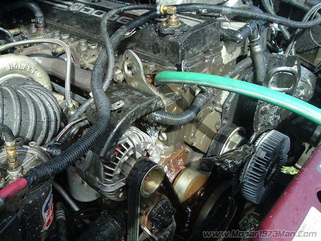
I'm the same way. I'll power wash the engine before and after so my working environment is clean as well as the vehicle looks clean for the owner. Only take a few extra moments to wash it down before and after. Makes finding leaks easy this way to. Just follow the wet spot.
-
I'll make sure to bring my weed torch. I'm not going to get suckered into that job...
-
Like I'm using a product from Home Depot right now that is a purple cleaner of sorts. Works wonders on greasy engines and under vehicles. Power washer with 15* angle tip is awesome for cleaning with. If you use a 0* angle tip it's like a laser beam and kind of a pain in the rear. But it's the most powerful for cleaning things that are caked up. Typically the rest of the truck I'll wash with a 40* angle tip much milder.
-
Be careful with water pressure. Like myself, I've got 116-118 PSI at the faucet. Won't take much to blow a heater core. Correct way of fixing it but not cost effective is to pull the heater core out and rod the core out.This only works if you have the old brass core because you can remove the header and rod it out. I've done this in the past and it typically ends up with a leaking core anyways because the tubes tend to get thin if they have scale build up. Typically from corrosive coolant and oxidizing the metal and then condense then into solids at the coolest point heater core and radiator. So you better off just replacing it most times.
-
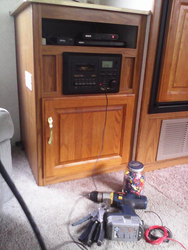
No I hauled my tablet out to the RV for tunes. Then thought about the clips for the blinds and figured I would post the picture of the stereo. I had to pull it out to re-wire my propane detect again. Crappy scotch-loc's and Not sure if the propane alarm is any good. Do some testing on it. I'm hunting for a quality blind clip that is made from softer plastic that is semi-flexible. I've got some white plastic clips that do exactly this. Then the clear ones you find every where are super brittle and easy to break just trying to release the blinds. Does anyone know of a good place to find these semi-flexible blind clips? Help! I really do hate to pull up blind before I travel or forget and find them all beat up fro swing wild.
-
Good point. It would be a good idea to flush the system before hand. @notlimah Doing a heater core isn't bad. I've done my fair share of those and not hard. Just that you have to discharge the A/C system to unhook everything. Best to do it right. It sure would suck to do a half job and find out the evaporator is plugged up. Like this owner tells me now he has to roll down the windows to cool off because the heat is so strong now. So all I can say is bite the bullet and pull the entire HVAC case out and inspect everything. Oh this evaporator ran mud while rinsing it out with 3,000 PSI power washer.
-
-
About 10-20% chance that doing that will fix anything. The other bad problem is is there is any debris in the block it will plug right back up in a short time. So very rare that anyone cures a poor heater core by flushing which still points to a debris issue in the rest of the cooling system.
-
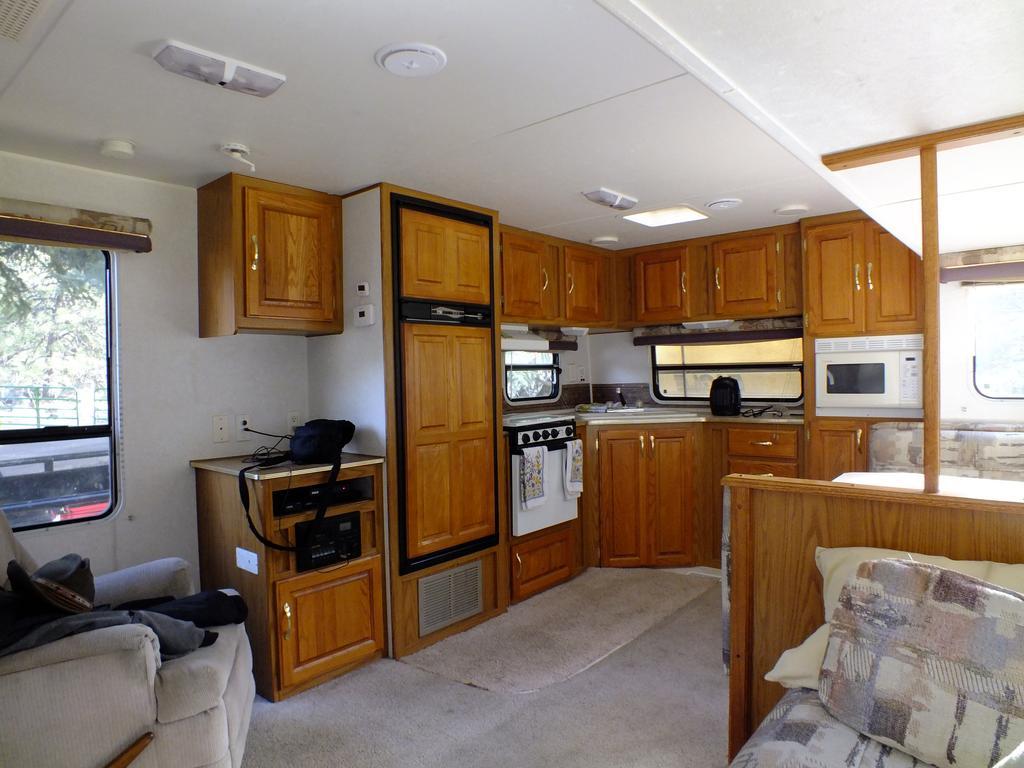
Now I'm hanging out in my man cave. Cleaned up the RV fixed few minor things like table bracket and then a few wiring issues. Pretty cozy out here. I need to find blnd clips that are not not the cheap clear plastic I keep breaking.

-
If your closer to me I charge $60 an hour shop rate and typically do a VP44 in about 2 hours. I'm I'm isolated here too. I'm 180 miles from any large city with anything.
-
Tweak that just a bit. Wipe both out clean then spray one end with WD-40 and then tell him the cleanest one get a free lunch... WD-40 will trap and flowing dust and debris on the walls of the tube.
-
Most heater issues are because of plugged heater cores. Then the next is the blend door coupler but usually there is a complaint of lack of control as the door swings back and forth freely.
-
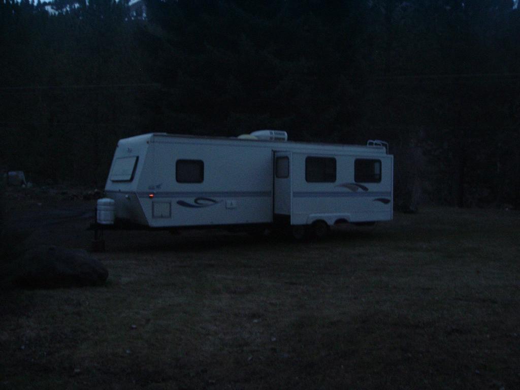
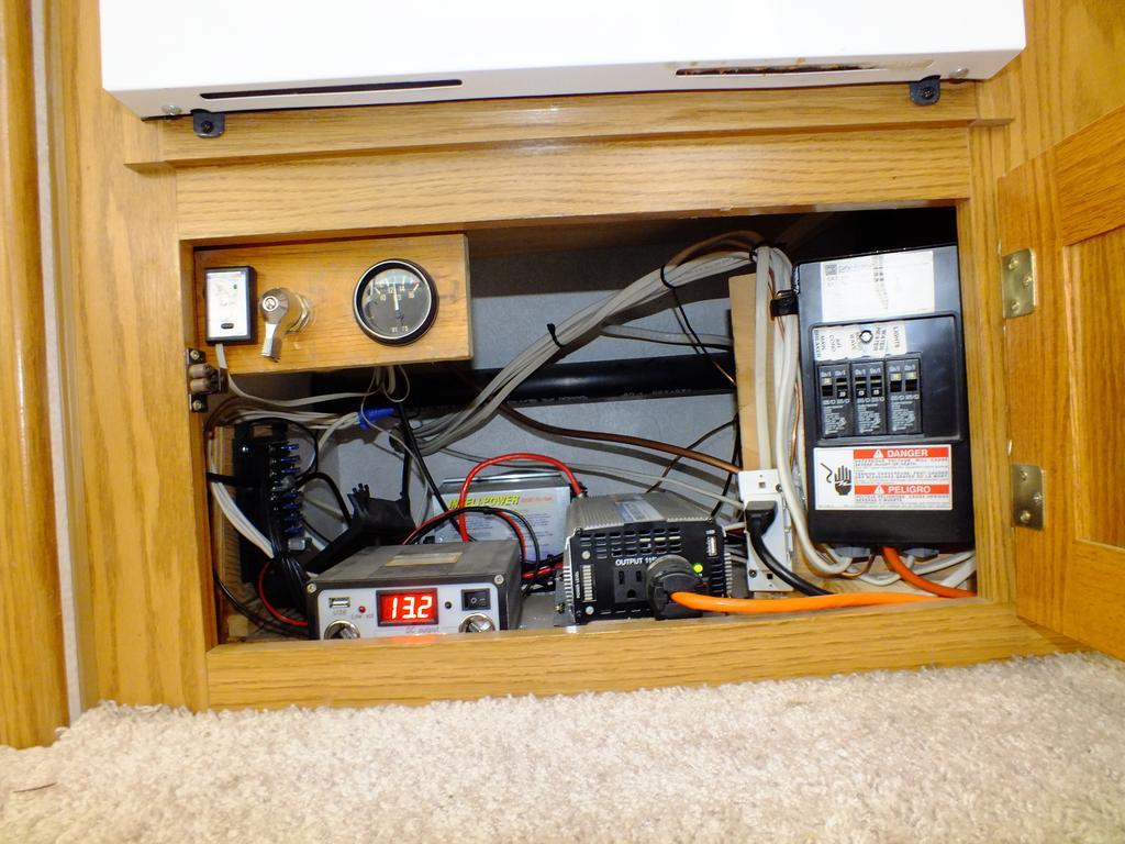
I just had to do it. Nick over there talking about his slide in camper so I hitch up and moved mine out from under the tree. Then started to clean up the inside from all winter of sitting. Lots of dead flies, and other little critters to clean up. Just to show off the mobile man cave. Nice and roomy with the slide out. Bring it back in well it's tight but you can still use it. Full size queen bed not one of those short RV queen beds. A better picture of the power cabinet with the inverter, solar controller, converter, fuse panel and breaker box. So I'm on task for getting the RV ready for another season of camping. Damn you Nick its all your fault...

-
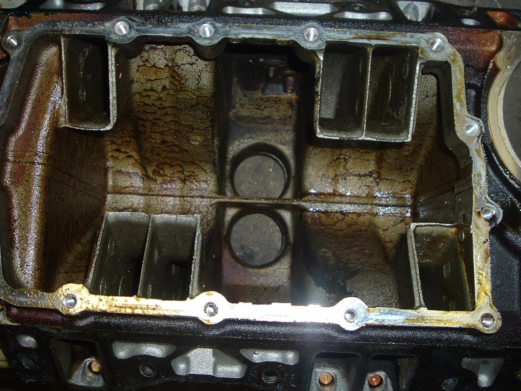
Looks like dusty roads and puddle jumping was occurring. Inhaled lots of dusty water. Just great for an engine. Trust me guys I'm going to show him this thread when he comes to pick up his truck.
-
You might trim a bit of floor foam out to make for better access.
-
Even what people have done coolant filter wise on a Cummins typically it's installed on the heater hose. Me personally I would dump the coolant and flush the entire system till the water is clear and reload with fresh coolant.
-
That why in the summer time I love to go out wood cutting. Get up to 7,000 feet is a nice 70's day. Return to Riggins, ID it could be as high as 115*F. So summer time means more camping for us typically.
-
Ok Gang... I've got a for sure way to diagnose torque converter lock up issues where it lock and unlocks at about 45-50 MPH. I had a gent call me yesterday with this problem and he's replace both batteries, alternator and the APPS sensor. Attempted all the different wiring issues (adding ground, tinfoil etc.) nothing worked. Like I told him the truck ran 11 years without all this stuff and doesn't require any wiring change to make it work. What it needs is the damaged part to be replaced. So he's returned the wiring back to stock setup. Now I told him to unhook the alternator fuse and take it for a ride... Guess what... No problems! Even though he replaced the alternator it has a damaged diode in it and it bleeding AC noise into the electrical system. So before doing any wiring mods, tinfoil, adding grounds, adding filter... PLEASE! Bench test your alternator! This is the second time I've suggested this and both time resolved the torque converter lock up issue. What is bugging me to no end is the fact there is all these wild write up of people adjusting APPS sensors, wiring mods, extra grounds, filters, etc. I still say the truck ran fine without any of these mods for 10-12 years and now it needs it... I doubt highly. I say there is a part that is failed and needs to addressed not band-aided over. The more and more I kept studying this and the more I ran into people with this issue and what they done never resolves the issue. But now this is the second phone call where I helped a owner with this issue and found that just unhooking the alternator fuse and the problem goes away tests me instantly the alternator is at fault... Before starting any electrical testing make sure you main battery cables are up to the job and the terminals are clean. You might head over and to my other article and bench test your cables for function. Voltage Drop Testing of Main Feed Cables Normal output of the alternator is 13.5 to 14.5 volts DC but when flipped over to AC Volts it should never rise above 0.1 volts AC. If it does then you found your AC noise source. Another test is to disconnect the alternator fuse and measure again the battery volts in AC and you notice it drops to zero. This means you found your source of AC noise. Here is a basic alternator circuit... Take notice there is 6 diodes (3 positive and 3 negative) if I should short out in either side that will be the side the AC waveform leak out on... More diodes fail the worse the problem gets. But in the DC life the gauge will continue to read 14 Volts even though the diodes are bleeding AC wave form. Failed diode waveforms will create some unusual patterns which will create the torque converter issues you guys are having. Here is a normal alternator output with good diodes. Here is failed diode patterns... Why am I going out and trying to fix this problem? Because the AC noise created by the alternator is being fed to all systems ECM, PCM, ABS, etc. So there is a chance that some of the random failures of ECM's and VP44 is caused from a failed alternator. To fix this issue you will need to replace the Diodes on the alternator. Here is the Mopar1973man kit for this. Please ensure you troubleshoot your alternator fully and ensure the Diodes are to blame. We will not offer a refund once the Diodes have been installed. Another Member Results As posted from craneop (AKA: Terry Quirk) Forum Post OK! Problem solved! Yippee!!! Took the recently purchased Alternator back to O'Reilly's where I got it from, had them test it on their tester. They told me they run the test 3 times and if they get a PASS all three times, its a good alternator. When I asked about measuring AC Voltage, they looked dumbfounded, so I asked them if I could hook my multi-meter up to the alternator while they tested? They agreed! So now this alternator is reading .35 Volts AC as the first test PASS'S, they run the second test and we get a FAIL, the guy gives me a funny look, checks his wires and runs the third test and we get another FAIL. So the guy now rells me guess we have a bad alternator but they don't have another one on the shelf and I will need to wait till tomorrow to bring one in from the other store. I say, I'm OK with that, but that I've learned my lesson and we are going to have to test the next alternator as well before I leave the store with it. The next morning (yesterday) they call me and let me know the alternator is in and I can come down and pick it up. We do the test like before, and this time we get a PASS, PASS, PASS, however my multi-meter is reading 0.3 Volts AC, and then I also notice that on their machine there is a box at the top that says Diodes and across from that box on the screen says N/A. So I ask the guy about it and he says their machine has no way of testing the diodes, it only test for overall condition of the alternator. Unhappy with what I'm hearing and looking at, I request my money back which they had no problem with at all, however the core I earlier took in was no longer in the store so the gave me cash in the amount of $215.00 (their core charge on that alternator $36.00 along with the full purchace price of $179.00.) By this time I have no core, only to find out all the other auto parts stores around town are charging a $70 - $80 core charge for this alterrnator, and a lot of the places have no tester. Starting to get a bit frustrated, I decided to quit messing around and go to the most reliable place in town I know of, a small family owned auto electric and mechanical shop (Auto Electric, Anchorage, Alaska). I was hoping that maybe they had heard of this isuue I am having with the TCL and get fixed up with a good alternator. They rebuild all kinds of auto electrical parts right there in house as well a run a full service auto mechanic shop. Well,,,,I explained my problem to them and showed them a printed copy of the troubleshooting procedure I got from the Mopa1973Man website, to which they said...never heard of this before. However these guys are real pro's and they didn't blow me off. They took my concerns seriously, brought two techs in out of the shop to talk with me about this, as I explainded to them the 0.1 Volt AC upper limit thing. They genuinly got concerned and were pulling down alternators, checking them on the bench and checking outputs at vehicles in the shop. In all, I was in there for about two hours while they tested and discussed and in the end the shop found me a NEW alternator and gave me a heck of a deal @ $239.00 w/no core charge. The NEW alternator was putting out 0.22 Volts AC on their alternator bench vise, and that concerned me cause I was looking for something under 0.1 VAC. However in further discussion, the techs I was working with concluded, (and BTW they turned out to be right), that the test machine itself was putting off AC Noise and that the Fluke Meter was picking up that AC Noise during the test, and that since the Voltage Regulator is on either the PCM or ECM, the only way to accuratly read out the AC output on this alternator was to put it on the vehicle and measure it at that time. So,,,I took the alternator home, hooked it all up, and WALLA... measured at the battries -0.01 Volts AC @idle, and 0.00 Volts AC @2000 RPM. Feeling pretty good at this point I take it for a test drive. Runs and shifts perfectly. NO MORE PROBLEMS!!! Cory, I believe he's the manger or maybe owner, at Auto Electric said though he's heard and dealt with a lot of Dodge Cummins issues like this before, had never heard of this shifting problem being linked to + 0.10 VAC output on the alternator. He asked me to check back in with him to let him know how all this worked out. I will do that on Monday, as well as express my thanks for all the personal attention, efforts and concerns Auto Electric gave to me to adress my problem. In the meantime, my utmost gratitude to Mopar1973Man for sharing your knoweledge and wisdom on this issue. I had tried all the bandaid tricks only to have them each work for anywhere to a couple hours to a couple days or so and then reappear. I believe what was happening was that as I fixed a ground or foiled a wire, it masked the problem just long enough for the diodes on the alternator to get a little worse and then BOOM, the problem is back! Very good information Mopar1973Man!!! Happy Holidays!!! Update: November 19, 2014 Here we go with another blown alternator confirming without a doubt of the diodes being a cause. Before any repair... http://forum.mopar1973man.com/index.php?/topic/4988-torque-converter-lock-unlock-issues/page-10#entry100230 After the alternator is rebuilt... http://forum.mopar1973man.com/index.php?/topic/4988-torque-converter-lock-unlock-issues/page-10#entry100294 The cause...
- 1 review
-
-

- 1
-
-
It'll be back next winter...
-
Sucks to be you Dave... Low this morning of 33*F and hi of 47*F. I know down south its just a bit warmer.
-
Don't understand your last comment.
-
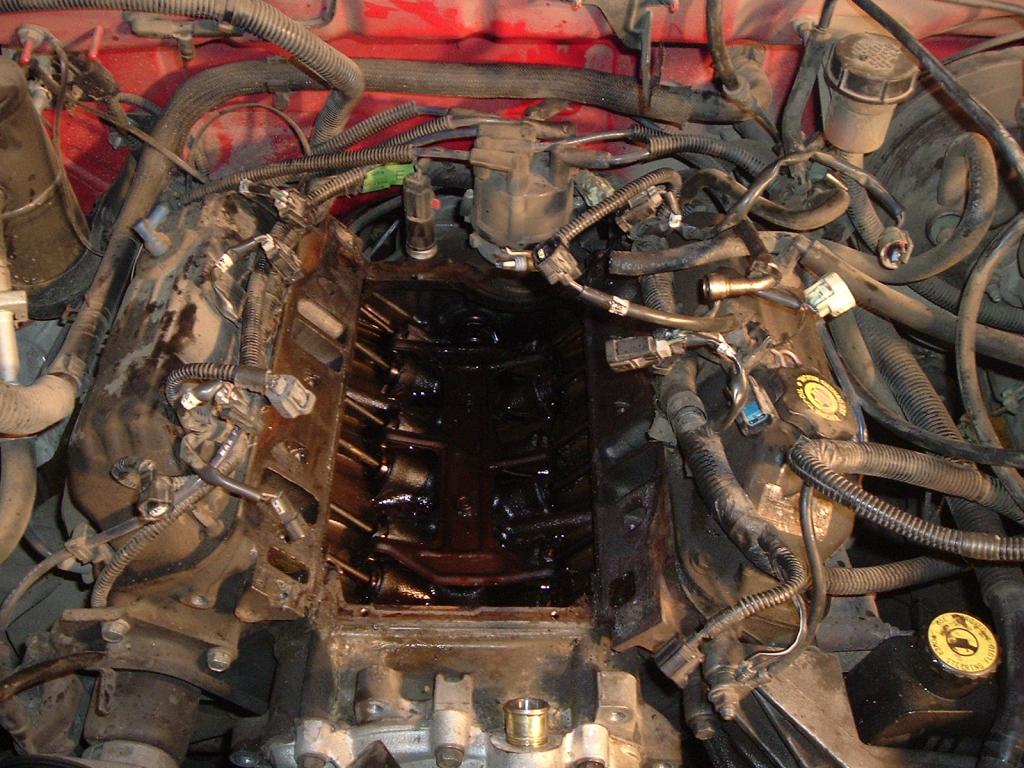
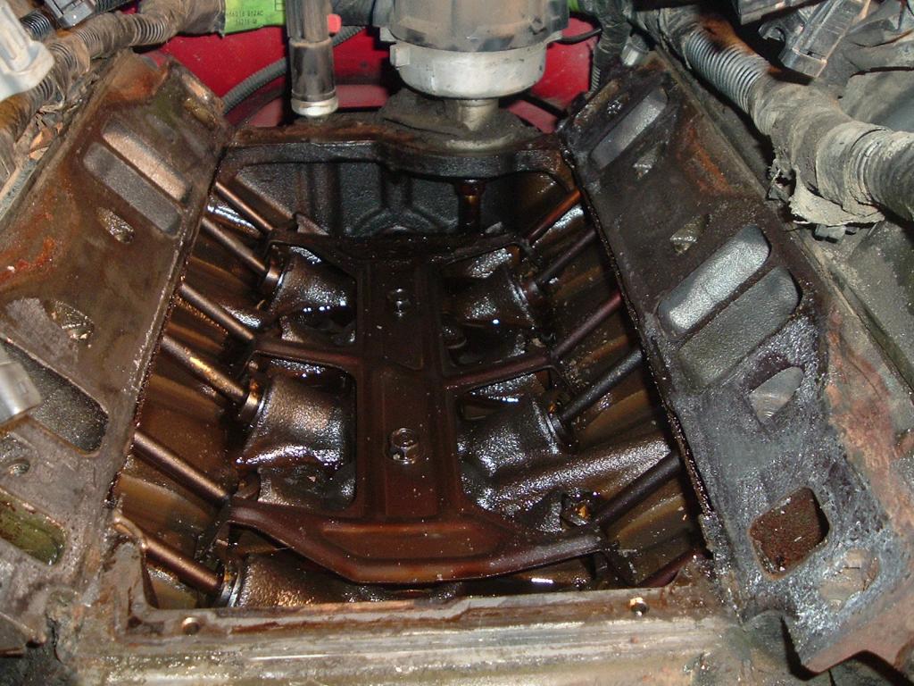
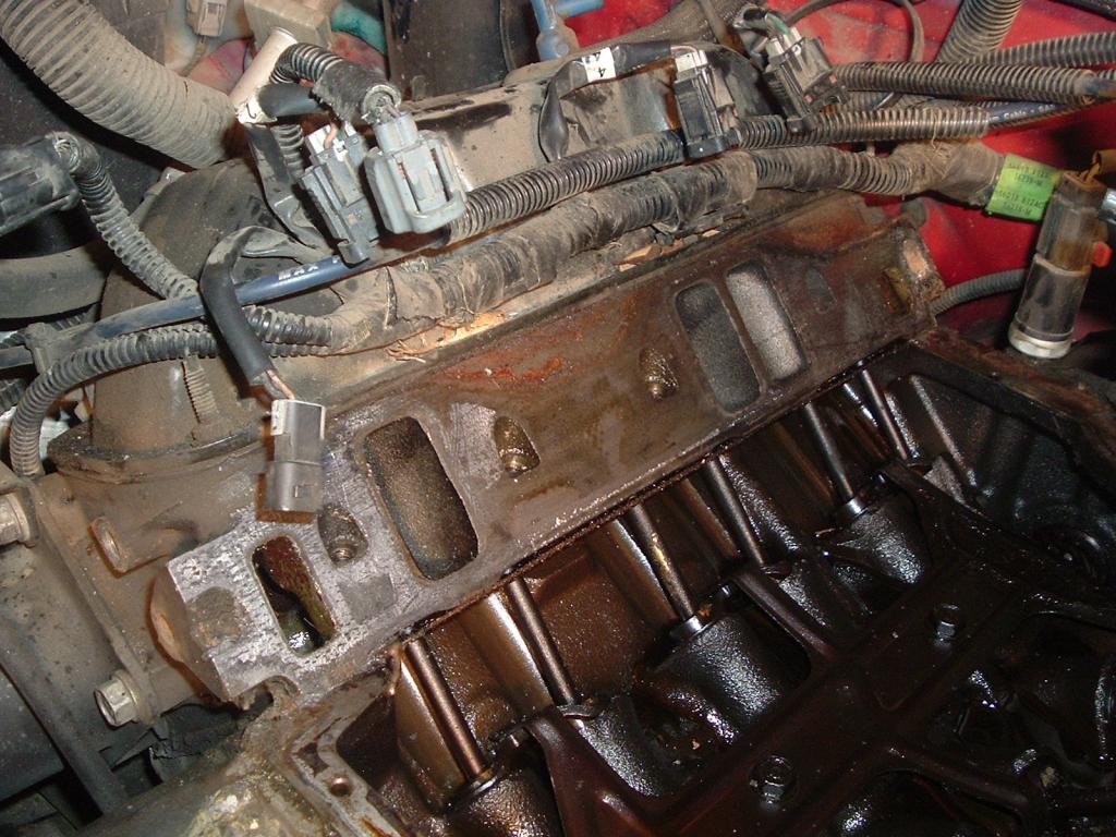
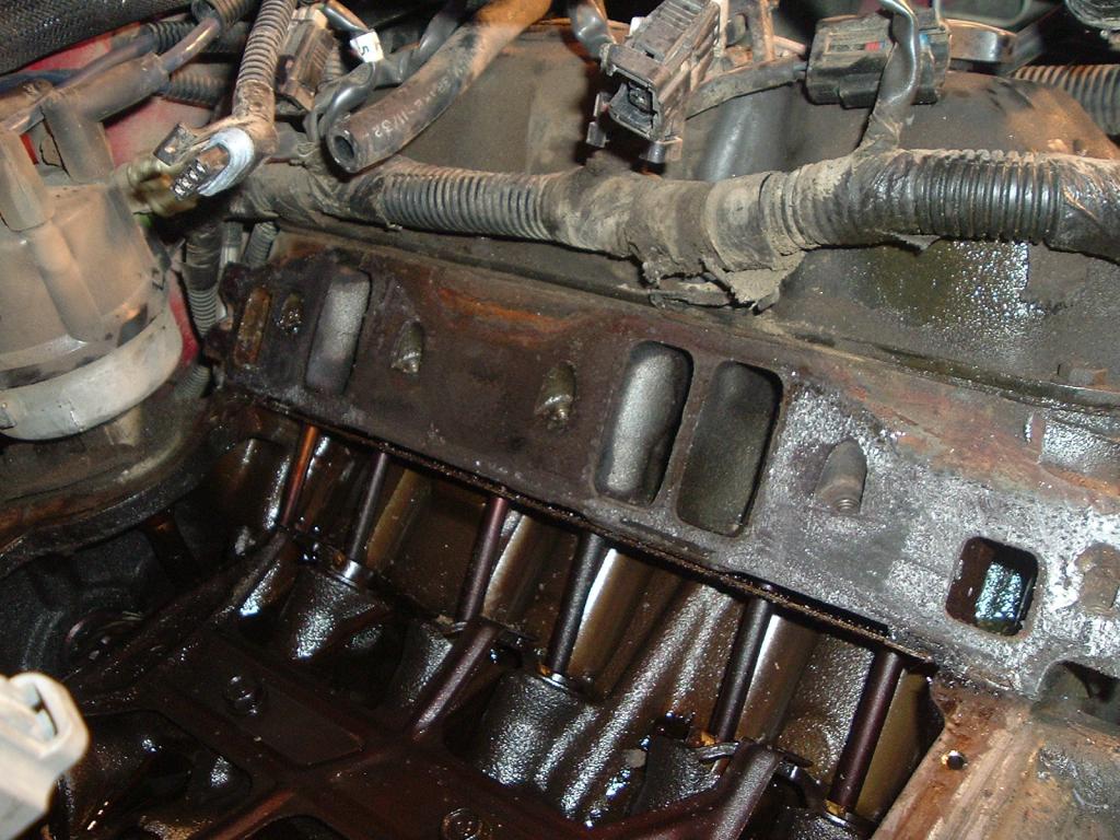
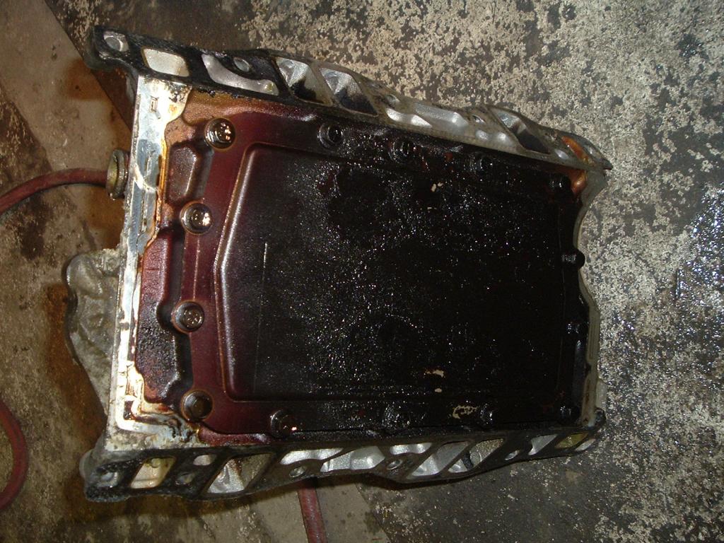
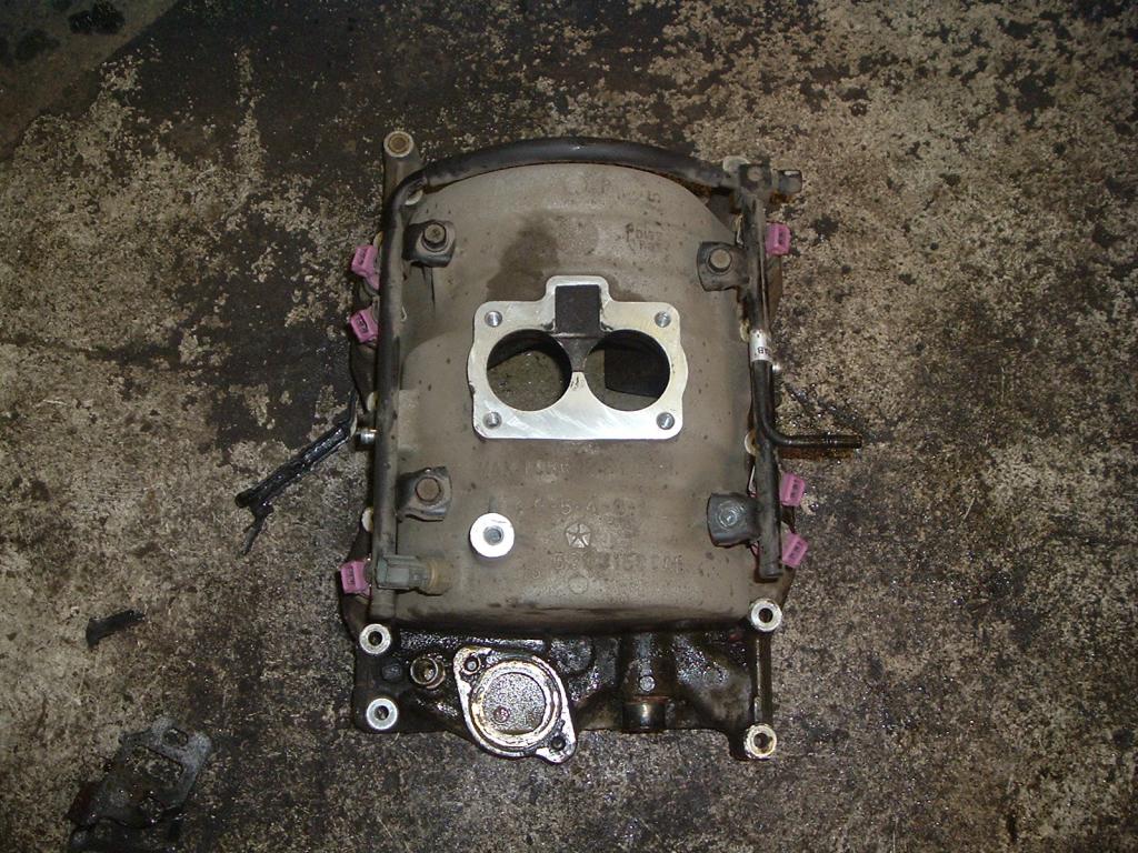
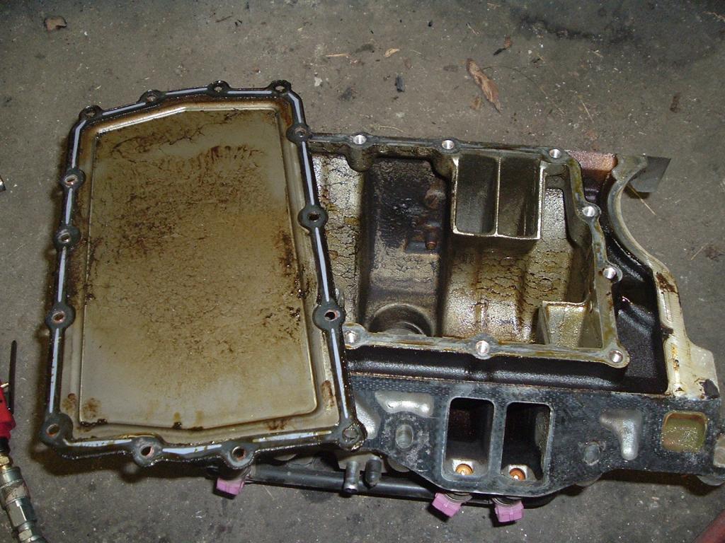
Another job dropped on my door step. Local gent was having issues with his Dakota with a misfire code P0304. It's the little V6 engine. So I told him to order the gasket for me and drop it off and I'll get it changed out. You'll notice the oil in the inside of the manifold which is typically when the plenum gasket fails. It will start drawing air from the cam valley drawing in little bits of oil. The owner also admits the truck had a K&N filter. You'll see the amount of grit and dirt let into the manifold. Little trick to pass along is while your scrapping the manifold gasket off take a shop vacuum and keep it near the area your working and the vacuum will pull in the bits of gasket material as you scrap. Nearly nothing for debris in the cam valley this way. When torquing the bolts for the plenum and the manifold you need a INCH / POUND torque wrench. Manifold is final torque at 12 FOOT / POUNDS or 144 INCH / POUNDS. The plenum is final torque 84 INCH / POUNDS. Nice part is when I fired it up the miss is gone and the CHECK ENGINE light went off by itself. Yes. I'll clear the codes to make sure the slate is clean.
-
I called the cable manufacture I had him break it into 2 batch so we can get them sooner.
-
Weather getting so mild I've pulled mine out so I can start cleaning up everything from winter time. Might sneak out soon for a trip south. I've got to re-seal around my clearance lights and some of the trim. Darn delamination in a few spots. It's all your fault Nick you started a trend...