


Mopar1973Man
Owner
-
Joined
-
Last visited
Everything posted by Mopar1973Man
-
I tend to agree it sounds like your picking up a bit of a air in the fuel.
-
I'll try that next time. Sounds like a awesome way to go for cleaning. Yeah it was poor planning on my part and then get word of a sudden shift in weather so I drain it out and pumped it up. Takes exactly 1 gallon to load my system with pink antifreeze.
-
So I spent a better part of my day out in the RV. I mixed up a bucket of simple green and water and proceeded to wipe down the entire RV. Just about ready to start packing the stock of goods back in the RV. Making sure there is enough TP and tissue for blowing the beak in the morning. Scrubbed the stove and oven. Wiped down the fridge and freezer. Last thing will be flushing the anti-freeze out of the lines. I normally don't use anti-freeze in the RV. Last fall the cold weather came so fast I just grabbed the pink stuff and pumped it in the system. I really hate using it. It will still freeze solid but they claim it doesn't expand. Only problem is if there is any water in the line it will expand.
-
@IBMobile Now those are what I would buy http://www.fixmyblinds.com/1-Metal-Hold-Down-Bracket-12-p/hdb-12.htm
-
Just clean up and buy a BHAF and be done with it.
-
This is my 4th pair of clips now going for my 5th pair. I need actually 2 more pairs of clips. Rolled over in bed arm/hand hit the blind bottom rail and broken the clip. The other I turn in my chair and the back corner push on the blind. (snap). Had a friend sleeping on the couch on night same thing rolled over smacked the blinds and pop goes another. I shouldn't have to replace 2-4 clips every spring time.
-
Fully 190-195*F coolant temp with below freezing outside air.
-
Hmmm... No comments on the blind clips eh? Crap I guess I'll just take pot luck again...
-
I see you don't have any hot water in that camper. Nothing wrong with heating water on the cook stove. Starting to come together.
-
Funny... I know of the guy. I didn't realize that was him down there in that mess. http://www.oregonlive.com/oregon-standoff/2016/02/who_are_remaining_occupiers_se.html
-
I would love to just play with SCIpod software and a programming cable. Yes, I still got it. Should get ahold of the gent that was doing that and see if we can jump into that project for education purpose. You know who I mean.
-
I'm going to assume the oil pressure, crank sensor and MAP sensor are all on the same 5 volt. I bet the oil pressure sensor was shorting out the 5V line caused loss of crank signal ans well as the MAP codes. Now the other 2 pin sensors I'm going to assume are on a totally different 5V system because of their nature. The 5V and sense is inside the ECM then bias from sensor ground with resistive sensor. The other system is a separated 5V and sensor set up so I can see thing being different.
-
Just to show off Nicks handy work say I'm looking for a set of new hood bumpers for my 02 truck. So I would go over to the part number lookup tool and find the part I'm looking for. Now go over to Google and type in the part number plus "dodge ram". https://www.google.com/#q=02276804+dodge+ram Now just quickly checking the reported links. The first one for me had what I was looking for at a god price even. http://www.factorychryslerparts.com/products/DODGE/RAM-1500/BUMPER-Hood/4240073/02276804.html So this should help folks find parts for there trucks even the tougher ones that most part stores might not have.
-
One to put in the articles. How a bad oil pressure sensor can pull it down.
-
First off. The only sensors you need to make it run is Crank and Cam. MAP sensor will not prevent starting. So I would be aiming more towards the crank sensor and getting tach signal back. Which you'll need. Crank sensor drives the alternator and lift pump. You can drive it without a MAP sensor to get home in limp mode.
-
Internal ECM issue? What the rest of the sensors doing for voltage? Are they all matching or just the MAP weak? This kind of makes a difference.
-
I could of installed four VP44 for that price. Or bought a good set of CR injectors for that price.
-
No. That ground wire is a power ground. As for the sensor grounds that is a floating ground that doesn't tie to body ground directly. So total to separate issues. ISX learned the hard way and figured he would join all ground to together ended up frying the PCM in result. So treat sensor ground and power ground as separates.
-
I had the same thing happen years ago. Local ma and pop station got fuel didn't make it much farther than 5 miles and the WIF light came on. After doing some study work and how the local fuel station tended their pumps and delivery of fuel. So now I know like the Chevron I get fuel at has high quality water blocking filter at the pumps. Now as for the Mom and pop is just a standard paper filter that passes water no good. More or less get what you pay for you want cheap dirty watered down fuel or spend a few pennies more a gallon for quality fuels.
-
Remember VP44 has a tone wheel too. So the crank sensor in the block might of died but the VP44 can still operate off its own tone wheel. This is why the BlueChip hot wire trick for testing the VP44 there is no ECM or sensor data its a stand alone VP44. If need be you might have to go that route to verify too is Bluechip hot wire test and see if the engine starts.
-
Quadzilla boost fooler is fried.
-
I'm shocked that you don't own a scan tool.
-
the P1688 is the scary one... Double check your P0235 there isn't such code for our trucks. I would assume its P0236 which would point to a Boost Fooler issues in the Quadzilla. Boost volts are too high too long. Might have to do a dry run without the quadzilla and see if the code can be cleared and stay away. Might have to do a dry run without the quadzilla and see if the code can be cleared and stay away.
-
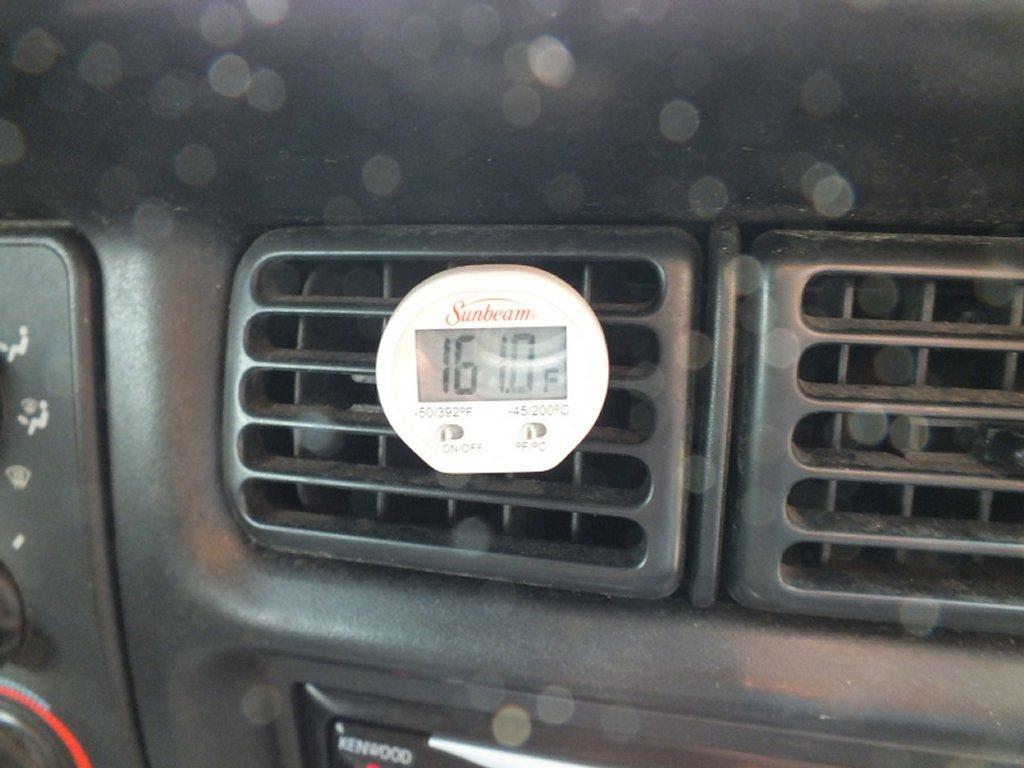
Take a digital thermometer or laser temperature gun it should measure about 150-160*F out of the center vents.
-
Sam here. I've got my shop rigged up with a garden hose and the power washer at the door so I can roll th truck outside and power washer from front to rear and bottom to top. Take notice I said bottom to top. Best to start at the bottom of the truck and then work upwards. Another trick is to lay on a creeper that way to keep you out of the water. I've taken the time to dielectric grease all my electrical to prevent water issues. So everything is far game but of course no close up and personal spraying of the connectors it will push water in even with di electric grease. I'm like TFaoro I power wash the truck as much as possibl keeping everything clean. This way its really easy to keep track of all leaks.

