outlaw7
Unpaid Member
-
Joined
-
Last visited
-
Well harness is back in my cc'd buss is working again the computers are good to go about the solder comment I guarantee they won't fail trust that for one my harness ain't riding the block no more it's away from it no need to heat soak that thing my mods are great I now have a digital led voltage display on my vp44 power feed and an in cab test ppoint for apps no more guessing my only prob is I've concluded my VP is dieying a slow death o well
-
Ok Dripley n Jag1 yes that was is the bolt and connector I'm talking about in the pic upper right corner black connector and W-T yes I fixed all of them there were 3 places the ground did that I'll be reinstalling today I'm going to open a web store selling cable kits custom harnesses test tools and DC filters stiffining solutions soon
-
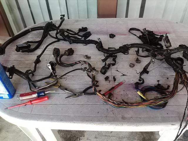
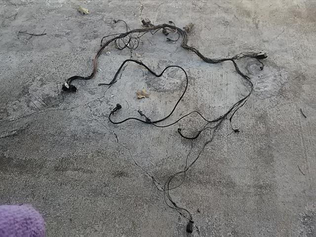
ok folks here it goes....... I found 2 grounds like w-t displayed, including one at the bottom of the ecm that had four 14awg tieed to a 10 awg that deadheads beside the starter on the block the fuel pump +12v is done this way as well as a couple buss sets and and a power set and I redid them all , I removed that big clump of orange wire that was like an extra foot and a half of uselessness, everything was fluxed soldered and heat shrunk to ease my mind.... and that's just the lower engine harness....the upper has only a couple done that way but both are bussing 2 for the +/- buss and two for the can buss protocol . yeah it was a lot of fun best part is I did not repeat not have a single short anywhere anywhen started get kinda pissy at that point. was cruising the web about my dash no bus condition and found two neat things number one is you can initiate a gauge cluster self test by holding in the trip reset and turning key to on position no start then releasing it and it will give you itws own trouble codes and everything....very cool.... and two again whilst bewildered scared and alone I found a true nugget that might save my sorry ***. guy claimed to have same symptoms I do werird codes no pcm coms no buss and dead pedaling issues that act strange he was checking connections and found his power distribution block harness connector ( the one that ties the engine harness to the firewall and power etc ) was NOT ONLY LOSE BUT NASTY HER CLEANED IT UP AND TIGHTENED IT AND BYE BYE CODES AND PROBLEMS ...WELL JUST SO HAPPENS WHEN I WENT TO YANK MINE OFF THE DAM BOLT SPUN FREELY IN MY FINGERS sorry caps lock bomb.... and as an added bonus got the green grimey goo not much but enough and it just happens to be on the buss side on the buss pins and connectors so I am going to walworld for contact cleaner cant get that keg deoxit W-T has so poor boys poor ways ive been gently scarping the female pins to clean them and then back to step hmmmm 8 so this is everything ive done all mods included step 1 remove lower engine harness, better bring your patience meter and some Tylenol 6 big pain in the keister had only two casualties 1 is my lo side ac sensor it was melted to the connector so it got the loraina bobbit treatment. 2 the ground behind the starter bolt was froze solid its 10mm and I said $%^%#$%^ and lopped it off with a note to repair it step 2 remove upper harness much mo easier guys, no problems at all total time for steps one and two 2.75 hours tools needed 10mm wrench and deep and shallows 1/4" drive , needle nose pliers flat blade screwdriver 13mm 3/8" drive and long handle wratchet side cutters and a I think 6mm allen wrench for the ecm connector step 3 clean the harness I first sprayed it with brake kleen and wiped it down then a dose of acetone on a rag step 4 strip the harnesses this was a lot of fun gently cutting and unwrapping everything and of course pictures for refrence took 1 hour and needed two pairs needle nose to spread the harness clamps open and a set of front cuts for zipties and a small razor knife step 5 reclean the harness cause it was nasty........... again acetone and a rag and patience lots of acetone and patience step 6 using a copy of the 3 illistrations for the engine bay harness courtesy of mopar1973man which I spliced together with scissors and tape to make one large continuous map for ease of use I started ohming out every last dam thing total time 3 hours on harness one with notes and 2 hours on upper harness with notes step 7 lower repairswhile I did not find any shorts I did feel the need to fix dodges sloppy handiwork so I repaired thw two ground points located just below the ecm split, the fuel pump buss also below the split and added my custom fuel pump feed for my mid frame setup as well to the ground and fuel pump, the big mass of orange wire all tied together whicg there is 18" extra nopt needed that got shortened up its listed as a switch supply at the ecm I also repaired the ground mess further up near the alternator as well as another power related one red with white stripe that was done the same way. additions were as follows....a I taped a small blue wire on to the pump 12 v+ supply for the vp44 which will go to the cab to a 12v led indicator for full time pump power notification and a orange 22awg wire to the apps sensor feed which again wikll go to the cab to a test banna point for quik check and monitor of my apps voltage via old skool analog meter these both have their own wetpack m/f connector at the point the lower ties into the upper and at the firewall where they leave going to the cab. upper the only repairs made were for the 2 can buss and the 2 buss points done the same way as the others solder and heat shrink, then I added my thermos couple feed for my gauge two 22 awg wires, 3 wires for my dc amps volts meter setup, 2 wires for the vp44 and apps test points and 4 wires 16awg for switching remotes on auxillary systems lights compressor etc, then I stripped and crimped all of my wet pack pins made an add on schematic for future refrence on pins and *** embled all my extra connectors together step 8 tapeing every 8 to 10 " for ease in relooming then adding loom and then taping the harness front to back and at at all joints total time about 5 hours tools solder iron solder sm phillips screwdriver all kinds of crimpers and strippers and other soldering based tools step 9 ohm out new additions time 15 minutes step 10 apply dielectric grease to all connectors everywhere and crimp on a new ring terminal for the ground by starter which I used 10b awg hi strand for that ground step 11 reattach the harness clamps took about 10 minutes but set them loosely cause theygotta be movable step 12 will be to install it now I removed the alternator feed because it was whimpy and I'm wantin hefty plus I'm installing my ripple filter beta test 001 for further evaluation . I'm installing 2 awg cable on its own route so that's what ive done so far
-
Well I chased all my busses out last night right into the dash and I don't have a short or anything and it's starting to piss me off I've got 7 different cuts and gouges on my hands and arms , half my truck systems on the ground grrrrrr grrrrrr. Gotta work for a church this am then starting rewrapping the harnesses while integrating some extra features , gauge wiring and test points etc gonna be a long *** night I'll post pics as I go
-
2.5 hours to remove it another hour to strip and clean it, it was nasty oil soaked and filthy . most of the flex and friction tape was garbage . the alternator feed cable is a joke for a 140 amp output unit so its going bye bye
-
That meter also comes in 750 and 1000 amp ranges as well I'm gonna work up a plug n play kit that is 52mm gauge pod based for ease of mounting
-
Well I'm scared now I'm pulling my harness this weekend for sure I got a buss bad anyway but that that's not natural
-
During my research onac ripple I came across an interesting bit in an unlikely place. The big stereo crowd has a saying called the big 3 , basicly if your gonna run a lot of amps replace the batteries cables and alternator with stouter stuff which thinking back you couldn't buy a 240 or 320 amp alternator back in 01 and you can now he'll my dad's 16 f350 has like a 240 amp alt on it just think maybe that's part of what needs done
-
Man I've got a 96 k2500 w an aftermarket alt been on since 12 it's pumping .21vac at idle it's my test bed for my filter deal and I have solved that problem but I need to prove it before I go further but it's just newer stuff in the reman world sucks and yes maybe Dodge is more sensitive idk not enough input for data
-
That's my point. Newer electronics are made in China including diodes so tolerance is ****
-
Howdy thought I'd chime in ,Jag1 the reason your having trouble soldering is the copper wire is drawing the heat away take a small gator clip and clip it on the insulation side like a heat sink in reverse also use flux and I've solved the actual ripple deal I'm just waiting on my oscilloscope to arrive for hard evidence I don't trust meters for this. As soon as I can post my proof I will and it does work I'm running a setup on my suburban right now the alt is way out spitting .21vac at idle and I'm filtering down to .0012 and I've solved the grid heater prob as well
-
$$$$$$$$$$$$
-
YES Diesel future orangeberg thaats the stuff god what deal huh?
-
outlaw7 changed their profile photo
-
best pipe ever was a tar paper wrap deal I tore it up with a snake spent two days on a shovel and replaced over a hundred feet of sewer line on not just our rent house but some other guys house that our line ran into to hit the street all in 30 degree and lower temps gotta love the 40S and their interesting plumbing moves
-
methanol keeps air lines brake chambers etc from icing over in cold temps believe me from experience it aint no fun to have a trailor or your whole rig freeze up due to ice because your preety well screwed unless you have more brakeline antifreeze or a warm shop or a shitload of patience. ive actually thawed a 30 ft dump wagon out once by preesureing up and then fanning down the brakes to the low psi warning and rebuilding psi in the tanks. it takes a while but the fresh hot compressed air from the compressor head slowly warms the system up finally my thing about your nylon airline is a... it came from an air bag kit, which ive used the same stuffits pretty cheap most of the time and b you don't really know the composition of it most of the time on the small bag kits especially and as for the dc type heat tape ....there aint no such bird........yet hmmmmmm I smell another project in the air gotta finish one before the other but how cool what that be... the other idea ive had which ive mixed feelings on is encasing the fuel line into essentially an airduct say 1 1/2" pipe thin wall and hooking to its own lil heater, problem is great in winter and temp spikes the rest of the time and who really wants to install and uninstall that every year....not me so the tape thing sounds more logical and really I wonder if of the shelf stuff like smaller lengths with less wattage might not be convertible to 12vdc or maybe a stepper power supply up to like 48 from 12vdc its real simple to do that idk have to play with it some time