
Dynamic
Unpaid Member
-
Joined
-
Last visited
Everything posted by Dynamic
-
I can't believe nobody has come up with this until now. The tuning and performance possibilities are endless if they can make it reliable.
-
Man, I would just add a good weld of equivalent size in between the ones that are already there and call it good if I already owned the flexplate. As much as I like and use the Goerend flexplate, I would not throw away that BD just because of the weld issue. But, like I said, that is assuming that the BD plate has already been used. If it were a brand new one, fresh out of the box, I would demand a properly welded piece or, more practically, send it back and buy the Goerend. I didn't know that Dave was backordered on his flexplates. I just bought one to use on Russ Roth's build last week. I must have gotten one of his last ones...
-
If I already owned it, and it has already been in service, that's what I would do. But, if I had just spent $400 on it, and pulled it out of the box only to see cracked welds, I would send it back. The problem is that the new one you would receive would likely be the same thing (after having to either wait until they received the defective one to "inspect" it and send you a new one, or buy a second one and have them refund your money for the first one when they received it...eventually). Been there, done that with them... Or, you can just buy a Goerend for less money and have it be good right out of the box.
-
The BD should be tight on the crank since it's a machined billet piece. But, if the ring gear welds are cracking (cracked), it should not be used.
-
I've never used the PRW flexplate, so I can't comment on that. There are two flexplates that I use on a regular basis. One is a "stock-style" replacement stamped steel flexplate. It is a pretty nice piece, over twice the thickness of the stock one, and less than half the price of a full billet. The other one I use quite often is the Goerend full billet plate. It is a real work of art, and does a perfect job of centering the converter hub to the crankshaft. Remember, the front of the torque converter (which also supports and locates the front of the input shaft) locates off of the center bore of the flexplate, not off of the crankshaft as is the case in many other applications. The more precise you can be in locating the flexplate to the crank hub, the more precise the location of the front of the converter (and, thus, the input shaft) will be. Goerend is as good as they get.
-
I always reuse it. Like I mentioned in the other thread, check the weld that hold the ring gear on. I won't use BD flexplates anymore because of cracked welds and BD's not-so-helpful attitude about the whole thing.
-
The 100 hz signal is not an AC signal. It is a pulse width modulated DC signal running at 100 hz. A PWM signal allows them to vary the field current to the alternator, controlling its output. The relay is wired into this system so that there is no power to the transmission unless the alternator is charging (aka engine running).
-
For stock (or near stock) power levels, I would definitely recommend my Stage 2 build, with a Stage 3 billet triple disc torque converter. This is, by far, the most common setup that leaves my shop. I will run this setup up to about 400 hp. Here is what is included in the Stage 2 build: STAGE 2 47RE · 5 disc direct clutch (full thickness Borg Warner frictions/Raybestos full thickness steels) · 4 disc forward clutch (full thickness Borg Warner high energy frictions/Raybestos full thickness steels) · 6 disc OD direct clutch (full thickness Borg Warner high energy frictions/Raybestos full thickness steels) · 10 disc OD direct clutch (stock setup) · Raybestos Pro Series intermediate band · Sonnax billet intermediate servo cover (w/pin o-ring) · Sonnax billet dual seal accumulator piston (scarf cut Teflon/D-ring at each end) · Sonnax billet low/reverse servo piston · Superior reinforced band strut · Heavy duty Borg Warner low roller clutch · Heavy duty Borg Warner OD roller clutch · Low roller clutch direct lube modification · OD brake clutch cooling/lube modification · Forward clutch diaphragm spring · Complete OD thrust bearing set (w/updated sun gear thrust plate) · OD output ball bearing · Dimpled bronze pump bushing · Heavy duty direct drum bushing · OEM OD/TCC solenoid set (w/internal harness and case connector) · Custom calibrated valve body features: o Full cooler flow/converter charge in park o Increased line pressure o Modified TV pressure and curve o Full time lube modification o Custom shift calibrations (tailored to customer’s usage and preferences) o Modified to allow 3-4 and 4-3 locked shifts (external switch required) Optional: 1st/2nd gear lockup ability (external switch required)
-
Do you have any specific questions? I'd be happy to discuss your transmission with you...
-
Not sure about the drag strip just yet, but it does run pretty good! Now I just need to concentrate on getting this transmission to shift well. I haven't done anything to it yet, but it's time! The gear ratios are great and work well with the Hemi, but the shifts...not so much! Time to come up with some valve body calibrations that work.
-
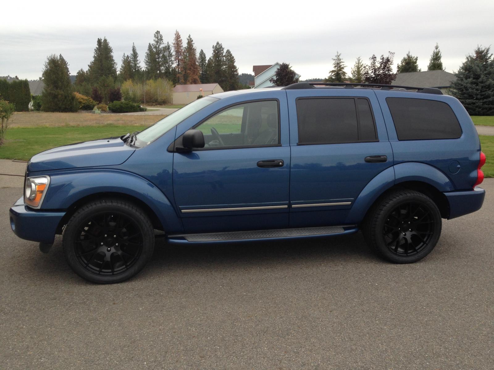
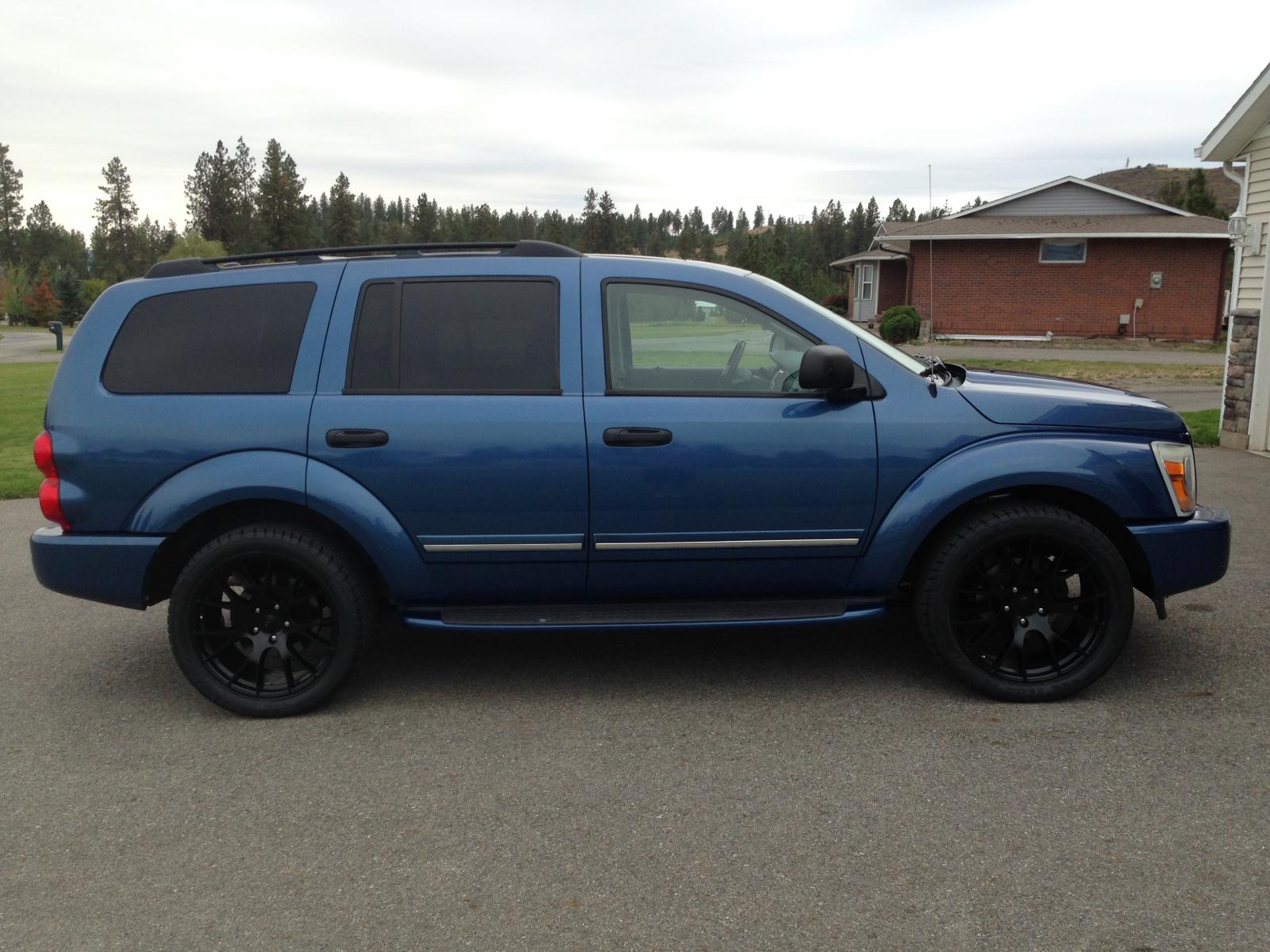
Well, I finally got Project Hemi on the road. It's got about 300 miles on it now, and I'm zeroing in on the final tuning of the engine. It definitely runs good, that's for sure. I spent some time yesterday getting the rear ride height where I wanted it. I ended up lowering it exactly one inch. I may go another 1/2" or so, but it definitely looks better now than it did. The wheels and tires I put on it are a little larger in diameter, and whole lot wider than the stock size, so they fill out the wheel openings better. Here are some pics...
-
I knew that was coming... LOL Soon...!
-
Got the engine installed and running. It fired right up...perfect oil pressure, no leaks, cooling system bled right out, valve train silenced itself after a couple of minutes to pump the lifters; no mechanical issues to speak of. Everything as expected. I do have some tuning issues to deal with, though. The factory programming isn't working real well with the larger 6.4L fuel injectors, and the considerably larger camshaft. Nothing a little time with HP Tuners and a pair of wideband O2 sensors won't fix. Even with the poor fuel and timing maps, running quite rich at the bottom, and extremely lean up top, this thing has some muscle...! Traction control and AWD might come in handy should I somehow, by some strange happenstance, find myself at a drag strip someday. Up next: tuning and exhaust system...
-
Haha... Yeah, it's a pretty wide engine, and it's pretty tight getting it in and out of there, but it DOES fit...
-
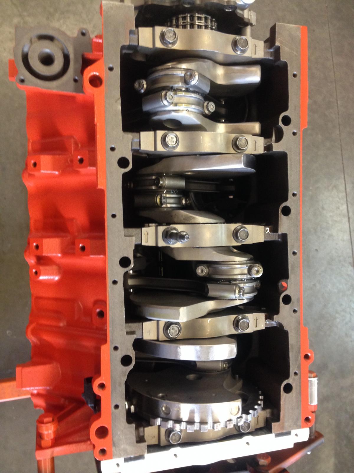
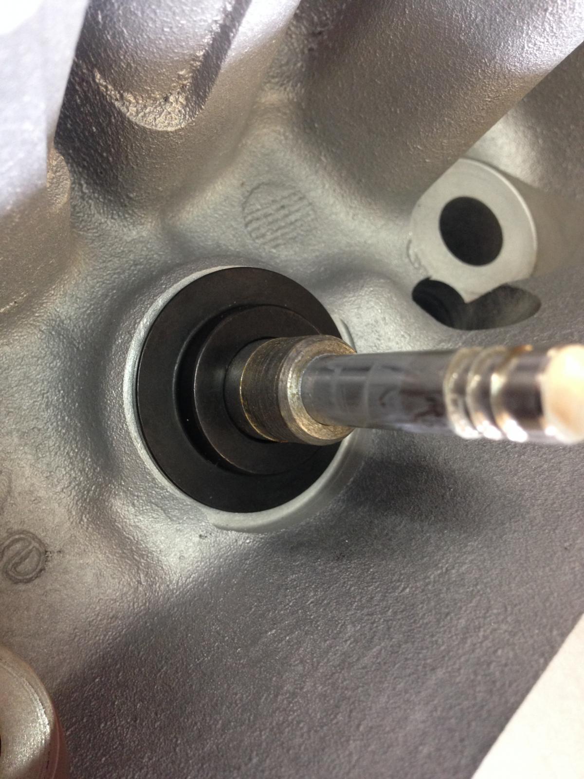
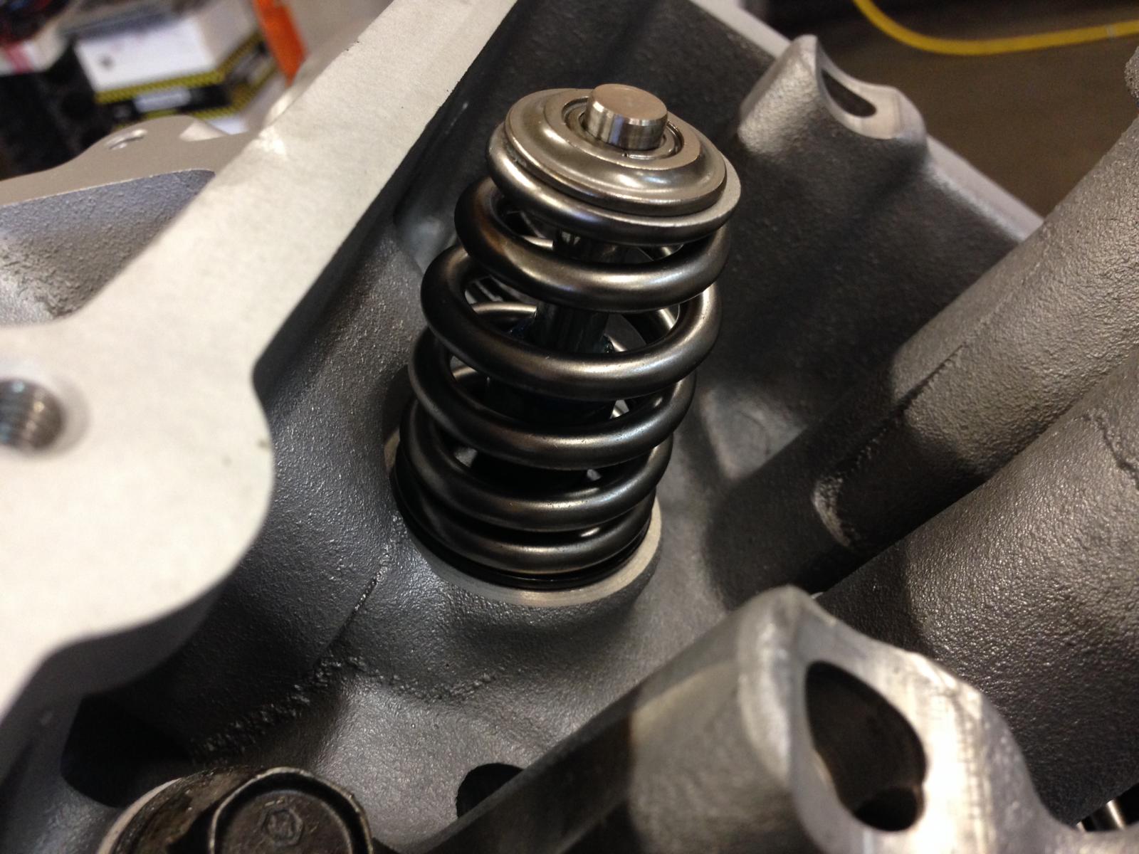
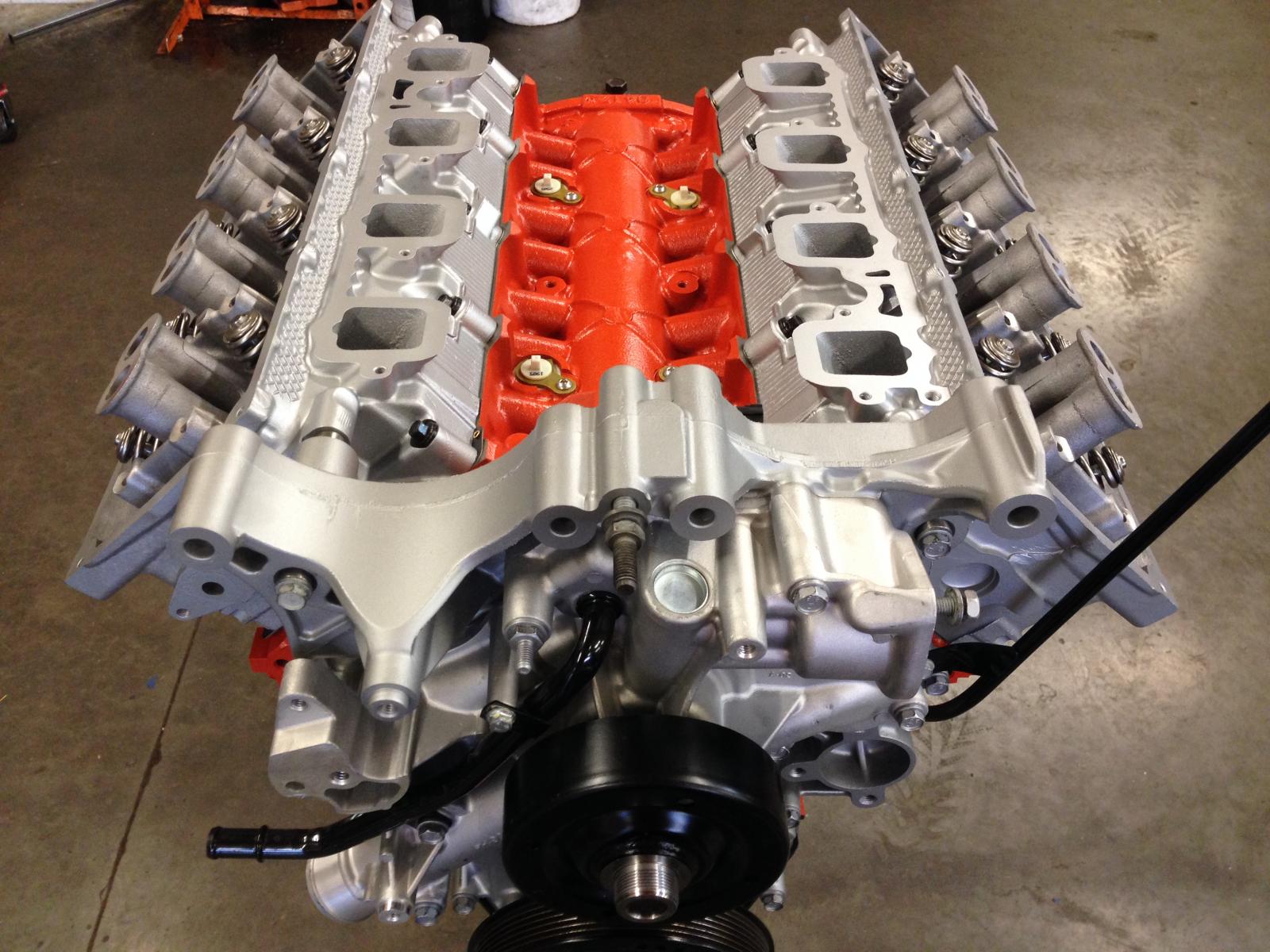
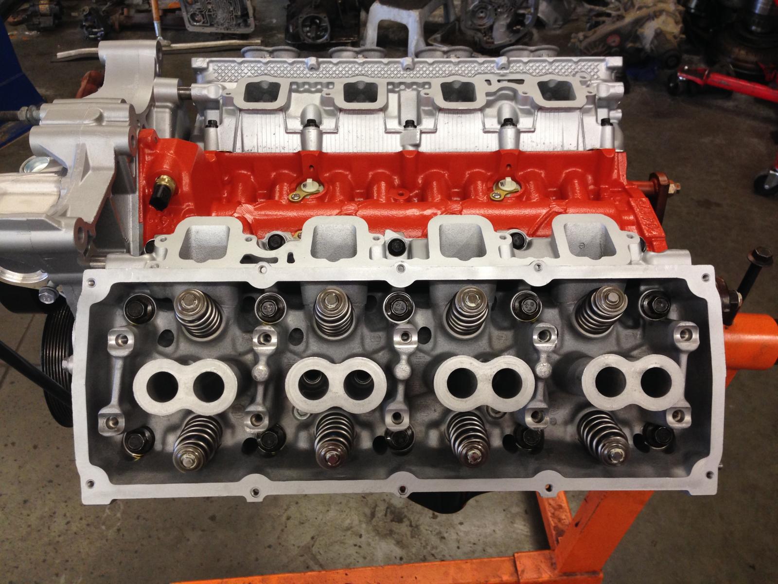
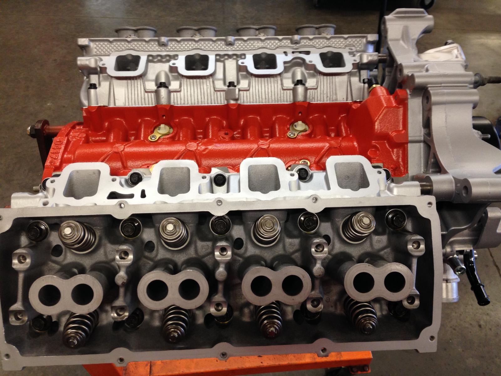
Well, it has been a busy summer. Lots of family trips, a lot of transmissions built, a lot of music played, a lot of outings on the boat, etc... Progress on the Hemi has been slow, but I have managed to get it just about finished. The custom thickness head gaskets arrived from Cometic, the new head bolts came in, the heads final assembled with the stainless 6.1L valves and PSI LS1511 valve springs, and now the heads are torqued on permanently. The bottom end is all together, and its new oil pan installed (the original pan was destroyed by an angry connecting rod). I'm just waiting on rocker shaft collars from Stanke Motorsports (top shelf stuff for Hemis...), and then I can assemble the rocker shafts and final assemble the valve train. I was afraid that I would have to use expensive custom-length pushrods with all of the block decking and head shaving that went on, plus the smaller base circle of the custom-ground camshaft. But, after mocking everything up and measuring pushrod lengths, I found that stock length 6.1L pushrods work perfectly, and give about .060"-.065" of lifter preload...perfect! Manley makes a nice set with those lengths, so that's what I will be using. It's the same set that I used on my other Hemi... Here are a few pics... A shot of the bottom end before the oil pan went on. On the Hemi engine, the oil pan gasket incorporates the windage tray to help control...well, windage. Because of the much longer stroke of this setup, I used an OEM 6.4L pan gasket (mucho $$$, by the way...). The 6.4L gasket has some extra reliefs in it to accommodate the longer stroke of the factory 6.4L crankshaft. This made it easier to clearance everything so that there were no interference issues. I only had to tweak a couple of spots. No big deal... Here's a pic of the GM LS engine lower spring locators I used to stabilize the bottom of the valve springs. Valve spring breakage is a known issue with the Hemi engines and engine builders tend to agree that aside from poor quality OEM springs, the lack of good locators on the bottom of the spring is to blame. This is my solution... Aside from the extremely high quality springs from PSI, I machined the top of the guide down .018" so that I could use these Comp Cams locators. There is also a .015" shim under each locator to bring the valve spring installed height to exactly 1.800". And here are a couple of pics with the heads final installed, as well as the timing cover, balancer/crank pulley and water pump. Cheers...!
-
An empty stock 47RE/48RE system holds 16 qts, an empty stock 4R100 system holds 17 qts.
-
Yes, like Mike said, loosen the VB bolts enough to separate it from the case a crack and then wait for it to stop dripping. This will allow the converter to drain back (to the level of its hub, anyway). You'll get an extra 3 qts out of it or so. Don't forget to retighten the VB to the case (105 in/lb), and then proceed as normal, but remember that you'll need an additional 3(ish) quarts of fluid after all is said and done.
-
10-12 ft/lbs should be fine. I usually just hand tighten them with a speed handle.
-
Back off the adjuster jam nut, tighten the adjuster down to 72 in/lbs (NOT 72 ft/lbs...!!); 72 in/lbs is equal to 6 ft/lbs. This seats the band. Now back off the recommended number of turns on the adjuster, and lock the jam nut back down. Done... The number of turns to back off the adjuster depends upon a number of things, but I typically run mine at 1-3/4 to 1-7/8 turns.
-
MDS plugs in the block. Tuning... Haha... If only things worked that way! It would be a heck of a camshaft to get a stock 5.7 Durango to 450 hp! But, if it did, it would be in some pretty ideal conditions. But, assuming that you did find that magic camshaft that brought you to 450 in an otherwise stock 5.7 with a Durango intake and exhaust (which I highly doubt), the extra displacement of the 6.4L (392) certainly isn't bringing another 150 horsepower to the table; more like 35-40, with an ideal intake and exhaust situation. Same with head porting; just a few more hp is all... Believe me, I'm in the process of building one, so I'd love nothing more than for you to be right! LOL But, I think you're about 100 hp or more on the optomistic side.
-
Yours is an '07. You don't have VVT. You likely DO have MDS (Multiple Displacement System), though. Larger cam grinds don't usually play nice with MDS. It's easier to eliminate it. 600 hp is a pretty tall order for any naturally aspirated, streetable setup. With my setup, I'd be happy if I hit the 500 hp mark, but high 400's is realistic. Big hp numbers don't come easy.
-
Nice ride... It sounds like you have some decisions to make. If you want a 5.7 based 392, I would not hesitate to recommend the parts that I used. The one big decision you'll have to make, though, is whether or not you're going to run a supercharger because that will drastically affect the compression ratio you spec out for your build. With the pistons that I used, and the chamber size in the heads, my compression ratio is about 10.8:1. This would be quite high for a supercharged application. I would shoot for closer to 8.5:1 - 9.0:1 if I were going to supercharge mine. The lower the compression, the more boost you can run. I don't believe the '07 Hemis used VVT, so camshaft specs should be easy. If you want that idle chop, you're going to want something in the high 220's or low 230's on both sides (duration at .050") on tighter lobe centers. This will maximize valve overlap, which gives that idle lope. But, it also drastically complicates tuning. Early 5.7 Hemi heads are happy in the .550"-.580" lift range, plus then you can get valve springs that work well and are affordable. I am using PSI LS1511 springs (which are a GM LS valve spring) on mine. My lift is .575"/.585". The other thing about camshafts is that a grind that is spec'd out for a supercharger is going to look quite a bit different than one spec'd for a naturally aspirated engine. I'm a big believer in custom ground camshafts. Get exactly what you want, not an off-the-shelf compromise... As far as headers go, I haven't tried any yet, but there are a couple of Ram 1500 P/U long tube header sets that look like they may fit. It's a tight squeeze on a Durango/Aspen, especially on the driver's side, but I think the Dynatech headers may work. I'm basically a header snob, and only recommend stainless steel long tube headers. In my opinion, shorty headers are not worth the hassle. You still have to reconfigure the front part of your exhaust system to get them to connect to the rest of the exhaust system, and most offer little gain over the stock manifolds. Stainless looks good, last longer, and won't rust like mild steel headers will.
-
I'll get some more pics uploaded soon. I have the bottom end put together, and waiting for head gaskets (which I had to have custom made). Long story short, everything went together great! All clearances came out basically perfect; no issues there. When you use good parts and have good machine work done, final assembly is generally a non-issue... Chad, welcome to the forum. What questions do you have about building the Hemi? I've been building engines for about as long as I've built transmissions (about 28 years), and have done several of the late-model Hemi builds I generally try something different every time. This one has been my most "exotic" one yet, if you can call it that. One thing that I will tell you off the bat is to plan on getting a decent set of rods. The stock rods are VERY weak pieces, and are the reason that many of these things end up in the wrecking yard...
-
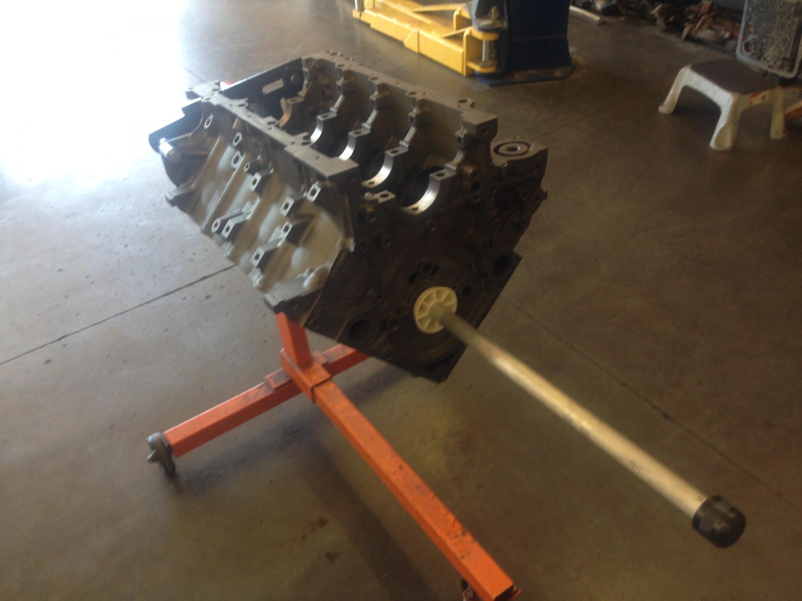
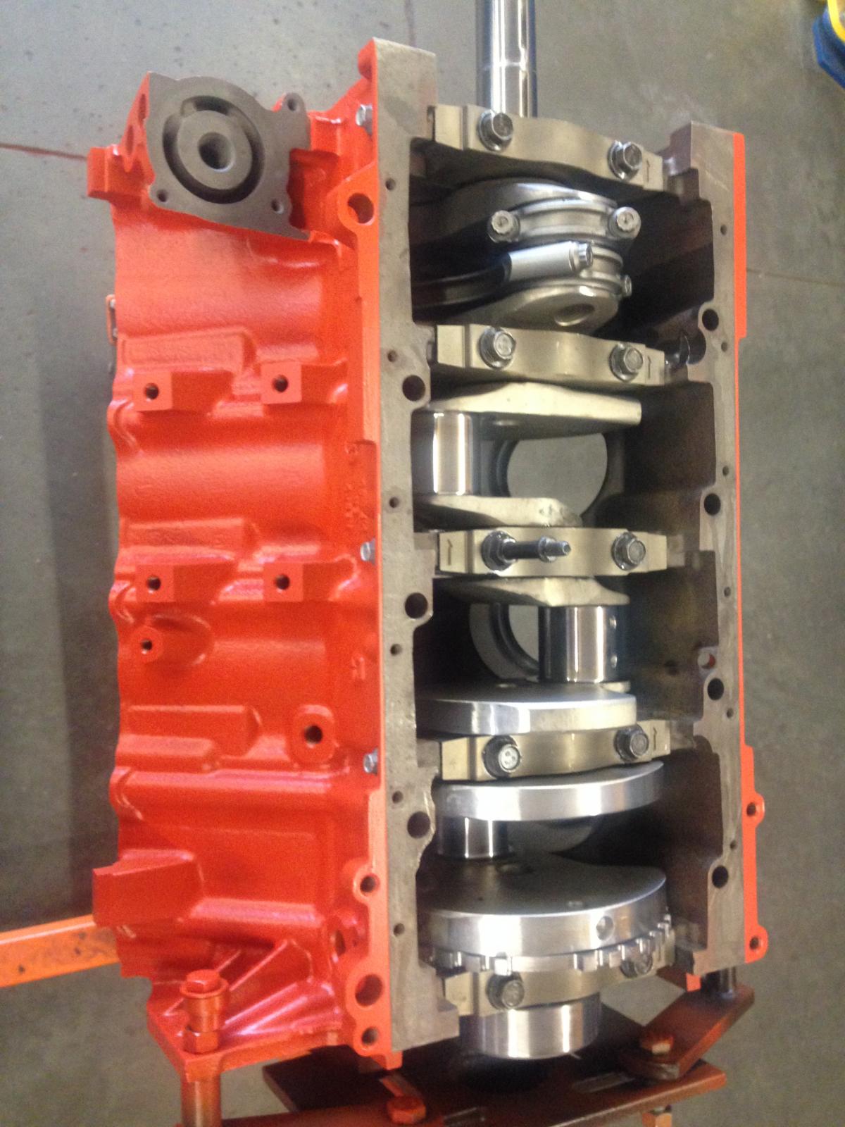
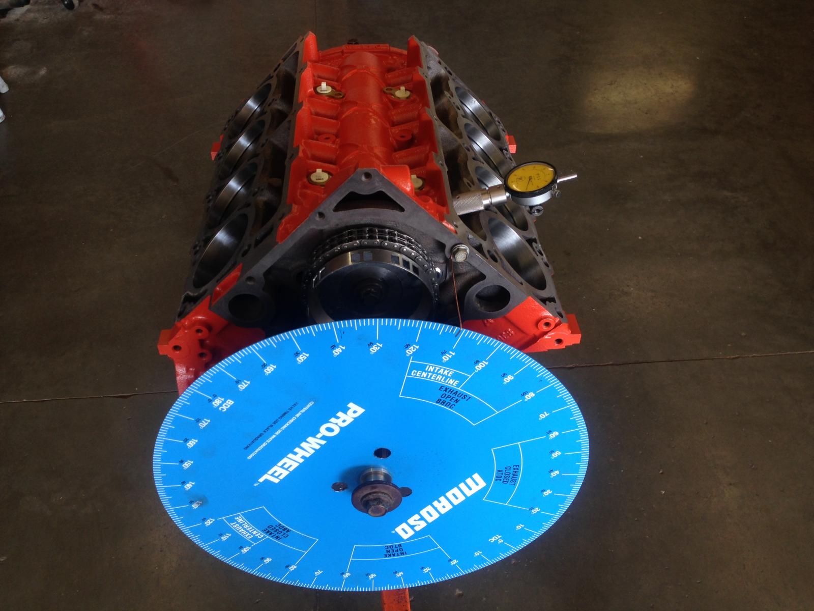
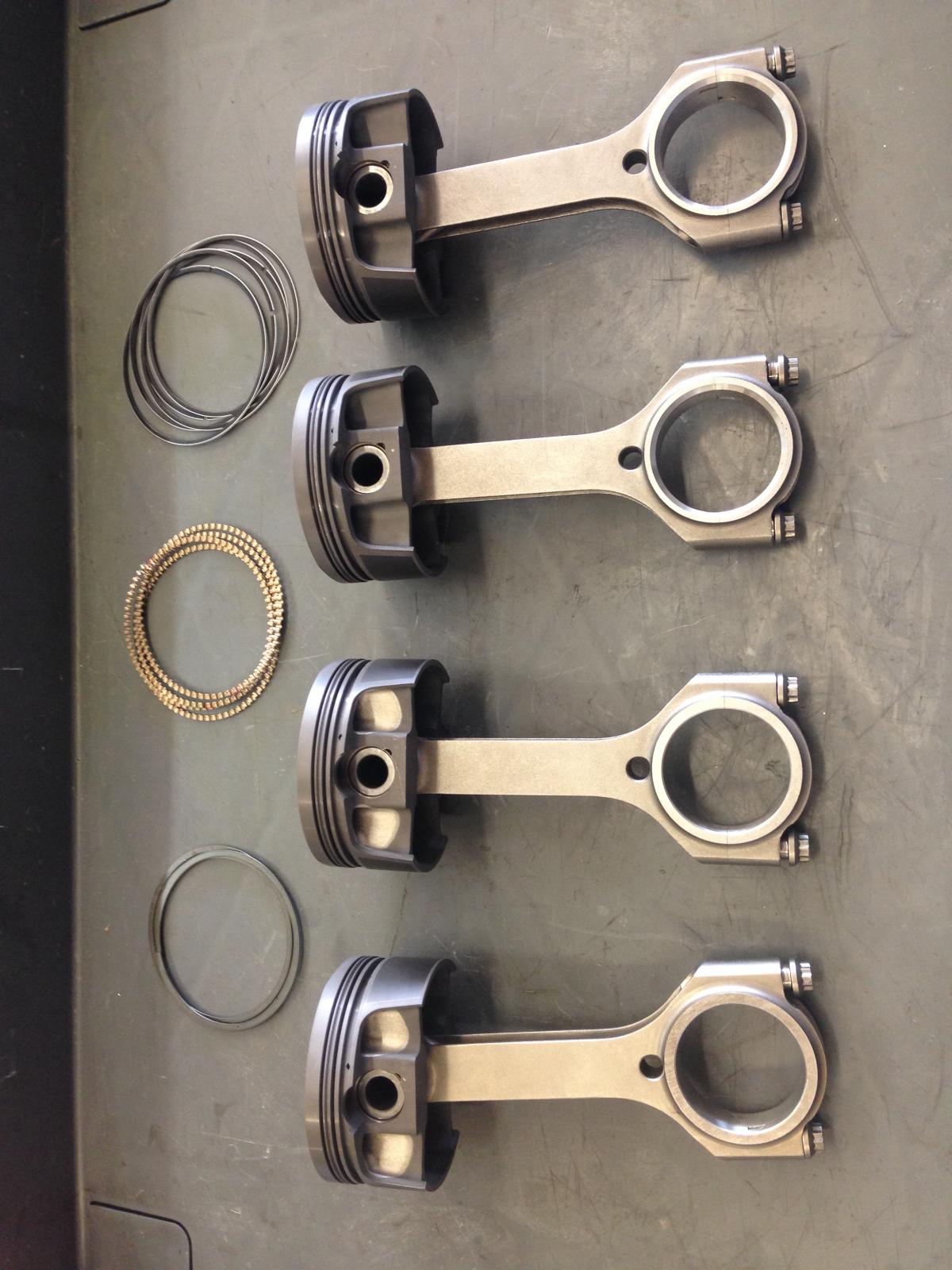
Finally making some progress on the Hem build. All of the machine work is finally finished, and I can start going together with it. After a thorough cleaning of the block, and scrubbing the bores with hot soapy water to remove all of the honing abrasive, the next step was to install the cam bearings. After filing all of the rings for the proper end gap, the pistons were hung on the rods for final assembly. Filing ring gaps is a tedious, iterative process, but one of the more important steps. Most ring sets anymore come "oversize" so that the ring gaps can be set where the builder wants them. I set mine at .018" for the top ring, and .020" for the second ring (for those scoring at home...). Here are some of the pistons, hung on the rods, ready to install... After a few coats of Chrysler Hemi Orange paint, the crankshaft went in for the final time, as well as the front two pistons and rods (#1 and #2) in order to degree the camshaft. I like to degree the camshaft with as few pistons installed as possible because the less drag there is, the easier it is to be ultra-precise in the degreeing process. You obviously need #1 to establish TDC on the degree wheel, but I always like to install the other piston/rod that rides on the same crank journal to keep the rod from floating around side-to-side. It's a minor thing, but it's just my way... Here's the block with the crank and front two pistons/rods final installed... Degreeing the camshaft is also one of the more important steps in any engine build. The cam was spec'd out and ground to be in a specific relationship to the crankshaft. The process of degreeing the cam ensures that when it is installed, this relationship is, in fact, correct. I had this camshaft custom ground with 115 degree lobe centers (the number of degrees between the center of lift of the exhaust lobe, and the center of lift of the intake lobe). I wanted to run this camshaft with the intake centerline aligned at 112 degrees ATDC (after top dead center) of crank rotation on the intake stroke. That is the center of intake lift (intake valve all the way open) occurs at 112 degrees ATDC. This is all done with a degree wheel and a dial indicator riding on the #1 intake lobe of the camshaft. Here is that setup... Now, on to installing all of the other pistons, and assembling and installing the heads. (I had to order custom thickness head gaskets in order to get my quench set where I wanted it. Long story... I'm still waiting on those.)
-
Yes, I can service your transmission. I'd have to look at my schedule, though. I'm pretty steadily booked until the middle of July right now. It can be a little tricky to schedule a service when I've got full builds filling out the schedule, but I can make it work. What kind of tune up stuff are you looking for?