

W-T
Yearly Subscription
-
Joined
-
Last visited
Everything posted by W-T
-
Very sorry to hear this, be well. W-T
-
@LD-Ordie I have a Smarty and I also return to stock settings every two years for the Smog check. Once the Smarty is hooked up I always clear the "over boost" code because the Smarty fuels passed the 20 psi limit of Factory programing. I also return to "stock tire size" because I'm rolling on 37" tires. I don't have any other codes and once you return to Stock Factory spec's your Smarty leaves no foot print of being involved with programing. That feature was specifically engineered by Marco in Italy over 20 years ago. It works flawlessly and I have never experienced an error in 20 plus years. NOW...as for you stacking an Edge product with the Smarty, I do not know why you would do such a thing, are you also removing the Edge device and allowing the Smarty to clear what ever mess that leaves behind? If so, do you see a clean report from your Smarty once you clear everything? The Smarty will clear codes completely but, if you have an error and a code returns after clearing it with your Smarty...you have homework to do. I'm not scolding you but, stacking programmers is so hayseed lame. Get a Quadzilla and do to it right, you won't regret that. (I love spending other peoples money) If you do not have any errors, your Smarty will clear standing codes and you can roll into your Smog inspection station with NO fear. Respectfully, W-T
-
Yeah...me too, I was under the passenger side the other day and I found a spot of dirt so I freaked out, ran to get some Q-tips and a tooth brush to fix it! Boy, am I glad I found that, I would have been mortified if someone had seen that...I was just lucky to have found it before anything had gone wrong!
-
These lift pumps we are referring to, are all mechanical Cavity Gear pumps. Most all of us, are familiar with this design and the history in the automotive industry exceeds 50 years or more. Yes, as John @Tractorman has pointed out these are positive displacement pumps and by design they are modest in their ability to manipulate liquid material in a closed environment. This environment has restrictive characteristics at both inlet (feed point) and outlet (discharge) aspects, that in design, these pumps can over come these resistive road blocks and deliver diesel fuel reasonably well. However ; the term "reasonably well" has limits due to the modest nature of these Cavity Gear pumps. These little pumps are great for the purpose they were designed for but....do not expect them to operate in a poorly designed or maintained transfer system. The ability to draw liquid diesel fuel with these wimpy little pumps requires a clean low restriction feed method,...meaning NO Oatmeal in the screen basket within the fuel tank. I know...everyone knows this...but, if you can't see your wetted-feed point within the tank, I would suggest inspecting that aspect. Any minor air leak that may not be evident in a cold environment may very well become apparent once the environment changes thermally. Usually fittings with a mated surface for point to point surface contact will prevent liquid seepage but, this same fitting could suck-air and hinder pump operation once the thermal threshold has been met and exacerbates the expansion/contraction coefficient of the metal components in service. Air is easier to suck through a straw compared to a milkshake so, the effort to find an elusive air-leak that is so incredibly tiny is a challenge. Avoid the "just tighten the crap out of the fitting" method. Always apply light lubrication to the "mated fitting's" surfaces, prior to mating them and avoid galling the jeweled surfaces. @Basranabread I'm only trying for a simple solution, and I appreciate your diligence along with excellent commentary and it is your information that leads me back to the primary observations. It causes me to suspect an air leak. The condition within your fuel tank that can't be seen for verification would be a resistive element. Going back to the modest design of these pumps and how small errors will lead to faulty performance, it is just the nature of this particular design. The system design is providing liquid pressure maximums of 15 to 20 PSI and these characteristics place this style of pump into the "Peanut Whistle" category where very small leakage errors cripple the performance drastically. Your observation of "noisy pump" and once re-primed....goes quiet....tells me it's sucking air. Oh...yeah, what O-ring?....you're scaring me when you placed that into the "what if " equation. Respectfully, W-T
-
@jlwelding what @LorenShas shared here is correct...to be fully accurate, I too, did the same with the Carter lift-pump bracket. The small block Chevy block off plate I purchased from NAPA was my choice however; once I removed the "dog legged" bracket of the old lift pump, it was easy to see only a slight cut-off trim job was required to create a clean fitment. I returned my Chevy block-off plate and utilized the return to purchase a can of spray paint. Gosh...I guess my old memory is beginning to fail...Loren, thanks for correcting this aspect, why spend the funds when the block-off element is available to accomplish the task.
-
It's an excellent modification to clean up that area of the engine compartment. You'll find the chrome-plated mechanical fuel pump "block-off-plate" available at nearly every auto part store or on-line source. I have done this myself and it's very easy to perform, plus it looks better. I think I spent $6 at NAPA (years back) and it includes the gasket. Yep...my bad, I should have noted @dieselautopower first, they have all the cool stuff !
-
I carefully reviewed my post for spilling errors before I posted I kneed to be a bit more kareful.
-
@Andyba20 The ambient temperature is measured by the IAT to allow the ECM to adjust perimeters for proper engine running conditions. The battery temperature sensor on the drivers side is the element that determines charge rate. The thermal change or stress to the battery case is provided to the PCM via this particular sensor to limit the amount of current generated by the alternator. The "two" batteries being less than 4 months old...disconnect the adjoining cables and with your DVM verify both batteries are equal in static DC potential. Each battery should reflect nearly identical voltage levels. One may show 12.6 volts the other may show 12.5 volts and this is acceptable. If you have one storage cell at 12.2 (just approximate) and the other is 11.5 volts (as an example) this indicates a damaged cell within the battery that is showing 11.5 volts. This damaged cell will continually draw current from the healthy battery and this discharge will pull the 'head charge" off the healthy storage cell in this parallel configuration. NOTE: All storage cells are static at 12.6 volts. Anything less than 12.6 is considered discharged and requires replenishment via the charging system. Ground is so very important especially in "high current" generation systems. Please examine your alternator's mechanical mounting system. The case of the alternator is the main ground reference for your diode stack within the alternator. The PCM controls the charge as Mike @Mopar1973Man has pointed out utilizing the "green wire" from the PCM as a variable "ground reference" to vary the amount of current being generated. If the integrity of the ground between the alternator's case structure is compromised the PCM can not track charge rate correctly. Under high current demand (operating a wench) for extended periods of time all connections of the parallel configuration must remain cool to touch. Any notable thermal variation between separated terminals when conducting high current demand is an indication of poor continuity at the terminal where you note the higher temperature. Tractorman's contribution here needs to be considered Biblical, especially when sinking current loads of 100 amps or more! The batteries individually, have a CCA (cold cranking amps) most likely exceeding 750 Amps each and in parallel this accumulates to 1,500 Amps. This is substantial and total energy available (Ohm's Law) 12.6 volts X 1,500 Amps = 18,900 Watts of energy. The highest current demand these CTD's see on a regular basis is the starter motor when activated to start the engine. Current demand can approach 700+ Amps but, this demand, under normal conditions, occurs for a short period of time and the system is well designed to perform this duty. The wench device is another high current demand device. The operation exceeds the intermittent time of the starter motor at half the current demand but, 280 to 300 Amps is a large demand to supply for a period of 5 minuets. The robust condition of your system is put to the test in this scenario and should be closely inspected. This "wench" device needs to be checked in a simple static spin TEST to verify the integrity of the field windings. 1) Divorce the DC motor from the drive mechanism 2) Hand spin the armature to verify "free spin" without binding, it should feel uniform through a full 360' degrees of rotation. 3) Take a test-lead with alligator clips on each end and attach the alligator clips to the DC terminals on the motor, you are shorting the brush contacts on the armature that connect to the field windings of the DC motor. 4) Holding the motor steady, begin hand-turning the shaft, you will feel substantial resistance as you attempt to turn the armature a full 360 degrees of rotation. You are feeling the electromagnetic self-generation within the armature structure and it will resist your turning the shaft through the "entire" 360 degrees of rotation. You must NOT feel a loose spot! It resists you turning the full 360 degrees with very uniform physical resistance! If, as you turn the shaft (DC terminals are shorted together with the test lead) and you feel a "loose spot" where it "slips" easily as you turn at a very particular location on the armature's brush location, this indicates a shorted field within the windings. This is a bad motor winding of the wench's motor. All DC motors can be examined for proper integrity in this poor-mans test procedure. It is a fast and accurate method to determine if an armature is shorted to it's adjoining contact, or, a field winding has shorted and is drawing excessive (massive) current as the armature spins the 360 degrees of rotation. Rich Man's procedure. 1) Procure a 1.5 volt battery (AAA or AA or C cell) or D cell, do not use a full size 12 Volt auto battery. This test requires a very low voltage and current supply. 2) Two alligator test leads are required. 3) Carefully hook the test leads up to the battery + to plus and - to minus 4) Attach the ground first to the motor, then "as you hold the battery in your hand" connect the + lead to the motor. The low voltage (1.5 volts) will spin the motor "very slowly" in operation, be sure to allow the motor to spin a full 360 degrees. PAY ATTENTION ! If, as you low-voltage, rotate the motor and it comes to a STOP, the battery in your hand will get very hot QUICKLY! This is the "bad spot" on the armature, QUICKLY remove the battery voltage from the motor. The battery will get hot so fast, along with the test-leads, a technician will know immediately to terminate the test...he has found the dead-spot within the motor. A) low voltage test just "tickles" the field windings and the motor spins slowly to it's point of ERROR. B) the low current supply of the battery will not cause additional damage or fire in the controlled test-procedure. C) key aspect, low voltage reveals the error quickly. Review, a "load" or DC motor spinning at a standard rate of speed, being supplied a huge amount of current (parallel DC storage cells) will "spin passed" the dead spot but, every rotation encounters the dead spot and at that very moment it sinks excessive current that is dissipated in the form of heat and NOT kinetic energy of motion. This is an extreme loss of efficiency and will pull the head charge off storage cells quickly. Your procedure of operating a wench is correct, timed operation and rest periods between "grunt" effort and the CTD at idle should allow this to function correctly. The timing sequence of operation you posted, along with the "quick" low voltage warnings cause me to encourage your examination of each connection (thermal change) the alternators ground integrity (the physical mounting) and the condition of your wench motor's armature/field windings. Be sure the drivers side battery temperature sensor is firmly in the baby's butt. W-T
-
Hydrogen...yeah it's flammable ! DO NOT DO THIS...... here, hold my beer and watch this. Find a Coke bottle, 16 Oz or 12 Oz Measure out one tablespoon of Draino (ask your wife, it's under the kitchen sink) Put the powdered Draino into the Coke bottle Find the aluminum foil (ask your wife, it's in the drawer in the kitchen) Take a piece of aluminum foil and with a scissors, cut up a bunch of little tiny strips no wider than 3/16's of an inch wide, 1/2 inch in length (you are making a little pile of aluminum foil...no more than a tablespoon full. Pour the shredded aluminum into the bottle with the Draino Go find a balloon or an unused Condom....( had to put this instruction in because Mike Nelson might do this and the Condom must be unused) Measure out about 6 to 8 Oz's of cold tap water. Carefully, add the water to the bottle...it will react IMMEDIATELY....it will get HOT FAST! Put the balloon over the lips of the bottle...it will "gas off" and fill the balloon (or Condom) CAUTION.... you now have Hydrogen Gas....do not do this while smoking a blunt.... Now...hand me my beer back. Again... DON'T DO THIS...it is dangerous but, damn fun! W-T
-
TACHOMETER DESCRIPTION A tachometer is standard equipment on all instrument clusters. The tachometer is located just to the left of the speedometer near the center of the instru- 8J - 30 INSTRUMENT CLUSTER BR/BE SHIFT INDICATOR (TRANSFER CASE) (Continued) ment cluster. The tachometer consists of a movable gauge needle or pointer controlled by the instrument cluster circuitry and a fixed 210 degree scale on the gauge dial face that reads left-to-right either from 0 to 6 for gasoline engines, or from 0 to 4 for diesel engines. The text “RPM X 1000” imprinted on the cluster overlay directly below the hub of the tachometer needle identifies that each number on the tachometer scale is to be multiplied times 1000 rpm. The gauge scale of the gasoline engine tachometer is red lined at 5000 rpm, while the diesel engine tachometer is red lined at 3375 rpm. The diesel engine tachometer also includes text that specifies “DIESEL FUEL ONLY” located just above the hub of the tachometer needle. The tachometer graphics are white and red against a black field, making them clearly visible within the instrument cluster in daylight. When illuminated from behind by the panel lamps dimmer controlled cluster illumination lighting with the exterior lamps turned On, the white graphics appear blue-green, while the red graphics still appear red. The orange gauge needle is internally illuminated. Gauge illumination is provided by replaceable incandescent bulb and bulb holder units located on the instrument cluster electronic circuit board. The tachometer is serviced as a unit with the instrument cluster. OPERATION The tachometer gives an indication to the vehicle operator of the engine speed. This gauge is controlled by the instrument cluster circuit board based upon the cluster programming and electronic messages received by the cluster from the Powertrain Control Module (PCM) over the Chrysler Collision Detection (CCD) data bus. The tachometer is an air core magnetic unit that receives battery current on the instrument cluster electronic circuit board through the fused ignition switch output (st-run) circuit whenever the ignition switch is in the On or Start positions. The cluster is programmed to move the gauge needle back to the low end of the scale after the ignition switch is turned to the Off position. The instrument cluster circuitry controls the gauge needle position and provides the following features: ² Message Failure - If the cluster fails to receive an engine speed message, it will hold the gauge needle at the last indication for about four seconds, or until the ignition switch is turned to the Off position, whichever occurs first. If a new engine speed message is not received after about four seconds, the gauge needle will return to the far left (low) end of the scale. ² Actuator Test - Each time the cluster is put through the actuator test, the gauge needle will be swept to several calibration points on the gauge scale in a prescribed sequence in order to confirm the functionality of the gauge and the cluster control circuitry. The PCM continually monitors the crankshaft position sensor to determine the engine speed, then sends the proper engine speed messages to the instrument cluster. For further diagnosis of the tachometer or the instrument cluster circuitry that controls the gauge, (Refer to 8 - ELECTRICAL/INSTRUMENT CLUSTER - DIAGNOSIS AND TESTING). For proper diagnosis of the crankshaft position sensor, the PCM, the CCD data bus, or the message inputs to the instrument cluster that control the tachometer, a DRBIIIt scan tool is required. Refer to the appropriate diagnostic information. This information is from the FSM section 8J - 31 Instrument Cluster TACHOMETER. From your description and the conditions being momentarily non-functional, I'm going to guess this is an intermittent error. I'd suspect dirty contacts at connection point(s) to begin with. Remove the multi-pin connectors at the PCM fluid flush the connectors with WD-40 and purge with compressed air. WD-40 works very well as a cleaner. This system is entirely electronic in design and 20 plus years of "under the hood" conditions along with lead-acid batteries fuming sulfuric acid gasses can lead to contamination of low current sensing circuits. I'd be interested in knowing what you discover? W-T
-
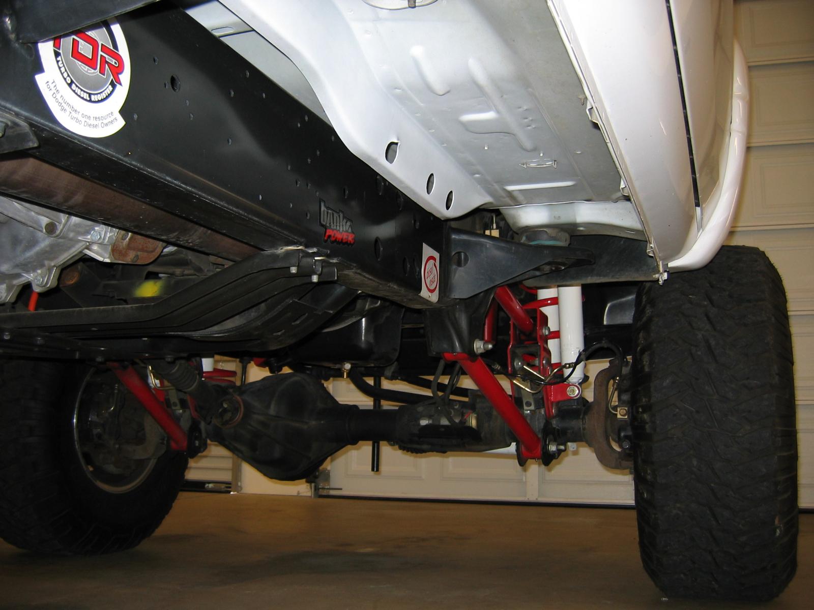
@Doubletrouble you're correct, this truck has accumulated less than 3000 miles since 2009. It was parked in the garage and driven on weekends just to show it off. The 2000 square foot garage was constructed specifically for this CTD and was environmentally controlled...to this day, when you open the door to the cab, the interior is immaculate and the smell of the leather reminds one's senses of a new vehicle. As a hobbyist in the CTD 2nd Gen Cult club, I prefer to tinker all day long and NOT get my hands dirty. Most diesel enthusiasts find my insanity appealing...the sub chassis has the equivalent appearance too. @LorenS sharp Eagle-eye...that L-fitting (JIC) is what AirDog would provide with the "installation kit" to pick off fuel pressure delivery from the lift pump. A short quality rubber line delivers the fuel to a diaphragm isolator on the firewall. I use 50/50 antifreeze plumbed to the internal Fuel pressure gauge in the cab. The photo is deceiving due to angle and lighting. I was mostly concerned about @Timburrr and how he was rewiring his DC, I wish his efforts to be successful without error. W-T
.jpg.da76d0ddfaa625d5ad38d1cf9befce37.jpg)
-
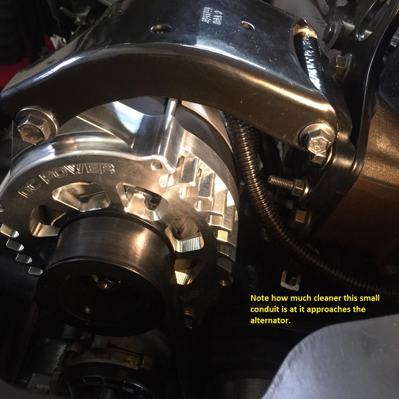
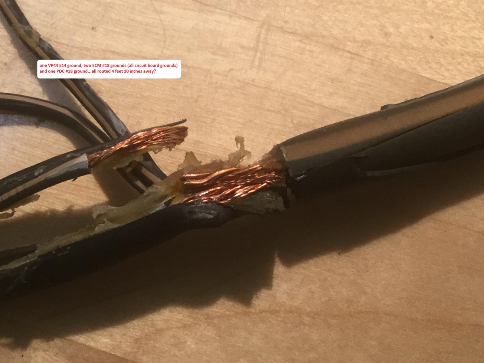
You will have only one robust line, from the drivers side battery positive terminal, connected to the PDC. The alternator + terminal directly feeds the passenger side battery + terminal. All of my high current lines are #4 gauge copper welding cable. Note the single #4 gauge connected to the output terminal of the alternator is a short run directly to the + terminal of the auxiliary (passenger side) battery. There is NO high current wire passing in front of the engine within the loom because you have removed that OE line in this modification. The only wires within the loom are: 1) two wires (blue and green) that control the alternator 2) the air conditioning compressor clutch control line 3) the water temperature signal line This simplifies the loom and you can eliminate the "fat plastic" loom with smaller diameter plastic tubing to enhance appearance. You presently have a single #1 gauge running across the top of your radiator between both batteries. This single robust line connects both batteries in parallel at the positive posts. The negative parallel connections between both batteries is provided by chassis and engine block grounding. If you wish to perform this entire modification correctly, you double strap both batteries into compliance. This is the correct method in order to fully "parallel" both storage cells. The "double strap" method is the engineering standard to provide absolute error free paralleling of large storage cells. The OE factory method was applied because it's cheap and dirty. Multiple connections at the battery becomes difficult, batteries that provide top and side-mount connections makes the job easy. You are creating a power supply and removing errors that arrived from the factory. This modification was to remove the high current charge line of the alternator and eliminate "ripple" noise generated by the alternator from sympathetically entering the small signal leads within the loom that causes other electronic errors. This modification eliminates the haphazard "crush-splice" procedure sealed in glue and shrink-tubing. This modification provides correct grounding methods for the ECM and PCM. The PCM relies on the battery temperature sensor under the drivers side battery to calculate charge rate. Double strapping both storage cells removes any error and places both cells at absolute equivalence to assure the PCM is receiving absolute temperature data in a "parallel" charge configuration. The batteries are to be treated as a "single" source of energy, this method is military-space junk hardened and represents technical excellence. W-T
.jpg.9066186842bcb3a5428bf2d0cd541518.jpg)
.jpg.ed9d95996db640ae93888fc76470078b.jpg)
.jpg.97c20a43a59240a3076f017d8c71733d.jpg)
-
@Timburrr Caution, please re-read the instructions. The +12 volts from the drivers side battery is supplied to the PDC. It's a short distance, less than 14 inches to reach the positive terminal on the drivers side. You can use a short piece of #6 gauge to supply the PDC directly from the drivers side and you will have no issues. W-T
-
Yeah...John @Tractorman brought a few aspects to my attention that need clarification to this issue for @Doubletrouble The run-time for the lift pump in a freeze-up situation is dependent on how hard frozen is it? Also, where is the frozen obstruction or resistance? My error in stating "Let the Raptor Run" is not fully correct and needs to be tempered in application. BTW...prior to applying a new lift pump installation on my vehicle, I would use this "TEST lead, force run" procedure when I would change the fuel filter in the Stock Filter canister. This simple maintenance procedure always evacuates the fuel within the canister as you remove the filter element. Once done, I'd reapply the cap and tighten to prevent leaks. Knowing, I had air in the system, I elected to "force run" my lift pump to purge the system prior to starting the engine. This procedure actually trained my "ear" as to what was occurring within the circulatory system by the way it sounded as it hydraulically chased the air from the system. It is a subtle but, very profound audio report and you need to experience this to gain the auditory perception of its action. It is also an advantage to have a working fuel pressure gauge to visually monitor "what you hear" as the hydraulic system stabilizes. Viewing the gauge as you "force run" the lift pump you'll see some wild excursions as the system purges the large volume of air and begins to become a "pure air free" liquid environment. It requires "run time" to actually hear the system clean up...as the lift pump continues to run, you will hear the finalization of complete purge and your system will have a certain sound that is very particular.... it sings it's own song. On initial activation of the lift pump in this "forced run TEST" the sound is raucous and glancing at your fuel pressure gauge instantaneously will be alarming as the needle will slam itself violently as the purge initially is vacated then, you will begin to hear stabilization but, additional run time is still required as the fuel pushes the last remaining air pockets from the system. The entire lift pump circulatory system will adopt it's own sound and remain at that same sound once fully burped. This "TEST force run" of the lift pump with the engine NOT running is an enlightening experience and one should know the "song" of your system. Each system has a different song and depends on what devices are selected in the assembly. I know that Dan @IBMobile made reference to force running a lift pump in a thread sometime back, so this TEST procedure is not new. Flow through is important, even if its just a dribble of fuel indicating liquid fuel is present within the vane cavity of the transfer pump. My blanket statement to @Doubletroubleto "Let the Raptor Run" in this "TEST force run" is in error! The examples @Tractorman posted regarding "waxing" in cold conditions is a major consideration where NO flow through is occurring. In a common sense aspect, if the system is gelled-up at a particular location within the system, inadvertently placing your lift pump into a "forced TEST run condition" for an extended period of time could damage the lift pump seals following the love-joy coupling at the impeller disk. I ask forgiveness in following verbal dissertation...if you know the "song" your system sings when all is correctly flowing, you will know when the song goes wrong. The lift pump in a harsh low temperature situation maybe looking into a "dead headed" no flow pathway, if there is just a small fraction of liquid fuel within the cavity of the pump, it will be in cavitation and extended run periods could cause damage. With this cautionary knowledge one would call on a reasonable consideration when placing the transfer pump into extended forced run operation. In my experience, I'd be listening for the song. Knowing of the cold storm situation in the eastern states this winter, there is most likely, additional cold-start event errors forthcoming. I'm originally from Butte, Montana and I've seen -60 F however; my 2nd Gen has only seen -20 F and I had no errors. Humble Respect, W-T
-
John, of course...I'm just doodling in the office. It's early Christmas morning and still sober...not for long
-
Sorry for your troubles. If the LP is in the stock location, I would hope you are providing the DC through an isolation relay? The original 12 volt trigger line that powered the OE LP is the line you use to trigger the isolation relay. The isolation relay only sinks about 20 or 30 milliamps directly from the MOSFET driver in the ECU. The original LP would sink about 5 amps off this circuit because the little Carter LP is a peanut whistle pump. The AirDog Raptor most likely sinks about 7 to perhaps 8 Amps....the isolation Relay eliminates the current demand from the MOSFET driver within the ECU because it is no longer powering the OE LP...this is a good thing. Not an issue, your Raptor has the ability to purge the filter canister and out-flow the residual air through the over-flow valve at the rear of the cylinder head when the CTD is NOT running. Good, you got it to "show fuel pressure" NOW stop this "twenty second" run stuff right NOW! Get yourself a couple of test leads with little alligator clips about 12 inches long or perhaps longer (no worries) Un-plug the trigger line from the ECU that "is supposed to be" triggering the isolation relay. Take your test leads and connect them to the relay coil pigtail that was previously connected to the ECU trigger line. Now, take your test leads and source 12 volts directly to activate the isolation relay. This will force your Raptor into "a continuous run" condition, because you have manually provided 12 volts to trigger the relay. You should hear the Raptor run immediately when you trigger the isolation relay. LET IT RUN ! NOW, go open your fuel filler door, remove the fuel cap and put your ear to the hole at the filler-neck and listen. Once you hear fuel being returned to the tank you should see fuel pressure. If NOT, your "peanut-whistle" feed-line has a frozen booger clogging the pathway. Good, leave the 6 Amp charger hooked up while you do this and let the Raptor RUN ! NOTE: quiet conditions are required when you are trying to hear liquid flow being returned to the tank. I know it's cold and miserable at your location...stay with me... In this "force run condition" this effort may require getting under the vehicle with an industrial heat gun and began "heat tracing" your peanut-whistle fuel lines. BOTH feed and return must be HEATED to restore the full circulatory aspect of your system. It will cause NO harm to continuously force run your Raptor in this TEST scenario and the battery charger will prevent pulling the head-charge off your storage cells. The force run condition without the CTD rumbling in your ears should allow you to "listen" for success once the system is fully purged and free-flowing. Most likely, you'll see a fuel pressure indication once flow is achieved. I strongly believe following these suggestions carefully and remaining focused on the details will yield successful results. Removing your temporary test leads and restoring your ECU trigger line to the isolation relay, returns your system to standard operational condition. Please, do NOT "test lead" 12 volts into the ECU trigger line...that, is a direct act of buffoonery! Merry Christmas W-T
-
-
Hey John, I did review your post on Monday this week however; I've been so busy I hadn't had the chance to digest and respond appropriately to your very well thought out contribution in this subject matter. The history of the 2nd Gen platforms have been mauled over for twenty years now and the "tribal knowledge" many of the participants have gleaned has come at the price of success and failures of others. The care and feeding of the VP44 became a focus point in much of the earlier years due to the method DaimlerChrysler elected to transfer fuel to the working VP44. TDR, Turbo Diesel Register had a large following at the time and their printed magazine had many comprehensive articles on various subjects revolving around the VP44. With outraged customers who purchased a 2nd Gen platform to experience Injection Pump failures at fairly early intervals, typically less than 100K miles, the frustrations with dealerships grew to alarming levels. I'm not referring to the "wire tap" roll-coal enthusiasts who blatantly voided their factory warranty with stealth-cap wire tap modifications or worse, being it is a totally visual modification, easily discoverable by novice dealership technicians. It reminds me of the Seinfeld episode with the "Soup Nazi" NO SOUP FOR YOU...or No Warranty for You. I wish I had the time to thumb through all my early TDR magazines to find the actual articles where the information came from the actual manufacturers of the related components and the arguments between Cummins, Daimler Chrysler and Carter (the OE transfer pump) manufacturers. This is why I made reference to "tribal knowledge" having gone back in time twenty plus years...I know these things but, I don't recall how I came to know the details. I'll attempt to parlay some basic recollections of small but, important data that Carter stipulated regarding their recommendation to "pump placement" or location. Carter told Cummins the transfer pump is to be located within 24 inches of the fuel supply reservoir. This is printed documentation that arrives with each pump in the box, brand new. Daimler Chrysler told Cummins NO, we want the entire Engine as a "drop in module" with fuel supply devices attached as an assembly. I don't wish to beat a dead horse here...but, I think this maybe a key point where all of this buffoonery began and still, to this day, misconceptions prevail. I truly appreciate the prowess of the obviously advanced Diesel mechanics or technicians who have contributed their findings or discoveries in various forums. Also, it is interesting to note the "technical excellence" across the web forums varies according to Joundra of a given site. I believe this site has merit and the historical talent that has made valuable contributions over time, can not be discounted. My background has a few eclectic sojourns in various industrial environments. It has allowed me to dabble as an inquisitive nerd over a vast selection of endeavors for personal satisfaction and household support. The last 30 plus years, as a "slang term" I was referred to as a "pump-man" and worked in the field of Fluid Management. I've worked with and repaired nearly every pump configuration imaginable on this planet. Double action displacement, single action, gear rotor, vane and diaphragm, Plural component hot and cold, just, to mention a few. The liquid products being pumped or manipulated, varied from light weight volatiles, heavy mastics, intumescent coatings, residential and industrial coatings, sporting event field striping, Interstate, Highway and city street line striping ect...ect... yeah, I know....boring stuff but, the Space Shuttle heat-shield Tile adhesive plural component project was out of this world. Sorry, not trying to over power the subject...just highlighting a foundational background. I had the pleasure of providing operational maintenance and repair seminars to large and small organizations with mechanically inclined shop employees. The primary aspect of focus was to stress the importance of never allowing the pump to run dry. Never, "Dry Stroke Your Pump" for the shear fact that the liquid nature of the vehicle, regardless of it's chemical composition is the "lubricating" shield between working mated surfaces. Repair or refurbishment of a given pump that has been inadvertently "dry stroked" for even fractional amounts of time cause immediate damage and hinders the operational longevity of the internal components. This is much more prevalent in a "high pressure" scenario with "thin bodied" liquid materials and leads to additional operational cost factors. In our case, an on the road failure is always a stress filled event that could or should be avoided through disciplines as a diesel engine owner/operator. The aspect of lubricity in diesel fuel and how it is formulated is a worth while subject all it's own. I hadn't paid much attention and gleaned some very important knowledge from @Mopar1973Manin our early correspondence . It also included the important aspect of liquid flow volume to enhance cooling of the high pressure VP44's internal components to enhance longevity over thousands of repeated heat soak cycles. I took the time yesterday to call @dieselautopowerand spoke with Lenny about the changes that have occurred with Bosch and the VP44 re-manufacturing details. His background knowledge is outstanding and he brought several aspects to my attention that needed clarification. It appears Bosch, did indeed, make some critical changes in materials used in construction. Most notably, the sleeve, previously made from aluminum (sheeesh) is now an alloy steel sleeve...yeah no brainier here...along with many enhanced internal working components. He also informed me the PSG circuit board control device has been enhanced for longevity. The changes that Lenny referred to, have most definitely made an impact on how long these pumps will remain fully operational. He assured me the failures they are seeing now, are almost exclusively electronic related failures and internal part wear or failure has become quite rare in comparison. This alone, may very well, take the aspect of doping fuel with one ounce (per gallon) of TCW-3 two-stroke to a lesser degree of urgency. I don't believe anyone would debate the aspect of our 2nd Gen CTD's being produced during the "low sulfur" formulation and the cautionary note we all took when Ultra Low Sulfur fuel was introduced. With Mike M1973M enlightening the forum with Scarification principles and standards, the fix of providing lost lubricity became a standard practice for myself and many others. It just seemed to be good common sense. The volume or flow through quench, of the fuel, to enhance or 'strip off" heat, through liquid exchange is nothing new, I believe most new fuel injected vehicles are all dumping more fuel back into the tank as a full circulatory system than ever before. If it's for cooling purposes, I don't know for sure, perhaps it's just volume for that occasional WOT and avoids fuel starvation in all conditions. I touched this subject with Lenny at DAP in regard to the principle of heat dispersion through flow-volume and he guided my thoughts around "heat cycles" before failure. Bosch has made changes to the electronics of the PSG circuit board with "heat cycle" periods being the main focus and to gain longevity. I was curious as to what Bosch might have done at component level but, Lenny assured me, Bosch keeps such information as proprietary and won't divulge the intricate details. However, heat is the negative aspect for run failure in nearly every electromechanical device over a period of time. Close inspection of how Bosch cast the housing with regard to how the PSG circuit board is embedded in it's mounting location to shed heat from the surrounding structure is not how I would have engineered it. Being that fuel flowing during run time is one aspect, the heat-soak after shut down is the issue Bosch was most certainly addressing. The board is all surface mount components and the composition of the small capacitors on the board are most likely standard ceramic with standard heat coefficients...they'd last a life time in a tabletop clock radio in your bedroom but, in this environment of heat-soak I'd have elected to place Tantalum caps as a superior component in high heat environments. Cost wise... ceramics are 5 cents, Tantalum are 18 cents. The shut down of a CTD in July in Phoenix Arizona after a hard pull or run on the Interstate is the worst case scenario for that little circuit board to just sit there and cook...as I pointed out to Lenny at DAP there is a way of providing cool-down to the PSG after shut down with a Pelter Junction device. I purposed my fix as a timed circuit to provide DC for 20 minuets and then terminate the cycle. The Pelter Junction is a fascinating device that operates at a fairly low current consumption and once you provide 12 volts DC to the device (shaped like a flat faced playing card) that is in direct contact with the circuit board, one side of the Pelter Junction becomes very cold and the other side is hot...this becomes a solid state heat sink or heat inducer, depending on what side you are working with. The aspect of getting it nested within the cavity of the mounting location within the VP44 will be a small challenge. It could be activated on start up of the CTD and have a simple timer like a 555 controlling the "after shut down" timing interval to scavenge the "heat soak" in a reasonable time interval. The little control could have a knob to adjust the length of time the device operates. I do regret using the term Imperative, I do realize there is a balance when conveying a message or thought...my habit of getting a bunch of rowdy blue collar butt-cracks to pay attention during a seminar so the owner or Boss is happier with their new $60,000.00 device.... because the "guys" know how to trouble shoot and fix it. This subject of lubricity and additional fuel flow has certainly been tossed around for twenty plus years. The enthusiasts who partake and share findings is a main reason for my interest and participation. John, your findings and documentation are always of great interest to me, besides, your a pump man! So @Basranabread...my apologies for semi hijacking your thread with peripheral data. Only @IBMobile remained focused to directly assist this member. On closing my rant...if anyone can procure a Bosch flow-bench, and allow me to use it, (oh heck, just give it to me) I'll build VP44's that you'll only purchase once. You know...the CTD is a pump, feeding a pump that feeds a pump...gosh it's a pump mans NIRVANA ! Merry Christmas W-T
-
That was a good decision, BD has been providing those for years and I'd like to chat with the individual who suggested that to begin with. It is a poorly thought out application. It need not be a Fluke however; there are several manufacturers who produce very acceptable DVM's The difficulty in looking at a complex or dirty wave form with a DVM comes down to sophistication in design. Preferably, a shop oscilloscope will allow flawless AC coupling on a DC line and provide peak-to-peak amplitude measurements with precision in regard to residual ripple peak values. This level of "noise" or "ripple" should normally be very low due to the immense storage capacity of the two parallel batteries connected directly to the output stud on the alternator. The capacitance of the two batteries is huge and normally provides excellent filtering (or smoothing) of the rectified DC present at the output of the alternator. Using an acceptable DVM will allow you to see the presence of AC ripple on the DC rail but, the actual peak amplitude for measurement is usually questionable. Having a DVM is better than NOT having one for basic work. May I suggest what Mike M1973M had uncovered many years back.... disconnect the B+ line from the alternator stud and go for a test drive. If you find the "lock-unlock" syndrome goes away, this identifies excessive AC ripple emanating from the alternator that can not be corrected with the lumped capacitance of the storage batteries. In this scenario one of the diodes within the alternator is "open" and this produces very ugly unruly AC ripple. Yes, it's still DC but, it has hair all over it! Please note, the actual alternator's frame is at ground and the integrity of that ground is dependent on how clean the mounting bolts and structure are in respect to current flow being generated. I did sense your aptitude in a technical aspect of electronics...try your .1 Mfd on the EdgeComp DC line-in, keep the leads very short...you can't hurt or damage your Edge device by applying a capacitive shunt to ground...it acts as a broadband RF filter. This might alleviate the spooky issue when you travel through the "RF hot spot" I know you can't drive for miles without having the alternator replenishing the storage batteries but, day time drive, no headlights, no music and NO grid heaters...take the time to see if divorcing the alternator from the system eliminates the "lock-unlock" syndrome. Sorry...task master issuing orders...let me know what you observe. W-T
-
When I was 12 years old I noticed the old guys (16 & 17 year old dudes) had jobs, a cool car and a pretty girl hanging around when they were washing their cars...I took note right away of the proper order of things... Job...cool wheels and wow, girls! It is especially fun if they are short and require help to get into a lifted CTD when wearing a short skirt my bad W-T

-
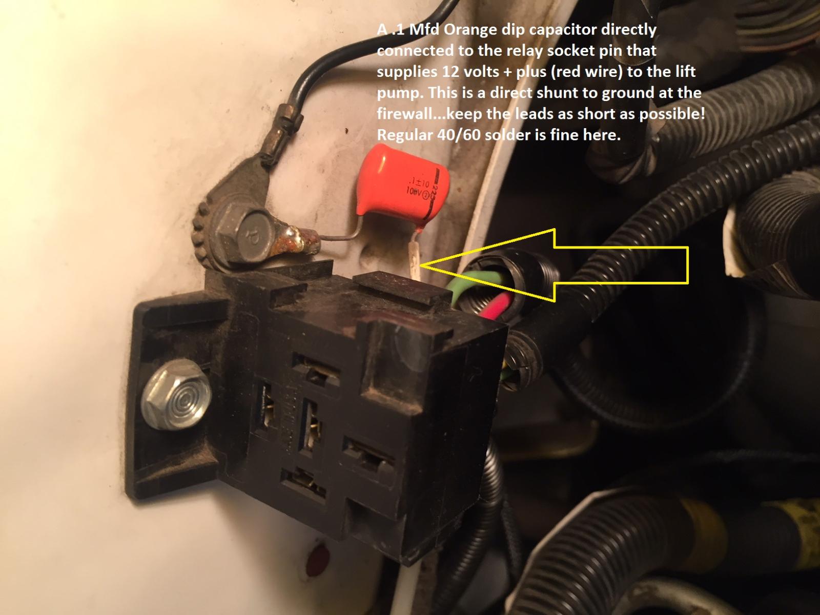
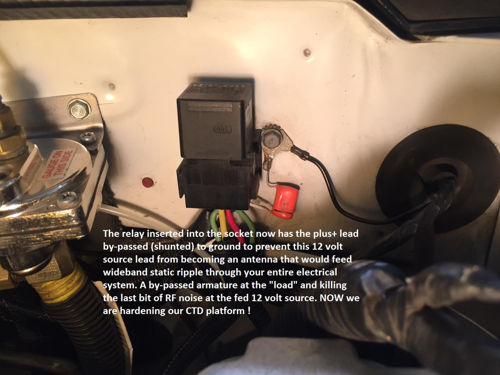
Yeah...I do have a tendency to get carried away in a verbal dissertation however; I prefer more information than skimpy hit-and-miss on subject matter. Now that you've had time to make additional careful observations and seeing the subtle telemetry faux pas certainly appears to be a condition of outside source(s) permeating your electronics. The test and headache of divorcing the Edge instrument would narrow the search for "what" is being effected. This is just a simple example of "shunting" or by-passing the +12 DC supply line that is fed via the relay to the lift pump. It's a .1 Mfd Orange dip capacitor with short leads connected to ground. This was the last step to remove the residual "DC noise" emanating from the armature of the aftermarket lift pump. The pump is frame mounted near the rear of the vehicle and the +12 volt DC line is approximately 9 feet long. I found the B+ line to have a trace amount of harmful wideband RF noise and by "shunting" that line at the relay socket directly to ground eliminated all of the hash 100%. The cost of such capacitors is just pennies and you may very well have some in a junk box somewhere? I selected the .1 Mfd because I knew I was looking for lower frequency noise...in your case, I would choose .01 Mfd as a starting point. In an experiment I would shunt your +12 volt feed to ground directly at the EdgeComp box. This would alleviate any stray RF entering the device on the 12 volt rail. This is all just experimental if, you find the error to be eliminated when you divorce the EdgeComp and verify the instability with the EdgeComp being operational. This procedure is just step 1 and by-passing the DC at a suspected device is always step 1 because dirty DC is distributed through the entire circuit board of the suspect device. How EdgeComp produces their device is unknown to me...if anyone has a full service schematic of their device(s) I'd like to see it. Most of these types of devices are not fully documented for the protection of the design. They don't like people looking at their products in this fashion. I like to view full engineered schematics to review the basics and not the secret design parameters. It's the small basics these companies overlook in design layout that cause these electronic gremlins to be such a bother. My information to you revolves around "Rf interference" and my examples are only "on board" interference devices however; this plays hand in hand with outside source extraneous RF fields too. I realize you have several cables/lines exiting the EdgeComp box to various points of connection and for a starting point I always suggest to start at the basic point of +12 volt supply line....because it feeds everything. Let me know as you proceed...there are many hints and kinks to share in this subject. Cheers, W-T
-
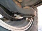
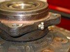
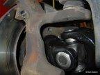
The size of these photos are poor... I don't recall where I copied these from but, it was back in 2009 I believe this was from TDR and one of the members had drilled and tapped the housings to insert a Zerk fitting I've always wanted to perform this modification...once the fire hit, my shop was eliminated just as I was in the ready to perform the task I strongly feel this particular effort is worth while. W-T

-
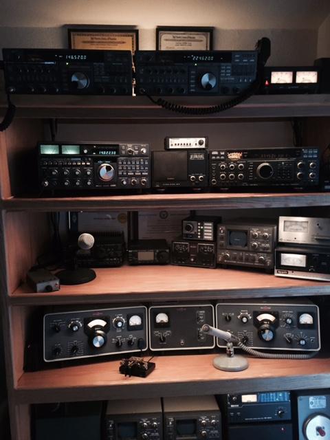
Hey Neal, the aspects of RF follow strict engineering guidelines and a little black magic in practice. The commercial Broadcast frequency allotment for AM (amplitude modulation) falls in the spectrum between 540 KHz and 1.6 Mhz and that carries over into your geographical corner of the world. There are only 3 ITU (International Telecommunications Union) regions world wide. You are in ITU region 1 along with all of Europe including the middle East, the US, Canada and South America are designated in ITU region 2 and all of Asia to the Philippines including Australia, New Zealand, Pacific Islands and Hawaii are designated ITU region 3. The ITU is worldwide with over 280 countries (North Korea not included) and they all agree to the frequency spectrum divisional standards. This assists manufacturers producing radios, televisions, cell phones...ect. to be on the same page from a frequency or channelized standpoint for worldwide distribution, The AM broadcast band is subject to band conditions on a daily basis along with solar conditions that vary over an 11 year period of time. The low frequencies being used for AM Broadcast are located on the bottom edge of the (old terminology) Short Wave band...and serves its purpose quite well. In regard to our "receivers" in these CTD platforms none of them are considered reference receivers. None of the worldwide Automobile manufacturers incorporate bullet-prof radio receivers into their products. The tremendous noise or interference you're encountering in that specific area, that has an audio envelope exceeding that of the desired (legitimate) station's signal appears to be fundamental overload of your receiver. Simply, the RF radiation in that particular location is most likely a spur or birdie from the generating device or it's a direct fundamental RF field emanating illegally from the generating source. If it is NOT a legitimate licensed Broadcast facility and this interference exceeds a distance of 300 meters from the generating source with a force greater than X micro-volts per meter (RF amplitude measurement) then you have found a law-breaker. The commercial Broadcast stations in that geographical area would be very displeased to have their signal being jammed by an extraneous RF signal source. All electronic devices shall not generate harmful interference to commercial, law enforcement, aviation, military or home electronic entertainment devices. All it takes is one person who wishes to receive a legitimate broadcast signal, make a complaint and show the actual interfering signal compromising the quality of the desired signal. If there is a device operating on the premises of this industrial location that is producing this "hash" on the commercial Broadcast band and you bring this to their attention...their engineering staff or management should take this seriously. Ignorance of the law in regard to RF radiation exceeding predetermined levels of acceptance can be met with fines exceeding $10,000.00 each day of non-compliance. Regarding your receiver, they are standard dual conversion Superhetrodyne in design. Its a reliable and stable form of demodulating a RF envelope and extracting the audio information from the fundamental carrier frequency. Many are quite good, some are just marginal with reasonable sensitivity however; none of them can perform properly in a strong RF field of radiation. Reference receivers used in specialized facilities or military installations adopt Rohde & Schwarz ($40,000.00) Rockwell Collins ($30,000.00) and others in the tens of thousands of $ make excellent receiver/demodulators and well beyond our automotive needs. Non the less, you've found a source of undesirable RF with your radio receiver and it came with the truck...no additional investment required. Your suspicion of large inductive electromechanical single or three phase motors are suspect but, they should operate with broadband interference levels not exceeding 10 to 30 meters in distance. Neal, you probably wished you hadn't asked...and I haven't even began to go off the rails yet but, it's Sunday evening and I should go find a cold pint...let me know if you decide to go look around that facility? Take a little transistor pocket radio with you...I'd bet you can walk right up to the generating source. Oh...here is a photo of some radios....I assault the planet with these. Cheers, W-T
-
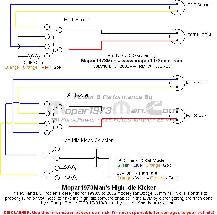
When Nic @Me78569 built the last run of these boards with switch and connection leads, it was a complete package. Basically plug and play with the most time spent determining where you would place the control for operation. The length of the leads allowed versatile placement within the cab of the truck for convenient operation. The construction was very nice and the last run had incorporated SMC (surface mount components) that shrank the size of the board and allowed the small 4 position switch to be directly mounted to the board. The small size was conducive to place the control board into nearly any location for drivers convenience. Over all @Rivclark44 this project is quite easy to reproduce as Mike @Mopar1973Man has done the homework on this to place fixed resistance values in line to fool the ECM into 'High Idle or 3 cyl Idle' when selected by the operator. These boards work very well and the design is not a high current contraption so reliability is outstanding. The guys here have suggested obtaining a Smarty 03 to enable the Factory Program to be activated or go to your trusted Dealer and have them activate the software if it has NOT been activated previously. I'm sorry, to not be able to assist you in creating a working 'High Idle' board as my shop and electronic lab was destroyed in the Paradise CA fire back in November of 2018. The loss is still effecting me four years later. The working shop was quite advanced in several eclectic electronic ventures. If you elected to pursue this project, you needn't make it as sweet as Nic did (from a size aspect) but, you would have the operational features you're looking for. I'm sure Nic and Mike would provide guidance on part procurement aspects. The etched circuit board is not required and you could cobble the fixed resistance values in 1/8 watt packages directly to the rotary switch...there is NO current present on these 5 volt sensor rails so this entire assembly is very easy to assemble. W-T
-
It really shouldn't matter as long as you have serviceability access once it's mounted in the selected location. The location should provide protection from road debris to prevent damage. Recently, I had observed a fellow in Redding CA where he had mounted his after market transfer pump assembly fully exposed. I laughed thinking this character must want everyone to see his work...in fact, it was on display with both filters hanging down in full view. I wonder how long it will be before it's damaged or someone steals it...after all...it is "on display". Cheers, W-T