

W-T
Yearly Subscription
-
Joined
-
Last visited
Everything posted by W-T
-
Being this is November 8th, I'm looking forward to seeing a change on the horizon for the better...and I'm not eluding to Standard Daylight time.
-
It is a curious anomaly in today's automotive world where interference from some unrelated instrument causes issues with an onboard electronic component. I did see your coordinates along with the distance traveled to be very minimal and I'm only guessing...the exact location may be a pathway of unknown RF radiation. I experienced an oddity near Boeing Field in South Seattle where my alarm system would falsely arm itself and trigger the alarm when I activated the lock from my key-fob. With all the large and small micro-wave dishes only 100 yards away pointing directly at the parking lot where my vehicle sat, I experimented and moved my vehicle 60 yards. The next morning, I noted no alarm error as I manipulated the key-fob. The hotel is the one I always stayed at on company business every other month so, I had time to make these observations over a period of time. I realize looking for an electronic Gremlin like this is extremely troublesome. If indeed, you are traveling through a "RF hot spot" momentarily, it is most likely not the fault of the RF generators. To verify this potential field of RF requires some sophisticated electronic test instruments such as a Panoramic Spectrum Analyzer. The monetary value exceeds 25 thousand dollars and most DIY automotive guys don't do this. If you had a friend working in Cellular or commercial Trunk-radio systems. they would have access to such devices. Driving to the area where you have experienced this error and having this device would reveal if an RF field of radiation is permeating the area of question. Time involved in this would not exceed ten minuets. (finding a guy to go chase rabbits like this is the tuff part) If...this is so, then the job begins to locate the sympathetic multi-lead connections that are transporting the offending RF signal into the automotive system. Usually, it's just DC lines that were not properly "by-passed" or "filtered" at the point of entry to the PC board. Our CTD's like all the manufacturers, do not "Research and Develop" military combat grade electronic readiness into civilian vehicles. Don't be concerned, the fix is typically a .1 uF dip capacitor from a DC power lead tied to ground with very short leads. Cost wise...about 35 cents but, you need to know what lead and where. Yeah...I know...we be having fun now and yes, it will take a little time but, it is not impossible. I would be interested to know what your findings are after you divorce the EdgeComp from the system and make a few passes up and down that road. W-T
-
@2000Ram2500 I've carefully read the information in this post and it is interesting. This short stretch of road, where you experience this phenomena, how much time is elapsing from the point where you notice the error and where it curtails? Is it always at the same "speed" or, does the error occur at any given speed you happen to be at? Is this the ONLY place you've experienced this error? I see that it occurs on either side of the road so I'm assuming you travel this road going to and from your residence on a fairly consistent basis? In this aspect, I must concur with @IBMobile and encourage you to disengage the EdgeComp to see if this error terminates in the same driving scenario you've indicated. Sorry to become a task-master however; your observations are key points in developing a theoretical analysis. Respectfully, W-T
-
@Reaper22your report of 13.7 volts DC charge is a good sign you've corrected what had plagued your system. This thread has two focus aspects and I'm late in arriving to the fray of it all and I'll attempt to be concise with my contribution. The "term" noise on the rectified DC output of a given alternator is becoming an issue. An Alternator does produce rectified DC with a certain amount of ripple that is very normal when diodes are used to rectify an AC wave form. In practice of creating a DC power supply, the rectifiers are always followed by a form of filtering, being capacitors or a swinging choke that "smooths the ripple" to a much lower level. The standard alternators being used in these CTD's are "3 phase" and when you view the DC output on a shop oscilloscope you'll see the little "camel humps" riding on the DC reference level. The amplitude of these "camel humps" is minimal when referenced to the overall DC potential being generated. You should view this as ripple not noise. The parallel batteries present a tremendous amount of capacitance to "filter" and nearly remove all of the "little camel humps" left over from the rectification process resulting in a substantially clean 12 volt DC rail. Attention to clean terminals, correctly terminated connections and healthy heavy gauge wire firmly tightened into operational condition is best practice. I do believe your efforts have provided improvements due to the age of your CTD platform and alleviated the factory errors by delving into the WT ground MOD. I do encourage you to follow the original article and "double strap" your batteries into a fully compliant parallel configuration to provide absolute strapped capacitance and provide error free charge rate for the Battery Temperature Sensor kissing the bottom case of your driver's side battery. The B+ initial current, from the alternator, now enters the passenger side first and the PCM is monitoring the "thermometer" in the baby's butt at the drivers side battery. Double strapping is the only way to avoid lopsided capacitance for proper filtering and temperature charge rate monitoring with NO error! This procedure has NOTHING to do with voltage drop. NOW...as for NOISE The alternator has a set of brushes that come into contact with the "collector rings", commonly referred to as "slip rings" and this is your "random" noise source within a given alternator. They wear and go through physical changes in time of use. The accidental BUFFOONERY of touching plus to minus battery terminals while the engine is at idle with a conductive tool for just a micro-second causes damage to the collector rings and brushes. Improperly applying jumper cables to assist a fellow motorist with a "real dead" battery is also a wear point to consider because the immense current flow at the initial point of "contact" blows away the metal structure of the collector rings and brushes at precise locations over the 360 degree rotation surface. This abnormality of a current conductive surface "making and breaking" for only fractional moments of time becomes an "Arc transmitter" and produces copious amounts of random electromagnetic and electrostatic noise. Viewing this on a shop oscilloscope will appear as "hairy fuzz" encompassing your DC rail. This is "real" noise and NOT ripple from the rectification circuit. Having a hand held Digital Volt Meter (DVM) will not show you noise, it only displays ripple (when AC coupled) on the DC rail however; noise on a DC rail renders a DVM to display erroneous levels in amplitude. A shop or laboratory oscilloscope is the only method to assure absolute accuracy. Build your DC power supply (alternator & batteries) with excellent interconnecting cables and terminations for clean unadulterated DC integrity to supply the system clean voltage...all of the interrelated electronic wizardry will perform correctly. Standard run-of-the-mill procedures are not a measure of excellence...it is budgetary. Cheers, W-T
-
@wil440a properly maintained aquarium is certainly a nice addition to a living environment. In the past I had several tanks and it created a peaceful atmosphere with an artistic flare. Fresh water was my limit, I found salt to be too demanding and expensive. I found sub aquatic plants extremely interesting and pursued many complimentary species...funny note, the fish were there only to provide natural nutrients and promote a balanced environment. The submerged garden was certainly a beautiful presentation in my modest living room. Your post, brought back some pleasant recollection of times past. Cheers, W-T
-
Welcome to the forum, as you review many articles I'm sure you'll find additional information to be quite informative. Don't be hesitant to ask additional questions, you'll find the participants on this site to be highly considerate. Older subject matter is welcomed for reiteration and reevaluation...your participation is appreciated. Cheers, W-T
-
Good on you Loren that you can work through the commie flu...your art work looks good. Lets go Brandon! Cheers, W-T
-
@Sycostang67I just wanted to say, NICE truck...love the color, it looks bad to the bone!
-
Hey Loren, https://www.hifisoundconnection.com/Shop/Control/fp/tcat/92727/SFV/30046 I use this type of pass-through seal assembly. The hole you create by size can be fitted with this style of water resistant seal. The cap when tightened will force the spongy-foam doughnut (sealing material) to comply with the diameter of your wire and provide an excellent seal. The body of this device arrives with a pliable rubber gasket that seals against the flat surface of your selected mount location. I noted this company is out of stock on all the sizes and only offer a 1 inch size however; these type of pass-through seal devices are available from many sources. I have successfully used these without any moisture or water incursion for years, and if you need to remove the wire or check something, just loosen the cap and slide your lead in or out of position. On my last purchase they were inexpensive, about $1.89 for 1/2 inch.
-
GW, I've asked enough of you and I do not wish to drag you through the mud. This is a remarkable project you've undertaken and I can only assume you're developing this for self satisfaction? I appreciate the effort in hope that we CTD enthusiasts may benefit with an added development and avoid obsolescence or discontinued critical control devices. There is no telling how long our platforms can be supported when companies discontinue supplying or servicing critical modules, @Auto Computer Specialistis certainly an answer to prolong the desire to operate these vehicles and I'm grateful that such facilities exist. Yeah, old school P7100 systems do work but, the advanced drive-ability of the modern electronic controlled VP-44 is superior in many aspects. I look forward to seeing further development, seeing a 'working beta platform' actually working(!) is exciting, you needn't have a nerd nit-picking circuit aspects that can be addressed when necessary. I truly appreciate what you're doing! W-T
-
GW, is it possible to view a schematic of this? I'm guessing this portion of the component count is being applied directly at the solenoid terminals or very close to it. I'm trying to picture the configuration and I'm guessing this is occurring at the top of the VP-44 as a modification directly to the PSG unit. Using a Zener and selecting it's value to accommodate the desired voltage at the knee of avalanche is a common practice however; applying Zener dynamics to eliminate the reverse EMF of a collapsing field is unorthodox. I would appreciate learning how that looks in schematic form and how this actually works?
-
Again @Great work!you're accomplished in this endeavor. Observing the limited scope reference of active duration for the "event" of opening and closing the plunger does depict the extremes of overshoot. The characteristics of any lumped inductance (solenoid coil) with substantial "windings count" would account for many micro-henries storing the DC charge in the surrounding electromagnetic field of force and collapsing into itself once the DC source is removed. A back-EMF, is what I recall from studies, ( I'm not trying to school you here) your clamping at 51 volts is my question? Not seeing an actual schematic have you incorporated an additional snubber circuit to soften or curtail this 51 volt spike? Again, please forgive my curiosity, I have the most outright respect for what you're creating here. As for what BOSCH has in it's original design layout, I've not even looked at it. You've opened my eyes to a heck of a lot and I'm barely worth the dirt under your finger nails at this point however; my sophomoric observations are just that. In the past, I've been quite assertive in simple aspects of basic DC and limited AC theory to assist fellow members to avoid or eliminate electrical noise that was introduced via factory design. These little faux pas cause errors elsewhere in these trucks. Onward...the original question pertaining to the switching supply regarding noise generation was my first thought, now you've also brought my attention to the internal solenoids of the VP-44...that 51 volt spike collapsing causes me concern from my humble view point. Not so much for noise but, for the aspect of longevity for proximity associated circuitry. I confess to having never done a direct panoramic spectrum analysis of the VP-44 in it's operation just to see what it's generating from DC to daylight. I'll share my observations with you once done, perhaps it maybe of value. P.S. I'd like to volunteer as a test subject in beta for what you might be producing. Thank you, W-T
-
Thank you @Tractorman indeed my suggestion was NOT with engine operating... In several additional reviews of @Andyba20 video it is pretty easy to see the velocity of the rear universal joint compared to the turning speed of the tire/rim. In correlation of the sound it appears to me that an out-of-round break drum is coming into contact with a break shoe for a specific portion of the rotation. I referred to this sound as a "moan" having an elongated duration to my sense of audio discrimination. Squeaking, pertaining to the spin-speed of the universal joint would have a much more constant audio- report, over a 360 degree rotation. Again, not being with Andy when he's trouble shooting, only allows a guess however; I'm leaning towards the possible drum break assembly. I say it's a "moan" not a "squeak". W-T
-
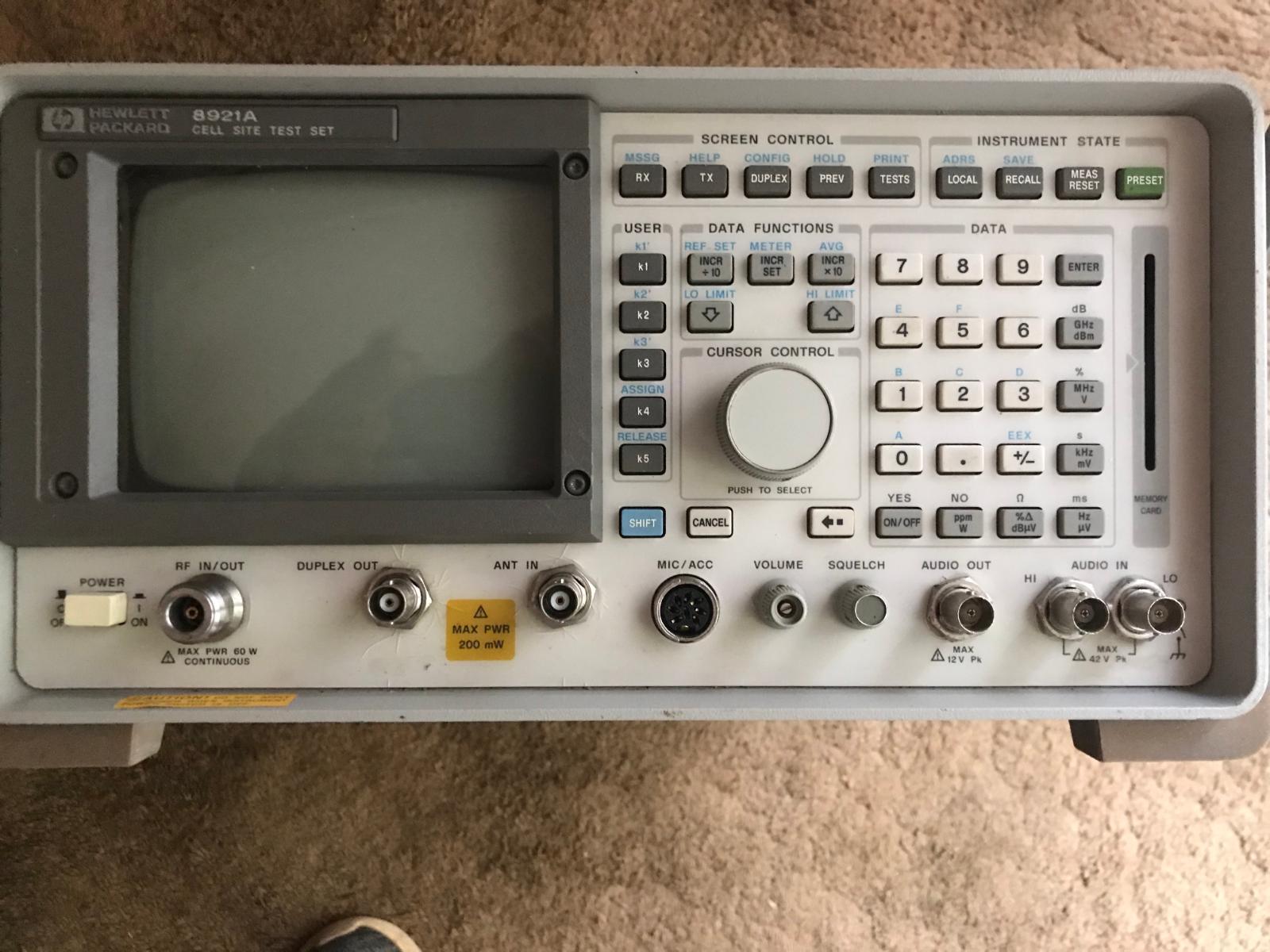
@Great work!yeah, I was thinking the CPU would be clocking faster than 8MHz to lengthen the sample rate bits. Linear regulation is wasteful and kudos on transferring to switching but, that spawns another curiosity, is it quiet? I work with a Hewlett Packard 8921A and I've eliminated several switching supplies from my equipment nest due to noise in the spectrum. This test instrument is good to 1 Gig and sensitivity is extreme. You mentioned the cost of the multi-pin connectors and I had not done any looking around Mouser or DigiKey , so I do not know who manufactured them (Molex?) and the reason was, I wanted to transfer the location of the ECU. I find the decision to bolt that damn thing to the engine block absolutely INSANE! Truly, it's a poor location for so many reasons... so, I thought I'd hunt down the connectors and create a high quality "relocation" harness. Your endeavor is beyond my thoughts however, I'd prefer to have a controller of this nature in a much friendlier environment. Just my two cents... I hadn't even contemplated the PSG so, again I'm following your work closely because of the nobility in nature. Yeah, I had to show off my HP....you know these sold new for 25K ....it's one of the reasons the last wife left. W-T
-
Yeah Andy, at the slow speed while backing up (I'm guessing here) since your rig is a 2000 do you have drum brakes in the rear? I'd jack up the rear, both tires off the ground, put the transfer case in neutral and hand turn the tires to see if you have a brake pad just slightly dragging. It's just a guess...that moaning reminds me of brakes. Again, only guessing here, my 2001 has four wheel disc brakes and I'm aware of the "glide-pins" becoming contaminated and causing drag also. W-T
-
GW I've always wondered what the clock speed is on the factory ECM and seeing your board, I do see the crystal at the 1:09 time, it is marked 8.000; is this 8Mhz as a reference and is this fundamental or are you deriving or extracting a multiple clocking speed? At 14.3 volts @ 7 amps I see your heat sink and fan...I'm assuming the driver(s) are being heat dissipated here....I must ask at 107 watts how warm is that heat sink after an extended period of run time. This is impressive and I have many questions. This is very exciting! W-T
-
Good on the M1 motorway run, no wobble is good! If you run them long enough with improved balance I'm guessing the lumpy uneven aspects may wear down and at least give you some time before paying for new rubber. The D load rating on the Toyo's is pretty good...I had Goodyears for a short time, the sidewalls were so weak, I was glad to move over to Toyos. I do think relying on the Dyna Beads exclusively for balance will be your best bet...let me know what you find.
-
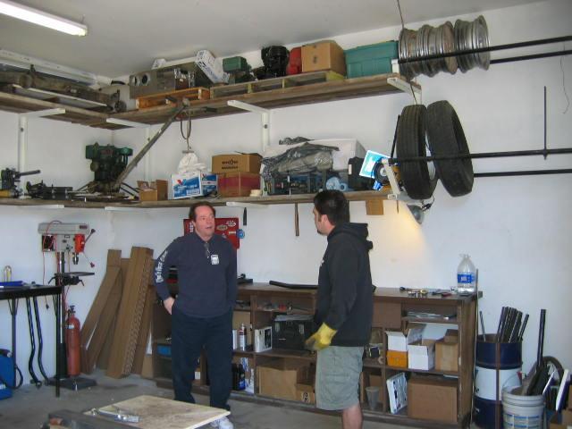
Wil...an irregular wear pattern on these aggressive lugged tyres will be an issue for a period of time. As to what caused this...I don't know but, rotation at every 3000 miles may alleviate some of the high spots eventually. I can only strongly suggest rotating in a specific pattern: The two fronts swap to the rear to the opposing sides. Your left front goes to the right rear and your right front goes to the left rear. Your rear tyres do not switch sides. Your left rear, goes forward on the left and your right rear goes forward on the right. This pattern procedure is normal and recommended for our trucks. I'm going to assume your tyre rotation may not have been accomplished at the 3K mile intervals? Static-balance would also need to be performed at each tyre rotation interval. Static balance is poor once the tyre sheds rubber as mileage is accumulated. That aspect is one of the primary reasons I elected to use the dynamic balance method provided by Dyna Beads. I must also strongly suggest adhering to the recommendation of REMOVING all static weights from your rims and allow the recommended amount of ONLY Dyna Beads to provide the distributed balance. From the looks of your provided photos, I would well imagine the road manners of this truck at highway speeds (or certain spot speeds) to be very unruly. At this point, you have "lumpy round things" that may improve over time and integrating new disciplines may allow you achieve better road manners along with extending the life of your investment, basic tyre cost. I do realize my previous statements my have caused alarm in comparing my CTD's road manners at speeds exceeding 100 MPH and considering the speed rating of my 37" Toyo's is a "Q" rating... meaning the manufacturer's DOT specifications, stipulate that 99 MPH is maximum safe speed .... I believe I may have achieved the limit with graceful accuracy. I must add, an additional observance of attention to tracking alignment of the front axle in symmetry to the rear axle. This is a photo of Don Thuren and myself at his previous shop in Santa Barbara CA discussing the importance of axle alignment between front and rear. Many 4x4 trucks do not track in a straight line, our trucks having the track-bar is what determines this geometry. Don asked me if I had ever noticed, when being in snow conditions, if I had ever noticed how the truck felt when going forward in a straight line? Specifically, "does my truck dog-leg"? He educated me by referring to the geometry of the suspension when moving in a perfect straight line of travel that the "rear" may dog-leg slightly to the right or left? I was truly thankful having had the opportunity to obtain a Don Thuren Track-Bar and have the Master actually install it at his home shop. He told me he doesn't do such things for other people but, once he viewed the cleanliness of this platform he went to work. The Track-Bar from Thuren is extremely robust and has a Heim-joint on the far right end to allow precision adjustment of the axle to match the geometry of the rear. He told me I was out of specification by more than a 1/4" and that the new alignment to track "perfectly straight" will make a substantial difference in the feel of "going straight", tire wear, and slight improvement in MPG. He reported seeing the majority of live-axle 4x4's not even being close, to avoiding the sideways "dog-leg" actions due to poor front to rear axle symmetry. The entire experience was worth the time, the results of having this track-bar applied and precisionally aligned to allow both axles to "track straight" gracefully enhanced the manners of this platform. Again, consistent symmetrical tyre wear and I do mean extreme uniformity in appearance along with road manners at all speeds (including ludicrous) is remarkable. I've taken rides with several acquaintances in their trucks. Then, I've taken them for a ride in Betty... they all remark in astounded exuberance of, "Geeeze I gotta fix my truck" I know I needn't speak of proper air pressure and the variation of temperatures effect on PSI and I don't think you're changing altitude between sea level and 7000 feet above sea level very often...so I must surmise the abnormalities your observing have occurred over an extended period of time. Tyres, 315's they are expensive, get rid of the static weights and tell me what you experience. At this point, it's gonna be a bit lumpy. Cheers, W-T
-
I've been watching the show on Paramount Network, Yellowstone (it's a kick a** show) and I must say all the fine Dodge Cummins 2500 and 3500 trucks are beautiful but, I was cringing several times when the hot moments in certain episodes where the CTD's were shut down quickly as the cowboys bailed out for action. Yeah, it's only TV but, I really enjoy the show. BTW...wish I could find a Beth Dutton some where...she'd most likely kill me but, wow, what a ride!
-
Hey @wil440excellent procedure and I too have been using Dyna Beads for 17 years with outstanding results. The company who produce the mini ceramic beads is on the east coast of the US and the composition of the ceramic material is formulated to be neutral in regard to static charge build up in order to negate clumping of the material. Dyna Bead's web site is comprehensive in specific application as to what size tire and rim combination your working with. My background in electronic communication evolved into Space Communications and I became affiliated with some very interesting individuals in NASA and AMSAT where I learned some fascinating aspects regarding the Space Shuttle. Specifically on "landing" when returning from a space mission the aspect of "touch-down" where the large landing gear and multi-tire arrangement had to go from ZERO to 240+ MPH in a fractional amount of time. The engineering staff at NASA being who they are, researched the aspects of centrifuge-dynamics to compensate the huge problem of bringing that many tires within the landing gear structure to "balance" at the instantaneous moment of "touch-down"! Needless to say, the entire Space Shuttle platform is quite expensive and to have a "shimmy" in this scenario would be catastrophic considering the massive dynamic weight in play at these runway speeds. Hence, the Space Shuttle was balanced with Dyna Beads. Having gleaned this knowledge from my heady acquaintances, this influenced my pursuit of excellence in regard to my CTD's road manners with larger tires/rims at highway speeds. Also, considering the cost of Toyo's in the 37" range being $500 each, I wished to promote longevity and provide balance at each tire rotation interval and avoid the application of external "ugly weights" on my expensive jewelry (10x20 rims) each time I rotated. The wear and tear of such a procedure eventually leads to cosmetic damage and I want no part of that. The application of the beads during a new tire installation is simple because the Dyna Beads are packaged in a sacrificial bag where you merely toss the bag into the tire prior to mounting. If tires are mounted, you can apply the beads through the tire-stem after removing the Schrader-valve with care and time. I used a vibrating etch-tool to "wiggle" the beads from the application bottle with precision conical tip into the valve-stem. I do like the special Schrader-valves provided by Dyna Bead (during purchase) that have the mini-screen attached at the inner portion of the valve. It prevents the little ceramic-beads from blowing back through the valve during an "air-down" procedure and prevents the valve seat from being held open by "mini-balls". My experiment of having my 37's on 10x20's being balanced with conventional (temporary) adhesive-stick weights on all for corners, I took a highway run on a very level and obscure highway here in Northern CA. The time was 10am and the temperature was 90 F (34 C) I maintained a speed of 80 MPH for a period of 12 minutes uninterrupted. I pulled over and immediately shot the tires with a CEM FDA-Cleared Non-contact Infrared Thermometer and recorded my findings. Drove home to my garage and stripped away the adhesive weights (paid for the previous day) and applied the recommended 10 ounces on all four corners. The very next morning I drove to my designated test-run highway, same conditions, same ambient temperature, same wind conditions and same elapsed time of run...at the end of the test run I was very surprised to see a temperature decrease of 4 degrees Celsius! This would account for the precision balance provided in the overall dynamic balance being distributed and eliminating the "slight squirm" or oscillation of imperfect dynamic balance. The "feel" was just barely notable between the before and after re-balance procedure however; having a programmer (Smarty SO-3) and de-fueling once you reach 100 MPH doesn't occur I've found this 7000 LB truck is as smooth as a Corvette at 115 MPH where she runs out of breath. Yeah, I know it's stupid but, heck I'm pleased to have Betty be a graceful lady at ludicrous speeds... considering these 37's on 10x20's weigh in at 140 Lbs on the corners it's a crap load of spinning mass! Wil...I highly suggest removing the static Fred Flintstone weights and applying the suggested amount of Dyna Beads to your "tyres-rim" assembly and allow the even distribution method to work for you. I know the humidity or wet conditions of your environment can be challenging when applying this method of balance or perhaps finding a dry nitrogen application to fill your tires (tyres...I like that) if "clumping" is a notable issue for you. I do know when I first started using Dyna Beads it was approximately $8 dollars a corner and I'll assume it has increased slightly but, for the performance aspect and less stress to my cosmetic desires the Dyna Beads method is superior in my experience. The wear factor for mileage on these Toyo's with excellent balance characteristics has been extremely satisfying. Besides, the look of nice rims and NO ugly weights is bitchen! Cheers, W-T
-
Ok Riley, your rural location generally rules out a harsh RF environment and further close inspection of key grounding locations could contribute to an intermittent triggering of the security system. In abstract situations a poor ground that isn't absolute can cause issues where the minute corrosion can act as a diode at the molecular junction contact point, this in turn, can act as a high frequency rectifier similar to a "crystal radio" receiver and rectify very low level RF generation and act as the culprit in extraneous RF generation. The current flow in such a generation can be in the pico-amps level and induce unwanted electrical behavior in surrounding sensitive electronic devices. The fix...clean and burnish all DC grounding points with diligence. An old primary rule discovered and documented by Mike @Mopar1973Man is the important aspect of monitoring fuel pressure in the transfer delivery system. This assures ample volume under idle and WOT conditions to cool and lubricate the VP-44...it is imperative to monitor fuel pressure and prevent it from dropping below 15 PSI at all times. Also, Mike educated all of us regarding diesel fuel lubricity in regard to the 2nd Gens being produced during the "low sulfur" diesel fuel era and I'm sure Canada followed along when the diesel fuel became "Ultra low sulfur" refinement. This caused an extreme lack of lubricity in order for the VP-44 to survive. The quiet fix we all use is doping our fuel with two-stroke low ash TCW-3. Only one ounce per gallon restores the protective lubricity of the diesel fuel and improves the scarification aspects to the metal pump components within the VP-44 I believe these two aspects and suggestions, will provide longevity to your 2nd Gen platform once it's back in running condition. Your 7 years of trouble free operation is exceptional considering many owner/operators overlooked these two key issues and lost the service of the VP-44 early. I too, lost mine at 74K miles in only 3 years of operation. I now monitor fuel pressure and dope my fuel religiously. VP-44's are not cheap. I'll let Mike expand on the P1688 code that indicates error at the PSG unit attached to the head of the VP-44 The "test" run that @IBMobilelinked is an excellent hot-wire test and can help evaluate the possible hard failure of the PSG board. It would be a relief just to get it running at idle. W-T
-
As IBMobile has instructed, all grounds need to be serviced for cleanliness to insure continuity at ground level. As for the intermittent anomaly of your security system being activated, be aware it is an "RF" receiver that decodes the key-fob's data. In rare instances depending on the location of your vehicle at the time of occurrence you may be in the proximity of strong RF fields emanating from commercial sources. Micro-wave links at 2.4 Ghz near airports and cellular relay installations combined in specific concentrated areas can induce RF mixing as "image frequencies" (or birdies) removed from the fundamental primary frequencies to create the "mix" where the onboard RF receiver becomes vulnerable to the extraneous RF mix and trigger a false alarm. I've experienced this near Boeing Field near Seattle Washington at a hotel parking lot overnight. Depending on "where" this occurred, can you recall any unusual antenna towers or micro-wave dishes within 300 to 500 meters distance from your vehicle? Has there been an assembly of RF radiation installations erected in your vicinity when this abnormality occurred? Your sense of detail in noting this occurrence, along with what your drive ability failure has brought to you, may or may not be connected however; ground connections are a key starting point to alleviate "wiring gremlins" as a foremost starting point. I know you're new to the forum, and time to assemble a signature would allow us to see any modifications you might have incorporated into your platform...that being said, are you able to monitor fuel pressure from the transfer pump to the VP-44? W-T
-
Welcome @BasranabreadI've viewed your post in 2nd Gen and the questions from @IBMobileare valid. I'm waiting for your feedback in order to understand the situation. To have this sudden "no run" scenario without the common "dead pedal" syndrome is odd. Please share additional observations in the running thread...again welcome aboard. W-T
-
@DrJekyll86welcome and you'll find quality information to attain reliability along with an exceptional group of like minded diesel enthusiasts. Cheers, W-T
-
When you closely study the "grounding" that is shared at KEY points you'll see the redundancy that was employed in factory assembly. The W-T mod (original long explanation) is worthy of your time and performed correctly will eliminate several electronic faux-pas the factory assembly induced. Hey...I'm pleased you've made head way into this inherited mess...you are a brave and worthy soul PS welcome to Mopar1973 Man, hopefully it will help improve your experience.