


Tractorman
Yearly Subscription
-
Joined
-
Last visited
Everything posted by Tractorman
-
Good to hear back from you. I am hoping that you are on the right path and that you have finally found a solution to your forever lasting symptoms. Of course, you know that when this is fixed, you will constantly be hearing random phantom ticking noises for at least six months - then you can finally relax. John
-
I mounted mine on the lower part of the factory air filter housing right next to the battery. My guess is that you probably don't have a factory air filter housing. John
-
I won't be able to offer any help - I am responding because you haven't received a response yet and I didn't want you to think you were being ignored. From reading your post it seems that you have been very thorough in trying to get your issue resolved. You have checked everything that I can think of that needs to be checked. Maybe @Mopar1973Man will respond now that I have flagged him. He is knowledgeable in this area. John
-
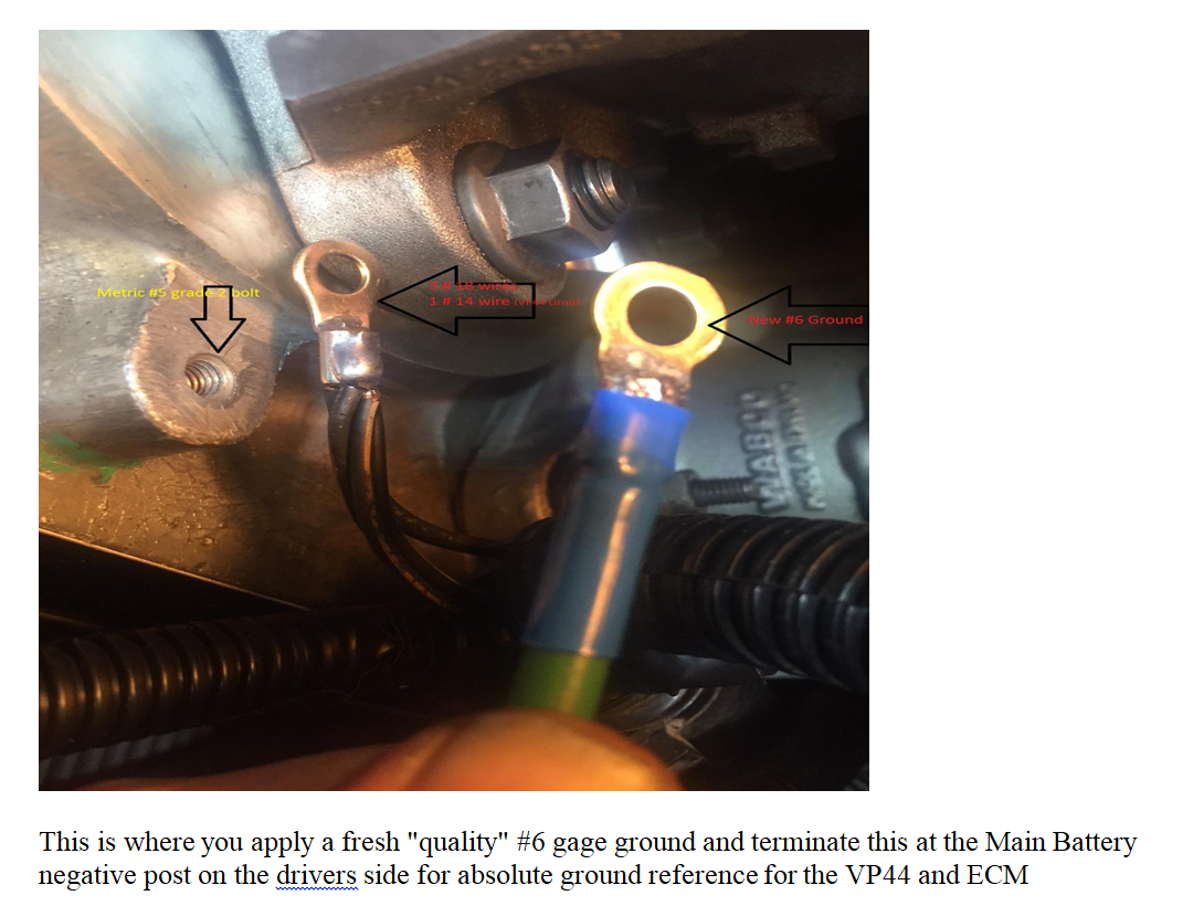
Correction - This moves ECM, VP and grid heater relay grounds from the right battery to the left battery. From W-T: John
-
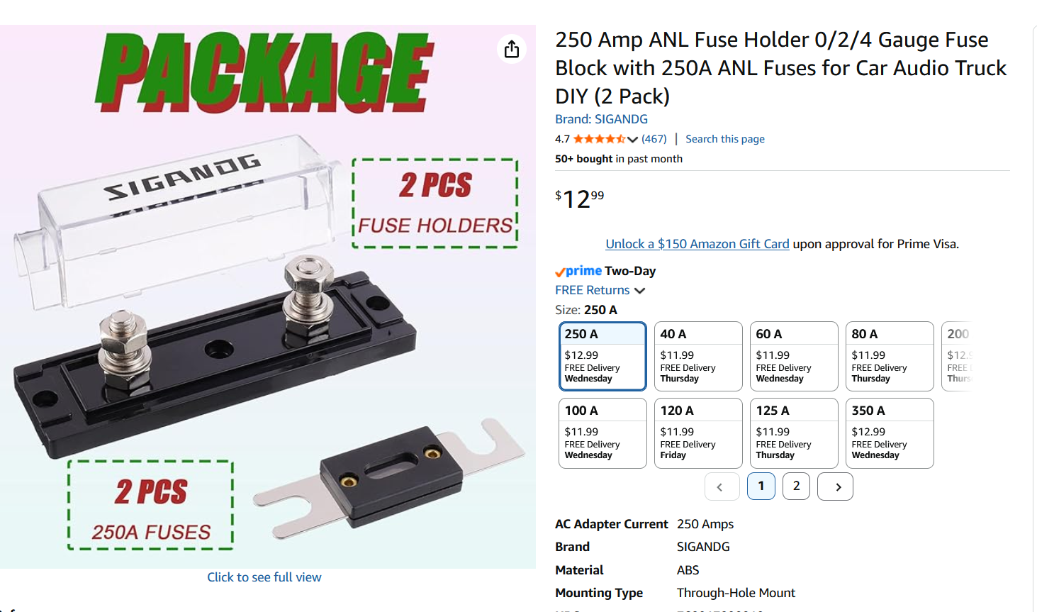
The photo below shows a 250 amp fuse and fuse holder similar to the style of fuse that I used. My fuse is 150 amp and has been reliable for over 3 years and over 30,000 miles. John
-
The 140 amp fuse is not there to protect the alternator. It is there for safety reasons in case the alternator or alternator output wiring shorted directly to ground. A fire could easily be started from the large amount of stored energy available from two large batteries that would have a direct path to ground if the alternator output circuit was not fused. By adding a non-fused second output wire, you are contributing to the potential for a fire. Personally, I would remove the old alternator output wire to the 140 amp fuse. I would run a single wire of the correct diameter through a suitable 250 amp fuse to the passenger side battery. The W-T Ground Reference mod wires the alternator output to the passenger side battery as part of the rewiring procedure. John
-
Then fill your radiator 50/50 (water/oil) so the o-ring will stay well lubed! .... just kidding! I do understand that you are trying to make something better. John
-
My radiator drain plugs are and have been the threaded plug style, too - I just incorrectly called it a petcock. What I have observed is that antifreeze does not make dynamic o-ring seals slippery like oil does, in fact antifreeze is kind of grippy. This is one of the reasons why water pumps use mechanical face seals. Years ago I took one of my drain plugs apart and cleaned it and after reassembly it didn't perform any better. I never really worried about the difficulty turning the drain plug because 99.9999% of its life is spent as a static seal and it never leaks. John
-
The radiator drain plug can be removed, but I probably would not do it. There a thick o-ring seal inside that the plastic petcock shaft fits through. The o-ring elongates because of friction while turning the petcock which in turn makes the petcock difficult to rotate. I find that if I rotate the petcock a little bit in each direction while opening or closing, it performs a little better. I have never broken one, but my brother-in-law has broken two. To my knowledge, there is no drain plug on the engine block. John
-
From Geno's Delphi Series 680 description: The Heavy Duty replacement steering box is a 16:1 ratio. The benefit to you: effectively 3.5 turns from lock-to-lock compared to 4.5 turns. I purchased and installed an new (not rebuilt) Delpi 680 series steering gearbox (part# BO800120) in 2015. It is a good steering box, but the ratio wasn't as advertised - the one I received was exactly 4 turns, stop to stop (my old one was 4 1/4 turns). The strange part was that the steering felt much quicker than the old box - not just a little quicker. I contacted Borgeson company and was eventually able to talk to an engineer. After explaining what I was experiencing, the engineer commented that it was strange as there is only one part number for all the second generation trucks that it was used on. She said that she wanted to look into it and would call be back. Here is what I wrote in my maintenance log: New steering gearbox - 4 turns from lock to lock (expecting 3 1/2 turns). Contacted Borgeson - engineer representative Barbara said that there are two boxes made for this era of Dodge trucks. She said that one is a 14:1 ratio and the other is a variable ratio with the highest ratio in the center of steering. She said that both of the steering boxes are sold under the same part number and that the customer has no say in which steering box the customer receives. I told the engineer that I have no issue with the steering gearbox that I received and thanked her for explaining the differences. So, I got the variable ratio one and I do like the steering gearbox. So anyway, I don't think that you would be disappointed with that steering gearbox, but I just wanted to let you know that you may get something slightly different than advertised. I have currently logged 186,000 miles on the Series 680 steering gearbox and I am still pleased with its performance. John
-
Steps 1 through 3 are good. When checking battery cables, make sure there is no corrosion creeping into the cable under the wire insulation. This corrosion is difficult to see and it commonly happens with aged crossover cables. There a wiring modification called the "W-T Ground Reference" mod. If you have not done that, it is a good thing to do. It takes care of some potential ground issues on the driver side of the engine. This will not likely correct your issue but it is a prudent modification to do as quality ground circuits are necessary for reliable computerized engine control components. This could be a beneficial test for diagnosing. What you accidentally did is called a "wiggle test" in the automotive industry. Perform this test in various locations with a helper watching the dash while the ignition key is turned on, or while the engine is running. You just may quickly find your issue. John
-
Thank you for that information and the quick response. There should be some very helpful wiring diagrams in the manual. When you are checking connectors, be sure to inspect that there are no pins pushed partially back into the connector body. This sometimes happens and it is easily overlooked. Not sure of what work you are doing inside the cab, but there are a couple of locations for ground connections for dash components. You will want to find those grounds (shown in the manual) and ensure there is good electrical connection at those locations. You also should do a thorough inspection of all the main battery cables and connections, including the positive crossover cable. The alternator charges the driver side battery, but senses voltage (state of charge) from the passenger side battery. John
-
You listed your truck as 1998 2500. A 1998 truck has a 12 valve engine (P7100 injection pump), a 1998.5 has a 24 valve engine (Bosch VP44 injection pump). Is your truck a 24 valve? 2 wheel drive? 4 wheel drive? So, the truck ran fine when it was parked and ran fine in September of 2024. What prompted you to send out the PCM for repairs? I am trying get a picture in my mind of the time line of what was wrong and when it was wrong, and what you did and why did it, as you progressed. As in,"a new battery", not "a different battery"? Are both batteries connected? Are both batteries the same model and the same age? You can download this 1999 service manual (assuming your truck is a 1998.5 year). John
-
Need more detail on the truck history and sequence of occurring events. Was the truck running fine prior to being parked for a few years? Was the PCM repaired before or after the truck was parked? You mentioned, "PCM was sent out and rebuilt, signs of over-voltage." What was the over voltage value? Was the truck parked inside or outside for the years it was parked? If outside, rodents could have been chewing on wires. Do you have a repair manual to use for wiring diagram information? Please provide as much detail as you can. John
-
Were you trying to save money on the recycling charge for used coolant? A few years back, I patiently filled my diesel tractor with five gallons of gasoline from a five gallon container. Ya think I should have noticed the vaporous odors of gasoline? - Nope. I started to drive the tractor and noticed that the engine idle was fluctuating. I figured it out and shut down the engine. Fortunately, no harm was done. Stuff happens. I think you are probably okay. I would monitor engine coolant for leaks and periodically check the engine oil condition for moisture. After you have re-established the coolant mixture ratio and the coolant level has stabilized, then monitor the overflow reservoir for normal changes in volume (cold engine vs warm engine).
-
P1682 - Charging System Voltage Too Low P0217 - Decreased Engine Performance Due To Engine Overheating Condition The two codes above match your symptoms. The P1693 is of no concern as it is considered as a companion code - meaning that a related code is set in another computer module (ECM, PCM). Sounds like you have an OEM style engine mounted lift pump (left side of engine). That particular lift pump location is noisy and raspy sounding. Not the best design as the lift pump has to "lift" fuel from the fuel tank as opposed to frame-mounted lift pumps or in-tank mounted lift pumps that push fuel through the system. After the coolant leak is repaired, then you can check if fuel is present at the VP44 by doing the bump start test. Do you have a means of checking for and clearing DTC's? John
-
First, I would like to commend you on an excellent first post. Lot of relevant detail there. This is not a serious issue. Likely there is a small leak in the low pressure part of the fuel system. Fuel may not leak out, but air can leak in when the truck isn't used for several days or weeks at a time. It takes a while for the lift pump to prime the system, consequently a delayed start. This issue does need attention, but it is not a priority at this time. When you say "bottomed out", was the voltage gauge pegged to the low side or the high side? Since you had a major loss of coolant, the temperature gauge was probably reading correctly. The coolant spraying all over the right side of the engine may be causing an electrical problem. I would first concentrate on getting the coolant leak repaired. If you fill the radiator and cannot detect a coolant leak, then it is best to test with a radiator pressure tester. Many auto parts stores have a loaner tool, or a rental tool program that may work for you. Does your truck have a fuel pressure gauge for the lift pump? Is the lift pump located in the factory engine mount location? You should be able to hear the lift pump run under the conditions listed below: Key in the "On" position - lift pump runs for 1/4 second Turn key into the "Start" position just briefly ( a bump) and then let go - lift pump should run for approximately 20 seconds. John
-
That will be quite the project. Just curious, what are you going to do with the front suspension for the additional engine weight? John
-
One more thing to possibly verify, if you haven't done so already. Temporarily jumper an LED test bulb to the wire at pin #7 at the VP44 (the 12 volt supply from the fuel pump relay). This bulb should always be lit while the engine is operating. If and when the engine dies, note whether or not the bulb stays lit. If it stays lit, then at least you know the wiring and fuel pump relay are working properly. Interesting regarding the reduced frequency of the symptom after adding two-stroke oil. Could be something to it, or just coincidence. You have done a lot of work trying to figure this out, so I personally would not draw any conclusion just yet. John
-
Here are some threads to peruse that may offer some insight. I have performed both mods about 1 year ago - well worth my time and expense. John
-
From the FSM. The torque for the end yoke nut is 470 ft/lbs. John (10) Check bearing rotating torque with an inch pound torque wrench (Fig. 54). Pinion rotating torque should be: • Original Bearings: 1 to 3 N·m (10 to 20 in. lbs.). • New Bearings: 2.8 to 5.1 N·m (25 to 45 in. lbs.). (11) If rotating torque is less than the desired rotating torque, remove the pinion yoke and decrease the thickness of the solid shim pack if greater increase shim pack. Changing the shim pack thick- ness by 0.025 mm (0.001 in.) will change the rotating torque approximately 0.9 N·m (8 in. lbs.).
-
So, are you saying that this "return to tank" is fuel return from the FASS lift pump, not the VP44? Just want to understand correctly what you are saying. If this is the case, it would seem that there could be a restriction in the return fuel line from the FASS lift pump. John
-
Can you give more detail as to what this is about. I am not sure what it or how to interpret what you did. Thanks for the update. John
-
Good idea posting the video. I listened to it several times. To me, it sounds as if the engine fueling is being momentarily switched off (no fueling, falling rpm) and then a split second later switched back on (fueling hard, to catch up to idle speed). It doesn't sound as if a heavy load is being placed upon the engine. As time progresses, each time the fueling is switched off, the duration (off) seems a bit longer until finally it cannot catch itself, consequently the engine dies. A most unusual problem. There is an ASD relay (automatic shut down) that is tied into the controller on the VP44. Blue Chip Diesel talks about this. If pin #5 (VP44 controller) has voltage present, fuel will be shut off. Supposedly, the ASD relay is a fail safe that protects the engine (such as when no engine rpm is sensed by the cam / crank sensor). The ASD relay (#59) is located in the PDC. You could swap it with the AC relay to see if it makes a difference. Also, Blue Chip Diesel mentions that some people cut the # 5 pin wire on the VP44 controller. John https://www.bluechipdiesel.com/runningtests
-
Good information on your first post; however, I am not sure what a "hiccup" means - could you elaborate on that description a bit more? In the meantime I will refer to "hiccup" as a symptom. If I understand your symptom correctly, it only happens a few seconds AFTER the transmission is shifted into gear - never right when it is shifted into gear. Is this correct? Trying to figure out if this is a transmission related symptom or an engine control related symptom. Also, are you saying that this same symptom occurred 3 years ago along with a P0216 DTC? Just confirming. The P0216 code concerns me. Is the mechanical set screw for the throttle cable secure? Have you confirmed that the idle validation part of the APPS is working properly? John


