


Tractorman
Yearly Subscription
-
Joined
-
Last visited
Everything posted by Tractorman
-
Have you checked for any DTC's? Is fuel pressure where should be (lift pump pressure)? What are the conditions of your battery cables (including the crossover cable) and battery connections - both positive and negative? You may want to get the tuner completely out of the system to help diagnose. Please give some history about the truck - miles and years you have owned it and what you have done to it, etc. - John
-
What tire size are you running? - John
-
That makes sense regarding the 9 cm2 housing and could very well be his problem. - John
-
What was the engine rpm and boost pressure when the EGT reached 1500°? I presume your observations were done with an empty truck. I am curious as to why the high EGT's. I always thought that the HE351CW turbo was a good upgrade - just what I have read. - John
-
I agree, the concept seems sound. If the added bearing is centered and well anchored, then it should be beneficial. It seems like you may have the equipment and the skills to do that. Let us know how it turns out if you decide to make the modification. - John
-
I haven't done your particular job, but I think you have to line up two items - the splined input shaft and the tabs (or cutouts) for the pump. Usually the shaft engages first (could be the opposite), then you need rotate the converter (with no axial pressure) to find the tabs for the pump engagement. Just an educated guess. - John
-
With stock sized / near stock sized tires and stock suspension height - I say no. I am not sure that there would be any benefit even with bigger tires and raised suspension. I installed a steering brace years ago and I have since removed it. The one thing that bothered me about the steering brace was that there were only two set screws (90° apart) for centering the bearing on the the Pitman shaft. That never made sense to me - it always forced the bearing to one side which in turn forced the Pitman shaft to one side, and the set screws would never stay tight. That did made sense to me. I would think that three set screws at 120° apart would have allowed for accurately centering the bearing and would have kept the set screws tight. - John
-
Sounds like you have your work cut out for you. Just be patient and correct all of the previous owner's careless wiring. Chances are that there is nothing wrong with the expensive components - just poor electrical connections to them. Let us know when you get the problem resolved. - John
-
Keep us posted...., - John
-
To aid in troubleshooting, it may be worth your while to remove the Quadzilla completely from the system for awhile - at least until you get this problem resolved. The Cummins sensors are very reliable. In fact, I still have all of the original sensors in operation on my truck. You said that you were going to check for codes with a Snapon scanner after you put the pump back in. Has that been done? - John
-
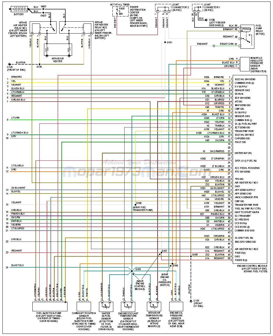
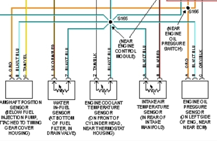
Since all of your codes point to a 5 volt supply issue, I would definitely check out the 5 volt supply and ground. Also, I would check the supply voltage and ground for the ECM and look over the general condition of the electrical system (battery terminals, cross over cable, grounds, etc.) Splice 165 (a problematic splice) is part of the grounding circuit for the ECM and other sensor grounds of the 5v system. Auto Computer Specialists (look in the Vendors section on this site) rebuilds ECMs . New ECMs are not available. Lift pump cycles 1/4 second with key in "run" position, approximately 25 seconds in "bump start" position. Just round numbers. - John
-
No fuse, but you can simply disconnect the two heavy wires that feed each intake heater. Disconnect them at the positive terminal on the driver side battery. I will repeat what I said in one of my previous posts, "The Bosch and Denso alternators are of excellent quality." The same goes for the Denso Starters. Unfortunately, many people don't realize the value of these OEM alternators and starters in terms of a long dependable life. The first sign of an electrical problem has them purchasing a cheaper re-manufactured alternator or starter from a chain auto parts store. From there, it usually goes downhill. Those re-manufactured components are usually of mediocre quality at best. The worst part of the transaction is that the truck owner is giving up a quality component in trade for a not-so-quality component under the guise of "lifetime warranty". So, either one of two things are happening in your case. You are getting poorly re-manufactured alternators, or you have a serious electrical problem that needs to be addressed. I would recommend checking the condition of all your battery connections - positive and negative. And, check the condition of the crossover cable. Just because an electrical connection is tight does not mean that the connection is good electrically. There could be corrosion that is not visible until the connection is taken apart. - John
-
Have you used a quality scanner for checking codes? Not all scanners are equal. Or, have you used the ignition key method to read codes in the odometer? - John Since your problem is intermittent, it is possible that the pump could be defective and still pass the test. Don't dwell on this, but don't disregard it, either. Have you re-checked your work related to the W-T wiring modification? - John
-
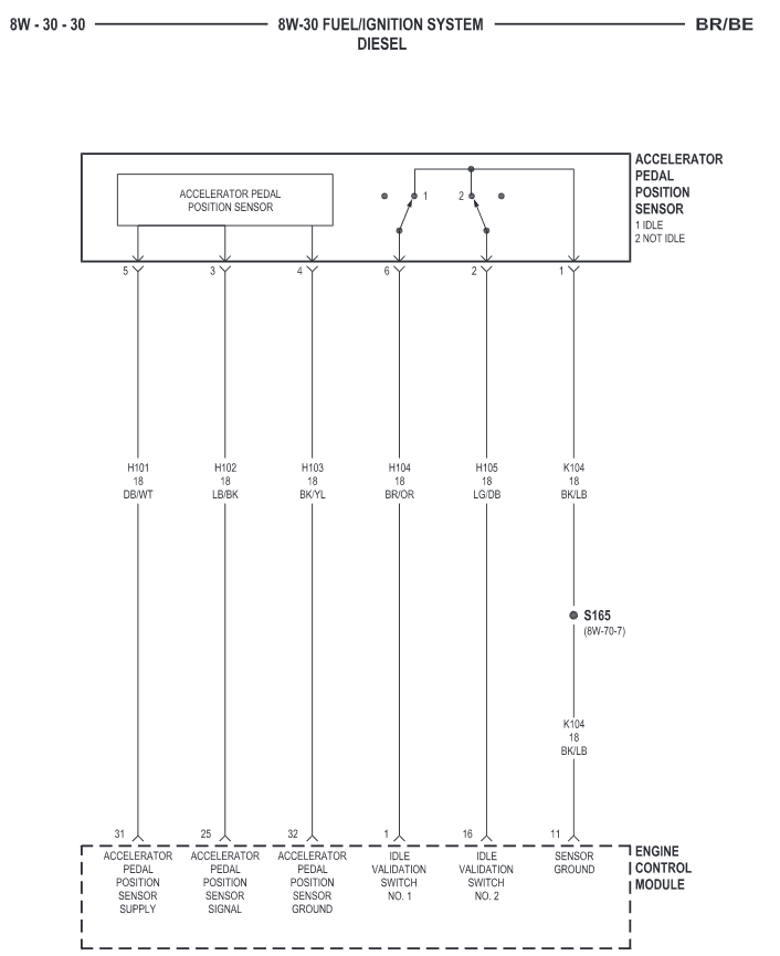
I would do this step, first. It would be good to know whether or not a false signal is being generated at idle. Since the DTC states, "Idle Validation Signals Both Low Problem detected with idle validation circuits within APPS", I would double check the wiring condition and connections from the ECM to the APPS - and, maybe try another APPS, if you have one available. Also, I believe that you said you did the W-T wiring modification. If so, re-check your work regarding Splice #165 - the ground for the APPS, ECM, and other sensors. - John
-
P0222 (M) Idle Validation Signals Both Low Problem detected with idle validation circuits within APPS. I would definitely find out why you are getting this code. If the ECM does not get a signal for idle validation, then the engine rpms will not go to idle. Which APPS are you using now - OEM or TImbo? Either way, you could try adjusting the mechanical stop where the APPS is located in the engine compartment. Back it off an extra distance to ensure the throttle will activate the idle validation switch that is built into the APPS. I seriously doubt that. An injector misfiring would likely cause a miss or a timing knock. Engine oil feeding a cylinder wouldn't allow the engine to shut off immediately when you switched off the ignition. I think the P0222 in telling you something. Double check all of the pin conditions in the connector to the APPS. - John
-
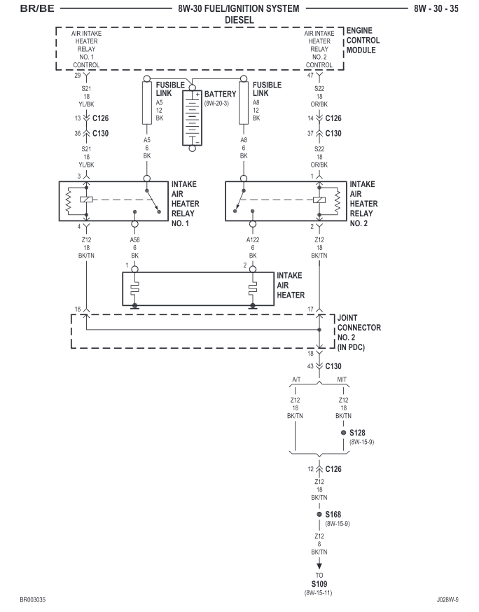
I just used a switch that I had laying around. A push button momentary switch would work well. Place it where it is convenient to use. The switch can be light duty, as it only operates the coil portion of the intake heater relays (less than 500 milliamps of current). I disconnected terminal # 1 (OR/BK wire) on relay # 2 and terminal # 3 (YL/BK wire) on relay # 1. I sealed and taped the ends to protect them for future use. I provided a light gauge wire (18 gauge) from an unswitched source, through a 5 amp fuse, and then to the momentary control switch. From this switch, I continued with the 18 gauge wire to the coils of both intake heater relays. Wired this way does set DTC P0380 and P0382, but it does not illuminate the MIL. From this point on, you can be the boss and use the intake heaters when you feel it is necessary. The ECM controls when the intake heaters operate. If the ambient air temperature falls below 60° F, then the ECM will command both intake heaters to operate for a determined amount of time when the ignition switch is turned on. After the engine is started, the ECM will cycle the intake heaters (one at a time alternately - called post cycling) until either the vehicle speed exceeds 20-25 mph, or engine coolant temperature reaches a specific value. The air intake heaters exist primarily for emissions and occasionally they are needed to assist in starting a very cold engine. - John
-
Give us some repair history on your electrical system. How old are the batteries? Have you verified that all battery and ground connections are good? How about the crossover cable? Have you done the W-T wiring modification? OEM wiring charges the driver side battery - the W-T wiring modification charges the passenger side battery. I personally don't trust over-the-counter re-manufactured electrical parts. They can be problematic regarding quality. If I wanted an alternator or starter rebuilt, I would use a quality Auto Electrical shop in the vicinity. The Bosch and Denso alternators are of excellent quality. The Bosch alternator (the original still controlled by the PCM) on my truck is pushing 400,000 miles with only replacing alternator bearings and brushes. When you do replace this alternator (I think you already have), be sure to monitor voltage at both batteries, don't just rely on the dash voltmeter. I would disconnect the grid intake heaters temporarily just to help with the diagnosis. It is not necessary to take any of these precautions. Even when you do plug it in overnight, the grid heaters will still post cycle for a period of time after the engine is started. A new Bosch or Denso alternator will easily last 200,000 miles under these conditions. Even though it is not necessary, I have installed a manual momentary switch to operate the grid heaters on my truck. I did this to reduce the electrical load on the alternator and because grid heater operation isn't necessary 90 per cent of the time for starting the truck, or for post cycling after the engine is running. - John
-
Before replacing the APPS, you wrote: After replacing the APPS with a Timbo unit, you wrote: Has the "skipping and bucking" disappeared? What horse power injectors are you using? As @Great work! mentioned, high horse power injectors can cause hunting. Different torque converters can apply different engine loads when the transmission is placed into gear. - John
-
Great detail on your reply. Another thought. Have you tried using the key switch to read codes in the odometer display? 2001 is a questionable year for using the key switch to read certain codes. Some 2001 models read the PCU only, and other models read PCU and ECU. If your truck happens to read both, maybe you can see the companion code in the ECU. If your truck shows both, just be sure to be patient and wait for both PCU and ECU to say "DONE". Regardless, it does seem there is a hidden ECU code that needs to be seen. Just don't know how to get there. - John
-
Do you know if your VP44 pumps were refurbished - as in a new PSG vs. refurbished PSG, and was the pump run and the PSG calibrated to the pump on the Bosch 815 test stand? - John
-
On this ECM, you say "truck runs". Does this mean everything is normal and the truck runs good? Just a 1693 code? Does the code set the MIL (Malfunction Indicator Lamp)? This could be normal lift pump voltage while the engine is cranking. The ECM reduces voltage to the lift pump by using pulse width modulation during engine cranking to prevent possible hard starts under heat-soaked startups. The ECM supplies full voltage to the lift pump after the engine is running. Is you lift pump fuel system completely stock? Does the ECM drive the lift pump directly? - John
-
He has posted as recently as last Wednesday, the 21st. - John
-
Well, that's a bummer! Any codes? You could hook up a scanner and monitor the throttle position on the display. Drive the truck and when the symptoms occur at idle, see if the per cent of throttle changes on the display, or if it remains steady as it should. I think that you may still be getting an electrical interference of some kind. I don't know much about the ECM operation, but I think the ECM has the capability to monitor and weed out false signals. However, if too many false signals are being sensed in a specific amount of time, the ECM may consider the signals to be valid. The APPS provides one of those signals. It may be worth a try to leave the ignition switch in the "Run" position and slowly depress the throttle to the floor one time and release. Turn the ignition switch off and then start the engine. This is not a fix, but if there is electrical interference with the APPS, then the symptoms may disappear for awhile. This may help to diagnose what is really going on. - John
-
P0122 (M) Throttle Position Sensor Voltage Low Throttle position sensor input below the acceptable voltage range. The "M" (Malfunction Indicator Lamp) may or may not light dependent on EPA requirements. This definitely falls in-line with a dead pedal symptom when cruising at a common road speed under a light throttle - worth checking out. The OEM style APPS can get a worn spot on the potentiometer when driving at repeated highway speeds over long periods of time. How well did the engine run on your 30 mile "limp"? The VP44 internal vane pump (called "feed" pump by Bosch) would still bring in plenty of fuel through the dead lift pump as long as there was not a severe restriction inside the dead lift pump. If the engine performed normally on the 30 mile trip, then there may be no harm done to the VP44. Can't really offer any help with the hanging injectors. What injectors are you currently using and how many miles on them? - John
-
Have you checked for trouble codes? If so, what are they? Most of the time (not always) codes will show up when a VP44 injection pump begins to fail. - John


