


Tractorman
Yearly Subscription
-
Joined
-
Last visited
Everything posted by Tractorman
-
It appears that you have an OEM style APPS. It appears that there is a hand throttle connected to the throttle (in your photo). Make sure that the hand throttle is not interfering with the idle stop adjustment. The link below should help with checking the operation of the APPS. - John
-
I am assuming that you used a Mopar APPS to communicate with the a Cummins ECM for the era of engine you put into your F250. The idle validation switch is part of the APPS. When the throttle is released, the mechanical throttle stop should allow for the idle validation switch inside the APPS to be activated. This action removes all inputs to the ECM and allows only the ECM to maintain idle rpm. When you installed this engine and controls into your F250, did you use the ECM, PCM, APPS, etc. from a sacrificial Dodge Cummins truck? It is hard to offer help in your situation, mainly because I don't know how your conversion was done or what parts were involved. - John
-
Since you are getting several DTC's that are all over the map and your engine is not an OEM application, I would double check the integrity of all related wiring connections (both positive connections and ground connections) that you performed to make this conversion work. Also, make sure that the APPS home position at idle activates the idle validation switch. An engine idle stop that is mis-adjusted could provide some of the symptoms you mentioned. You could disconnect the APPS and check for smooth operation using an ohmmeter and also check the operation of the idle validation switch at the same time. - John
-
I would double check Pin #6 (ground) test. This test should produce a steady voltage. I would use a test lamp with an incandescent bulb, if possible. This will place a small electrical load on the circuit being tested. Pin #6 is connected to Splice #168 which splices into two ECM grounds and an engine block ground. Splice #168 has been know to be troublesome. So, try retesting Pin #7 to Pin #6 with a test lamp - ignition on for the first test, engine cranking for the second test. The lamp should dim slightly, but remain steady for the engine cranking test. If the test fails, then keep one lead of the test lamp on Pin #6 and connect the other lead to a battery positive post. Note the results of the test. Are there any DTC's stored? If so, knowing what they are could help with troubleshooting. Your high mileage injectors should be replaced. The injectors are not the cause of your no-start, but you have gotten a good service life from them - time to replace them. Using a multi-meter to check resistance at connectors is a common practice, but it has its limitation, i.e., a single strand of wire in multi-strand wiring maybe the only connection, which can falsely indicate that a circuit is good. This is why I use a test lamp whenever I can - to place a small electrical load on the circuit during the test. - John
-
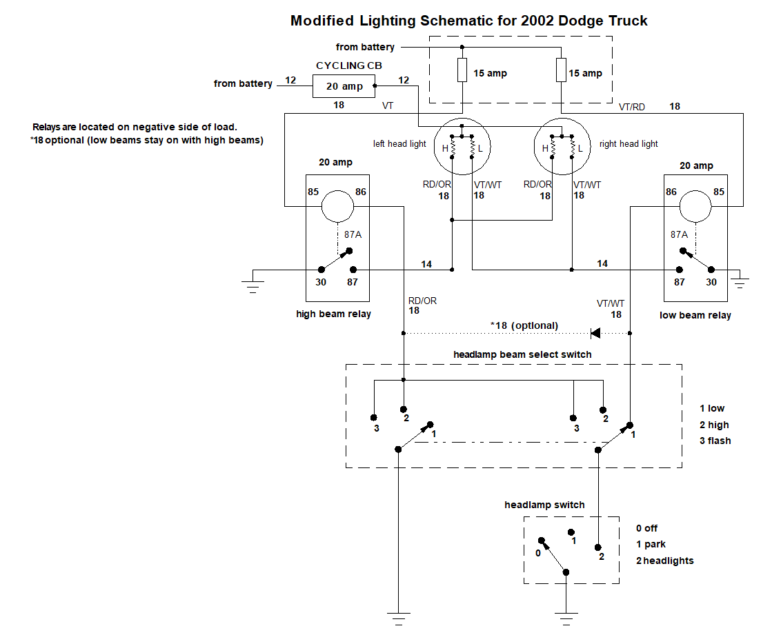
I use software called DesignCad 2018. It started out as Prodesign in 1985, when I first started using it. . i think the filament works as a resistor to limit the current draw. Still this set up causes a constant drain on the battery when truck is off because it is in fact shorting at the headlight bulb. There is no short to ground when the headlight switch is turned off and headlight beam selector switch set on low beam. It is just battery voltage potential with an incomplete path, so no current flows. - John
-
I think you would be correct. Sounds like you will have a new relayed headlight system that you will be happy with, soon. The diagram below shows how I wired relays into the existing 2 headlight system when my truck was new. Later, I modified the diagram for a Sport headlight system. The numbers by the wiring represent wire gauge. Years ago, I lost my high beam indicator lamp - I always thought that it burned out, but now I am wondering if I sabotaged that circuit! - John
-
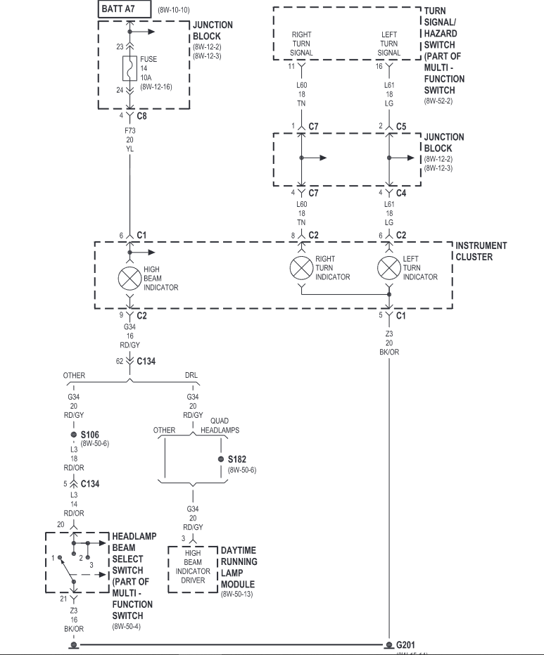
I think that "someone" is correct, although I don't consider it to be a fault. The stray voltage is coming from the high beam bulb. That bulb is fed by Fuse #14 (10 amp from battery) in the PDC. That bulb is grounded when high beam is selected. When low beam is selected, the bulb is not grounded - hence, voltage is present at the RD/OR wire via Fuse #14 and the high beam indicator bulb. So, I think your OEM headlight circuit is working as it should. - John
-
No judging at all - you have to use the tools that you have on hand. Appreciate you answering all the questions. Just double checking here - "bulb" is singular - both bulbs need to removed for the test, otherwise back-feeding will occur through the bulb filaments. Also, with your relay adapter harness removed, is the wiring harness now completely stock? This sounds like stray voltage to me. This can happen when a wire both ends of a wire a renot connected in a particular switching operation. It is one of the reasons that I use a test light with an incandescent lamp when testing these circuits. The imposed electrical load from the incandescent lamp eliminates stray voltage from the picture. Multi-meters will easily read any voltage present - even if it is stray and is not backed. The fact that the voltage disappeared when high beam was selected indicates the circuit is working - maybe not the best it could be, but it is working. The .5 voltage drop to ground when the high beam is activated sounds like a poor ground connection, but should not be causing you any problems. - John
-
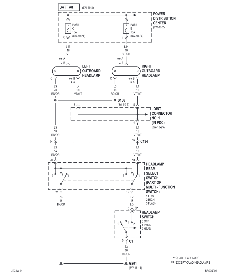
I am still not sure where you are getting Pin #1, #2, and #3 information from. Regardless, the wire colors you mention are for the right side headlight. I am going to use the FSM wiring diagram for reference. RIght side headlight: ** A - VT/RD - 15 amp hot fuse from PDC ** B - VT/WT - low beam wire to dimmer switch, then headlight switch, then to ground C - RD/OR - high beam wire to dimmer switch, then to ground Left side headlight is the same except that **A is VT and has a separate 15 amp hot fuse from the PDC. What does "everything" mean? - both headlight connectors? dimmer switch, headlight switch? Have the bulbs be removed? I would not use a power probe for testing. I would use a test light with and incandescent bulb. I would leave everything connected except for the left and right headlight connectors. Both connectors should have the 9004 bulbs removed. I would turn the headlights to the "ON" position and have the dimmer switch selected to low beams. **A - test lamp clamped to battery ground and test lamp probe connected to **A. Test lamp should light (power from 15 amp fuse). **B - test lamp clamped to battery positive post and test lamp probe connected to **B. Test lamp should light (ground through headlamp switch via dimmer switch). C - Activate high beam switch. Test lamp clamped to battery positive post and test lamp probe connected to C. Test lamp should light (ground through high beam selector switch. Just for general information (and maybe you already know this), but the headlight switching is all in the ground circuit. When the bulbs are removed, the only voltage that can be present is at terminal **A at both headlight connectors. The remaining terminals will be either open or grounded depending on position of switches. Hopefully, I have not made any errors - feel free to correct them if I did. - John
-
I am a bit lost with your explanation. I don't see any of the terminal pin numbers that you refer to, so I don't know which connectors you a referring to. Also, the type of relay you are using (not part of the diagram below) isn't identified. The headlight wiring diagram below is for a 2002 Dodge Ram (probably the same for a 2001). The "double asterisk" by each headlight represents the connection to a "non Quad" headlight system. You will note that terminal "A" at each headlight is always hot via two separate 15 amp fuses in the PDC. Low beam is selected by grounding terminal "B" of the headlight via the multi-function switch and then the headlight switch. High beam is selected by grounding terminal "C" of the headlight via the multi-function switch. It will help if you show the type of relay that you are using so that the wiring can be understood easier. - John
-
The one thing that hasn't been mentioned in this topic is the "break in" procedure for high performance clutches, so I thought I would mention it. I just installed a South Bend 1947-OK-HD single disc organic clutch (450 hp/900 torque) in my truck. Required break-in instructed by South Bend is mostly city like driving with lots of starts and stops - empty truck, no full power for 500 miles. This results in the best holding power quality for the clutch and lasts for the life of the clutch. Any slipping of the clutch (after engagement) during break-in will reduce the holding torque of the clutch up to about 200 lb/ft - permanently. So, no matter which high performance clutch is used, the break-in procedure provided by the manufacturer should absolutely be followed. I just returned from a camping trip with my 19 ft travel travel - gross combined weight around 12,500 lbs. When I started the trip, I only had about 50 miles of city driving on the new clutch - nowhere near the 500 miles. I was very concerned about unintentionally slipping the clutch under load. I thought I had a lot of leeway because my truck only develops just over 600 lb/ft of torque - RV 275hp injectors and a mild Smarty S03 tune. I was wrong. It didn't slip climbing up long passes. It slipped when I pressed the cruise control resume switch at 60 mph with cruise set at 65 mph - definitely caught me by surprise. The engine raised about 200 rpm for less than 1/2 second. Hopefully, I haven't done any permanent damage. The return trip was uneventful, but I was a little more careful. So, whichever clutch you get, be sure to follow the break-in instructions. - John
-
Now I see why you are concerned about the high mileage original head gasket. When I return from a camping trip (leaving tomorrow) in about a week, I may post your question on the TDR (Turbo Diesel Register) and see what kind of response I get. I have settled for RV275 hp injectors and a mild tune on a Smarty S03. - John
-
Thanks for posting the video - it definitely sheds a better light on your project. The fellow with the beard seems to know a lot about fasteners. What I have learned about fasteners over the years aligns exactly with what he is saying. Good information. I can see why you are pursuing this. Back to your project - if enough oil was left in a bolt hole, a hydraulic lock could occur when the fastener is nearing the bottom of the bore. Since oil is virtually non-compressible, the oil would be forced around the threads (spiral leakage). That could be why the fastener wants to keep turning as you near maximum torque. Did you have any issue with the washer size in your application? Just curious, as I may consider doing what you are doing. Also, are you running stock power? If not, what power level? - John
-
I think there are too many variables in what you are trying to accomplish to make an accurate conclusion as to whether or not you will prolong the life of the head gasket. One variable is that two bolts of same thread diameter and hardness, but different shank diameters (as you have noted) could have performance differences. Those differences could affect the elastic limits of either bolt. So, while both bolts may provide an equal clamping force, one may be able to maintain its clamping force through a longer clamping stretch distance, which would perform well in a large thermal expansion / contraction range. There is no way to have that information just by looking at two different bolts. Another variable is that you are using a maximum torque specification with a torque wrench while Cummins is using a "torque to angle" specification to reach a final torque. These different applications could have different clamping force results. A third variable is that one has no way of knowing the rate of deterioration or the actual condition of the head gasket material at any given point in time during the engine's operational life. Additional clamping force may offer no help. I have the same concern as you regarding the life of my head gasket (I'm at 389,000 miles), but I have decided to run as is until I see the symptoms of a head gasket failure. It may not be the best decision, just my decision. Of course, I would also like to mention that I certainly have no expertise in this subject - only my experiences. So, when my head gasket fails and yours doesn't because you performed some pro-active measures, be sure to let me know! - John
-
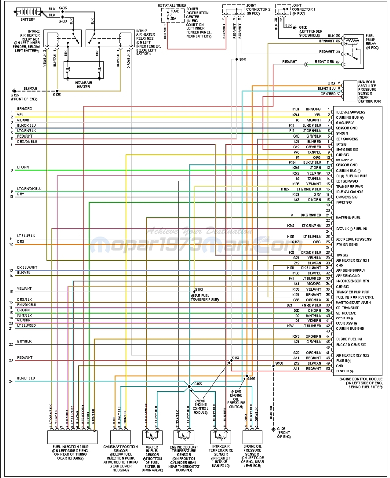
To muddle your issues even more, there may not be a crank position sensor on your engine. Somewhere around the year 2001 model engines, Cummins stopped using a crankshaft position sensor began using a cam position sensor only. If this is the case with your turck, that sensor is located on the timing gear cover housing just below and close to the bottom of the VP44 injection pump. If your engine has a cam sensor, it will have 3 wires attached. One for 5 volt supply, one for ground, and one for signal to ECM (terminal #9 on the ECM). Sometimes the sensor can be faulty - sometimes the wiring or connector can be faulty. Also make sure that all battery connections and grounds are clean, tight, and in good working order. - John
-
I think it should work. - John
-
Something looks different in the bottom photo versus the top photo. It appears that you made a large cavity in the firewall? Sometimes photos are deceptive - I may not be interpreting the photo right. Are you still going to add a heat deflector on the turbo elbow? - John
-
I would think that there would be very little engine movement axially. Torsional movement (left or right) shouldn't have any adverse effect. Maybe a combination of a heat shield and exhaust wrap would work the best. Modify the firewall to gain as much clearance as possible, wrap the exhaust, use the bosses to mount a heat shield. Wouldn't matter if the exhaust wrap contacted the heat shield. Just allow at least 1/2" inch or more between the heat shield and the firewall for air flow. Of course, these are just my thoughts - I have no real expertise - just my own experiences. From the photo it looks like the lower boss is the closest to the firewall. It would be this area that will need the most attention to gain more more clearance by modifying the firewall. The head of a heat shield mounting bolt would consume some of that clearance. - John
-
It might be hard to get an exhaust wrap in that tight of space to be effective. The wrap could contact the firewall under certain operating conditions. If it did, there would be wear on the exhaust wrap and the associated noise could be annoying. What about forming a heat shield to fit in the space without contacting the exhaust or the fire wall? It would be easy to monitor for effectiveness. An effective heat shield can dissipate a lot of heat. - John
-
One good reason to stay with the negative switching with headlights and fog lights is because the batteries and lights are in the same compartment - under the hood. This makes it easy to run a short hot fused wire directly to the the headlights or fog lights. Then the very long and circuitous route for the ground wire from the lights into the cab, through the various control switches, and then eventually to a ground makes it impossible to blow a fuse if a wire is unintentionally grounded after leaving the headlight or fog light. It reduces the ingredients for a possible fire. But, in the end, either way will work fine. - John
-
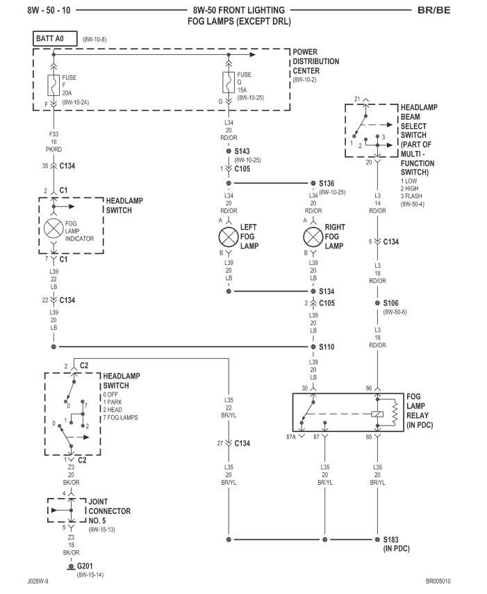
Thanks for the information. The wiring diagram below is from the 2002 FSM. I don't know if it applies to your 2000 year model truck. If by chance the wiring diagram is the same, then I would check the condition of the fog light wires that were cut and repaired. The 15 amp Fuse G in the PDC supplies battery voltage directly to the fog light. If a grounding wire leaving either fog light were unintentionally grounded prior to the fog light relay, then the fog lights would come on. - John
-
Need more info about your truck. Is your truck a standard 2 bulb headlight system or a 4 bulb Quad headlight system? Do you have factory daytime running lights (Canadian truck)? And last, has your headlight / fog light system been modified? Also, what year and model is your truck? - John
-
Excellent! - John
-
Sounds like a good approach. Good extra step your part for re-checking the valve clearance. I agree that a faulty injection pump likely would not isolate one injector. The only way it could would be if there was a problem in the distributor head or in the constant pressure valve for the injector firing #3 cylinder. I would think a problem there would show up while the pump was being operated on the test stand. Please let us know the results after you install the new injectors. - John
-
@01_Cummins_4x4, have you heard anything regarding your VP44 injection pump from Oregon Fuel Injection? I am assuming that you have talked to them about your engine idle flutter. - John


