


Tractorman
Yearly Subscription
-
Joined
-
Last visited
Everything posted by Tractorman
-
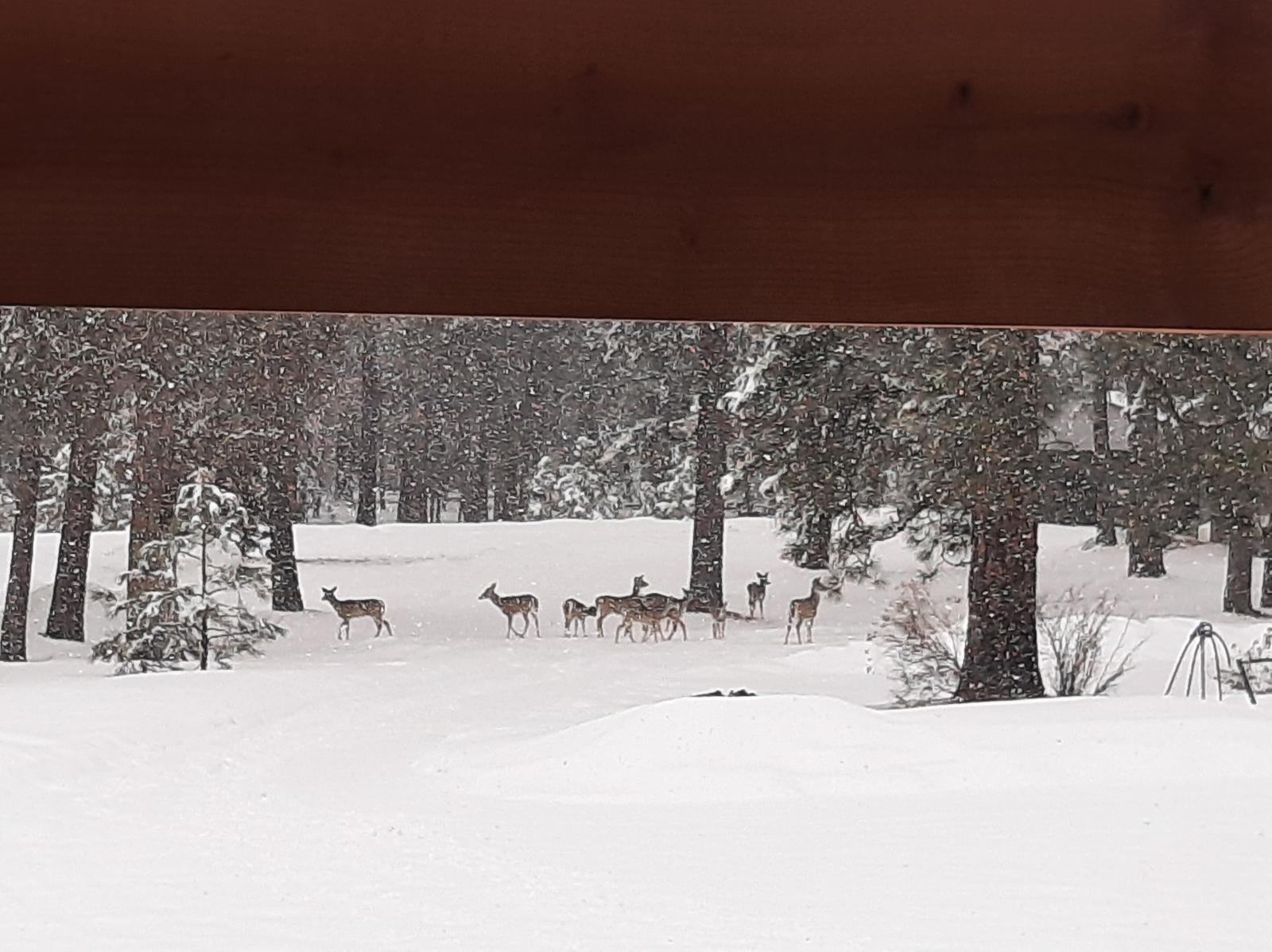
So far, we are on track for a late spring. The 10 day extended forecast is still showing below normal temperatures and snow showers for my location about 10 miles northwest of Baker City. Then it is forecast to switch gears for warmer, more seasonal temperatures. The photos below taken on 3-10-2023 (bottom) and 3-28-2023 (top) at my place (3,800' elevation). This is only my fourth winter here, but normally the snow is gone by the middle of March. There is still plenty of time for the snow to melt in the high country and (as @JAG1mentions), I will check out the area around Magone Lake early enough to make a decision on camping there. I am looking forward to seeing everyone wherever "there" ends up being. Just for information, Prairie CIty is at 3,500' elevation and Dayville is at 2,400' elevation. Prairie City has by far the best view. - John
-
They must be making better trucks now, 'cause before they just shut down by themselves, even if you made payments. - John
-
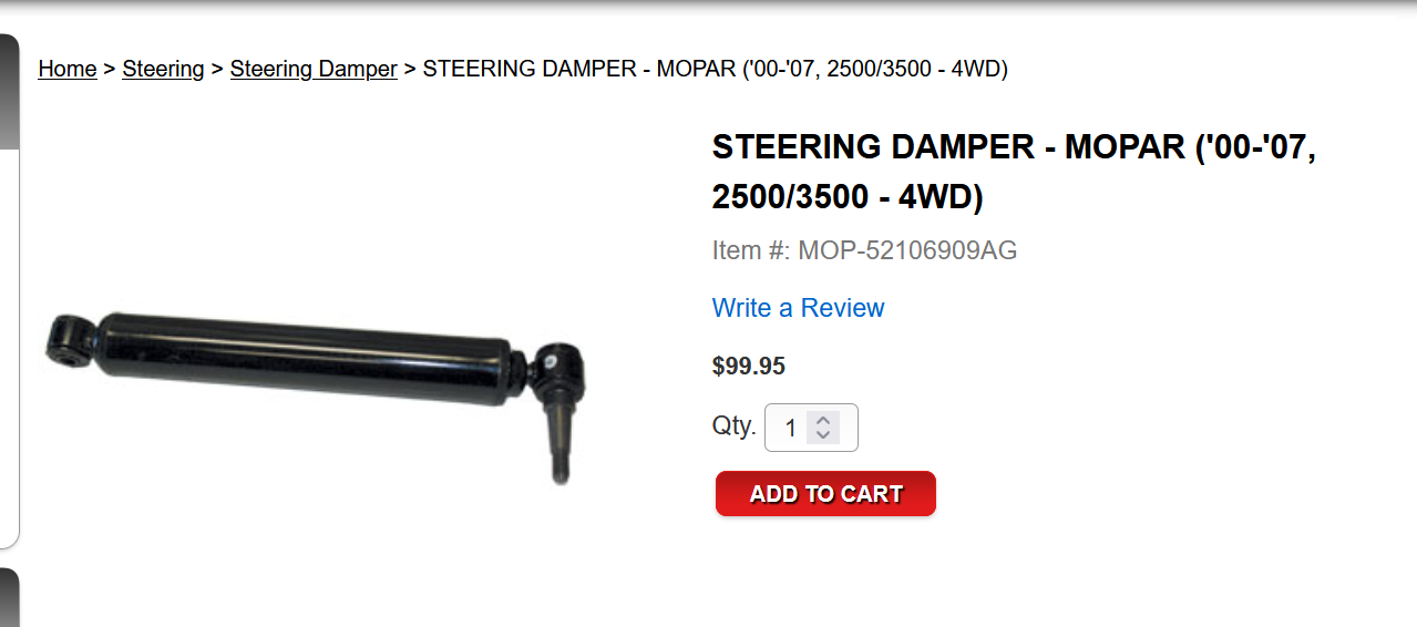
Not saying that this is the best steering damper, but this is the one I purchased from Geno's Garage. It is definitely more heavy duty than the NAPA one it replaced - 5/8" shaft vs. 1/2" shaft and a larger diameter cylinder. Also, I've never known Geno's to sell marginal products. - John
-
I believe 28 ft/lbs is the magic number for the fuel line connection at the head. I have never experienced any injector lines coming loose. - John
-
That's good news - you are probably fine. - John
-
Looks like you may have found the source of your problem. Hopefully, you have. When you remove the track bar, be sure to closely inspect the end that connects to the axle. If there is evidence of movement between the steel bushing inside the track bar and the mounting bracket ears, this means that the bolt was never tight enough. The bolt may have been tightened to the correct torque value, but it wasn't enough to clamp the brackets solidly to the steel bushing. There should be absolutely no movement here. If by chance the bracket ears are damaged from movement of the steel bushing, you will have to assess the damage. It will be even more difficult to get the right clamping force if the bracket ears are damaged. - John
-
I should give a bit more steering history on my truck. For the first 168,000 miles I was not happy with the steering - specifically poor steering return and I felt I had to constantly steer the truck into and out of curves as well as straight down the road. The truck would not track straight. So, after doing some research I decided to significantly increase the degree of caster. This one action gave impressive results - instant improved performance in steering return and straight ahead tracking. After a few days I then removed the steering damper just to feel the difference. On the highway there was very little difference, off-road I could feel the road in the steering wheel much more. Just for grins I left the steering damper off for the next 88,000 miles (5 years). Interestingly enough, the truck continued to handle well and I never had any indication of death wobble. (Just another piece of information that adds mystery to the actual cause of death wobble.) * 168,000 miles - set caster to positive 4 1/2° Remove OEM steering damper (still in good operating condition) * 256,000 miles - install a new steering damper (NAPA) I decided to re-install the damper for extra insurance against the chance for a death wobble occurrence for an aging truck. No sense in tempting fate. * 372,000 miles (yesterday) - replace steering damper with OEM (116,000 miles on NAPA damper - leaking and no resistance) Noted that the NAPA damper uses a 1/2" shaft and the the OEM damper uses a 5/8" shaft. In my case the OEM damper was still working as designed at 168,000 miles while the NAPA damper failed before 116,000 miles. @Doubletrouble, I am very interested to see what resolves your death wobble issue. - John
-
The resistance should be heavy in both directions. Also equally important is there should no change in resistance when changing direction (push, pull), not even a slight reduction of resistance. Coincidentally, my steering damper was showing a drop of oil collecting on it and occasionally dripping for the last couple of months. I ordered an OEM damper from Geno's and I installed it last night. The old damper moved 2 inches in either direction without resistance. - John
-
Well, now that the smoke has been released you can go ahead with your repair. - John
-
First, I have never experienced death wobble. However, I have read a lot about it and I do understand the concept of death wobble. If this were to happen with my truck, I would be just as concerned as you are. While you are pondering what to do, here is a good read on death wobble. https://www.thurenfabrication.com/pages/death-wobble-explained Just a couple of the usual questions - are you running stock tire and wheel size? And, is your truck still at the stock lift height? I personally think that the OEM track bar is of poor design. The sleeved bushing on the axle end is quality - the steering type ball joint on the other end should have been a sleeved bushing as well (like the third generation). This is one item that I would replace (with or without the death wobble). I did replace mine with a Rare Parts adjustable track bar - still a ball joint style, but a much larger diameter ball stud and socket. I have logged over 150,000 miles with that track bar and it is still doing fine, but as hind sight, I think I would have rather used the third generation adjustable track bar for reliability and ease of future replacement. If I were in your shoes, I would check every dynamic suspension and steering component for wear. Here's how I perform my checks. I rig my video camera (mobile phone) on a portable stand and make videos of each movable part. For example - a tie rod end: * The truck needs to be setting on a hard surface with the tires pointed in the straight ahead position. Place the camera near the tie rod end to be checked and start the video. Get in the driver seat and start the engine. Slowly (about 1 second per cycle) begin moving the steering wheel back and forth about 15° from center in each direction several times. This will put a significant load on each suspension and steering component. The video playback will show if the component is worn. A long time ago, I considered switching to the "T" type steering, but I changed my mind. After setting caster to a positive 4 1/2° and using the heavier track bar, my truck steers and handles far better than when it was new. The one thing that seems to stand out from people reporting death wobble is that the solution many times seems to be vague. After replacing many parts, the death wobble disappears. Many people report that the last component replaced is what cured the death wobble. I am not so convinced. Personally, I think that the cause of death wobble rarely comes from one single condition. That is why I think a close inspection of steering and suspension components is needed. - John (
-
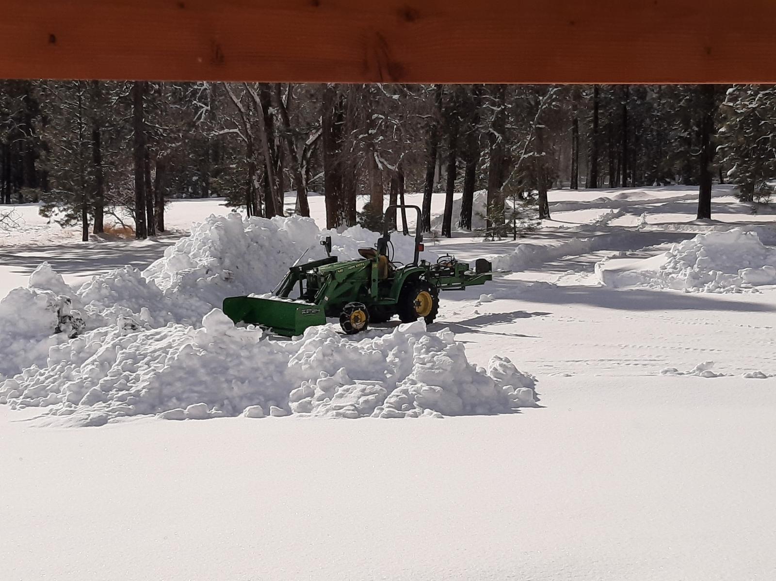
Spring has been postponed at my house for awhile. Ten inch snowfall overnight the night before last. But, it's okay as my tractor is equipped with a snow pusher. - John

-
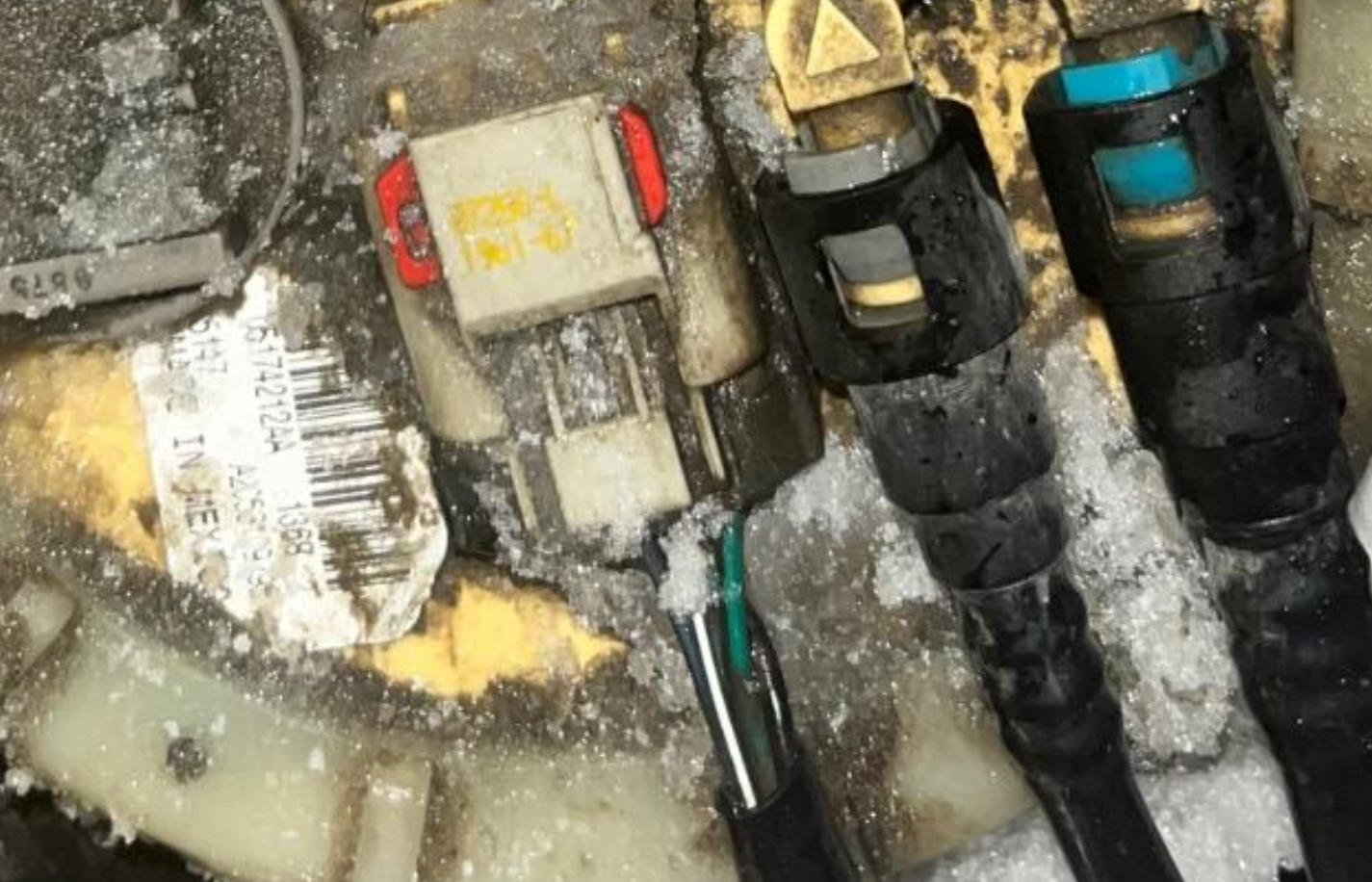
Your photo shows four wires connected to the module. This indicates there may be an in-tank pump. - John
-
Good job! - John
-
@Nomad2015, I apologize for being "harsh". That was not my intention. I will stay out of the discussion and maybe others can help you. - John
-
So, the belt came off and you turned the engine off. Why did you disconnect batteries and remove fuses? I am missing the relationship here. - John
-
I was hoping that you were going to answer my question from my previous post. You also haven't verified that you have battery voltage on the alternator output wire with a test light. Answering questions and performing tests are very important for moving forward with diagnostics. At this point, I still don't know which wire you left disconnected and if this wire is still disconnected. Ensure grid heaters are disconnected. If you have all of the alternator wires connected (the question that is still unanswered) and there is battery voltage at the alternator output terminal (verified with a test light), then start the engine. If battery voltage rises and steadies at around 14 volts, then the alternator is charging. - John
-
Need to be clear here. There are three connection points on the back of the alternator. The two small connection points are for the two small field wires. The large insulated connection point is for the alternator output wire which has an uninterrupted path to the driver side battery. Is this the wire you left disconnected? If so, the alternator cannot deliver current to the battery. In fact, if any of the three wires are left disconnected, the alternator cannot charge the batteries. Also, there may or may not be a ground wire connection on the back of the alternator. - John
-
Do not replace any parts yet! If you are in fact seeing 60 volts DC at the alternator output with everything properly connected, this means that continuity has been lost somewhere between the alternator output and the driver side battery. The 140 amp fuse is in this path along with the associated wiring. Use a test light with an incandescent bulb (not a multi-meter) and perform the following test: With engine switched off, clamp one end of the test light to a battery ground and touch the other end of the test light to the alternator output. The test light should light up brightly. If it does not, you now know where to start looking. - John
-
Don't replace anymore parts! A simple test light (with an incandescent bulb) and a wiring diagram are your friend. It is definitely possible that a previous owner added some additional wiring as @Mopar1973Manmentioned. I would start troubleshooting by connecting a test light to the fuel pump solenoid and begin disconnecting non switched OEM power sources until the light goes out. If it doesn't go out, then I would start looking for additional wiring from an non switched source. - John
-
Looking for "cause and effect" here. Did the cross-over tubes with a good seating pattern match up with the cylinders that were firing? Hopefully, the shop kept track of which injectors and cross-over tubes came out of which cylinders. - John
-
I believe it is a vent / rollover protection valve. It should be present on all fuel modules. I have one on my fuel tank module. - John
-
W-T believes that only two things need to be in a shop. You've seen one (his truck) - the other...., - John

-
Everyone diagnoses things differently. You probably just tightened the bolts and figure all is well. I try to go directly to the root of the problem. I would have set up a security camera system to find out who was trying to steal my exhaust manifold. Good job spotting that loose bolt! - John
-
The accident could have caused more damage than what was observed - not that unusual. The impact likely distorted the door frame in a manner that is creating your problem. You will have to study it some to find what is bent or twisted, then come up with a way to repair it. Sometimes you can get creative and straighten something that seems impossible to straighten. It is better to fix what is wrong rather than trying to make the door fit what is wrong. Are you doing all of the work yourself? - John
-
@Basranabread, good job using the test procedures you selected. You drew an informative conclusion. Let us know when you get the new pump installed. - John


