

- Replies 71
- Views 50.2k
- Created
- Last Reply
Top Posters In This Topic
-
Mopar1973Man 18 posts
-
SASQCH 16 posts
-
Gil2264 5 posts
-
ISX 4 posts
A better way to browse. Learn more.
A full-screen app on your home screen with push notifications, badges and more.
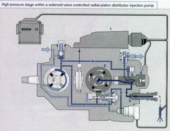


Ok Gang... You all have seen the Dodge FSM book minimum pressure of 10 PSI. Well I started to do some thinging and relized even that is too low. Here lets take a look at a pic here... http://forum.mopar1973man.com/attachment.php?attachmentid=878 So now let assume your fuel pressure average is about 12 PSI which is above the 10 PSI minimum pressure. Driving down the highway at 55-65 MPH your going to be flowing at least 2-3 GPH through the pump. But now let add a twist to it. New situation... Going up to Seven Devils Campground its a 17 mile drive up a 1 lane dirt road that is steep. I'm dragging a utility trailer with 2 ATV's. Ok for the sake of the post we'll say the fuel pressure is still 12 PSI. Climbing that grade I'm going to be flowing 7-10 GPH through that pump which is a good thing because the high flow keeps the pump lubed and cooled. But now the weekend is over time to drive home. So on the way down I set the exhaust brake and put it into 2nd gear and let it limp down the rough old trail it take about 45 minutes to 1 hour to return to the highway. So now the whole way down the mountain there is 12 PSI heading into the VP44 and but now your not throttling much if at all coming down the steep grade. So this means there is no flow to the injectors... And the Overflow valve is closed because you need 14 PSI to open it. So basically there is no fuel flow. So now the electronics and the mechanical part start to heat up the stale fuel and break it down. Remember diesel fuel is a very poor lubricant anyways. So now you see this is really easy to burn up or damage a injection pump. Now I'm starting to suggest 14-15 PSI as a minimum pressure and 20 PSI as a maximum pressure. This now keeps the overflow valve open and the fuel flowing through the pump while its spining and keeping the VP44 electronics cooled... Any thought on this???