All Activity
Yesterday
-
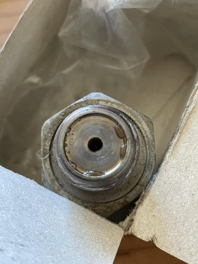
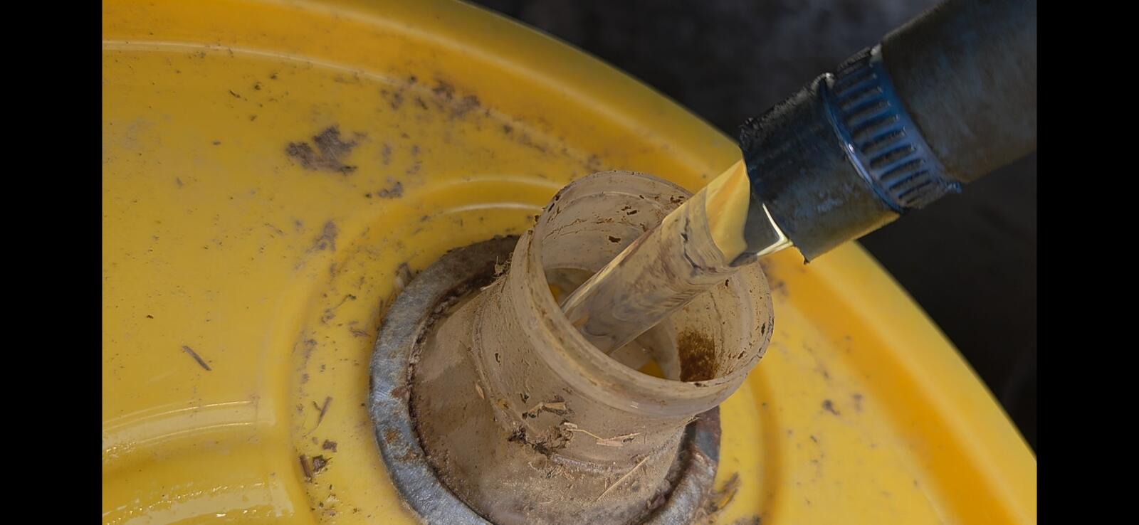
In the photo - is that water setting on the surface of the fuel rail pressure sensor? Is the lift pump an in-tank pump? Is the fuel filtration system still OEM? If it was my truck, I would be looking at removing the fuel tank and thoroughly cleaning it. Or, if you have the ability to remove the bed of the truck, that would give you good access to removing the fuel canister, which in turn will give you access to pumping out the fuel and cleaning the tank. Remove the fuel line from the fuel filter to the CP3 high pressure fuel pump and flush thoroughly. After the tank is cleaned and filled with fresh fuel (new filter installed, you could use the lift pump to purge the fuel lines up to the CP3 pump (leave the CP3 disconnected). The not-so-good news is that you will not know how much damage has been done to the high pressure fuel system (including injectors) until you perform all of the above-mentioned work. John
Last week
-
No, I didn't. Four attempts at turning over the engine with no start. Heard a weird sound in the engine compartment after the fourth, not the fuel lift pump. Then turned over/started on the fifth try. I'm worried you are on to something here. The OEM FCA didn't rattle when shaken, frozen. After the p0088 came back and the engine sounded sick idling, our next solution was to try a new fuel rail pressure sensor (Bosch again). My guy installed it, said the engine idled fine briefly and then went sick again. When he took the original out, he found there was particulate matter on the mounting surface. How to get rid of 3/4 tank or more of diesel and clean this thing out? I'm going to have to tow it somewhere. Can the fairly new FCA and pressure sensor be cleaned and recovered? I'm sick to my stomach.
Earlier
-
What else will I need to get to run a auto instead of a manual with everything. Brackets? Cables? Wiring? ETC... Computer flash most likely, as I understand it....
-
As for fuel mileage I have to ask how many miles on the injectors? How is the lift pump pressure? I've seen Thor with a new in tank pump and was going into a vacuum trying to pull fuel. Might wanna check being you are towing trailers with it. 100k miles is about all CR injectors are good for.
-
Also, I forgot to respond to the above. The bearing likely seized and resulted in a broken bracket. My brother-in-law's 2003 truck had a loose / noisy fan hub bearing, which was caught on an inspection. If gone unnoticed, the same result could have occurred. I periodically remove the serpentine belt and inspect all pulley bearings. They will fail - the inspection just stops it from being a catastrophic failure. John
-
I am just following down your post in order of events. Thanks for providing good detail, but I still have a couple of questions. Did you replace the fuel filter. Have you replaced the fuel filter since this event? Just for clarification - "turning over" means the starter is cranking the engine, but the engine is not running. Can you give more detail to your particular "no start" situation? Has the fuel filter been replaced after the "water-in-fuel" incident? I think that the 16 mpg hauling a heavy load is unrealistic. The 12-13 mpg sounds more reasonable - even with the lighter loads. Unless loads are weighed and fuel tank fill-ups and driving conditions are documented over a long period of time and trips, the reported fuel economy is very subjective and usually inaccurate. The common rail fuel system (beginning in 2003 for Dodge Cummins engines) runs at much higher fuel pressures than the '99 VP44 engine that you have become familiar with. Consequently, the common rail engine fuel system (including the high pressure pump, FCA, and injectors) cannot tolerate any foreign material in the fuel system. Introducing water means that other foreign matter (dirt) is being introduced as well. More than likely there is much more foreign matter remaining in the fuel tank from the original source of contamination. Also, since the common rail fuel systems is completely computer controlled, good electrical continuity is extremely important. Batteries in poor condition can intermittently set diagnostic trouble codes. For example, the FCA operation is controlled by the ECM and related wiring and wiring connections. Improper voltage in any part of this circuit could lead to a performance issue with the FCA. The FCA mechanical valve portion could have foreign matter lodged in it, which could result in the valve sticking. This could happened even with a new Bosch FCA if contamination is still present. In almost all diesel engine applications (even before the common rail fuel system), any time water was introduced into the fuel system, the fuel filter needed to replaced multiple times until the contamination was cleared. Sometimes the fuel tank needed to be removed and cleaned. You do need a mechanic with good diagnostic skills and knowledge of the Cummins common rail fuel system. I have been turning wrenches professionally over half of my life and am skilled in many areas, but I cannot skillfully diagnose a common rail fuel system symptom. John
-
My 2004 3500 I bought from a friend two years ago with only 77k on it is giving me grief! We use it only for hauling hay and a horse trailer periodically. Right now there's a big fire nearby and it would be ideal that it is operational to evacuate if needed, but it is not! In January the engine started making a horrible noise at it turned out the fan clutch bracket had broken and wrapped the cable around the fan! Pricey repair and I learned that it is a flaw in this generation. Then my husband topped off the tank at Costco in February not long after that repair. He noted a water in fuel light and so we drained the fuel canister and the light went away. Then the truck sat a good while before I needed it to get hay. When I started it, there was a CEL. My code reader pulled a p0088, high fuel rail pressure. I read up on that and saw it wouldn't be good to drive it even to a shop, prone to stalls and possible injector/engine damage. AI said FCA. I read water in fuel could corrode the FCA and cause this. I met a mechanic through work so he came out to suss things out, used his pro diagnostic scanner. The engine was really idling rough/erratic while he was running the diagnostics. When the engine was turned off, the fuel pressure remained high, indicating the FCA was toast. I ordered a new Bosch replacement. He came back and installed it and she purred like a kitten and the pressure went down when turned off like it was supposed to. We thought that was it. A couple of weeks went by and I started the truck with no issue, backed it up to my trailer to hook up for use the next morning. The next morning it refused to start for five attempts before finally turning over. Before the last attempt, I did hear an odd noise from the engine compartment, not the fuel life pump. But then it started, and no CEL. I hauled animals to my friend's place, stopped and started a couple of times without issue, and then started again to come home. No problem. Now it has been sitting for a few weeks and I went out today to move the truck to hook up to another trailer and low and behold the CEL is back!!! Put the reader on it and p0088, and idling roughly again! WTAF?!!! I can't believe the BOSCH part is bad. What's the next likely culprit? I of course didn't want to drive it because I don't want to get stranded or ruin anything. I re-upped my subscription here hoping someone can give me the magic bullet. I contacted my mechanic who is going to come back on Monday. I just don't have the time or determination anymore to do it myself, but seeking info because he's not a diesel mechanic per se or familiar with these trucks, but he's reasonable, physically capable (me, not so much anymore) and willing. What else should we be zeroing in on with the diagnostics? Nothing else popped after re-running the scan after installing the FCA. Last additional note of interest to me: I borrowed this truck back in 2022 before I bought it, hauled a 16 ft horse trailer to out of state to bring home a big load of livestock gates etc left behind when we moved. It got 16 mpg hauling. After I bought it, it would only get 13 mpg hauling lighter loads. I thought after replacing the FCA that it might improve but hauling that load of animals I was back down to 12-13.
-
Would you be will to share your repairs as an article too? I'll even give you a $10 credit for each article we accept. Try to balance between a good amount of words in the page as well as good phots.
-
Sure. I've been busy just fixing minor things on the 2016 Ram 2500 Cummins 4wd that I bought May 30th, 2026.
-
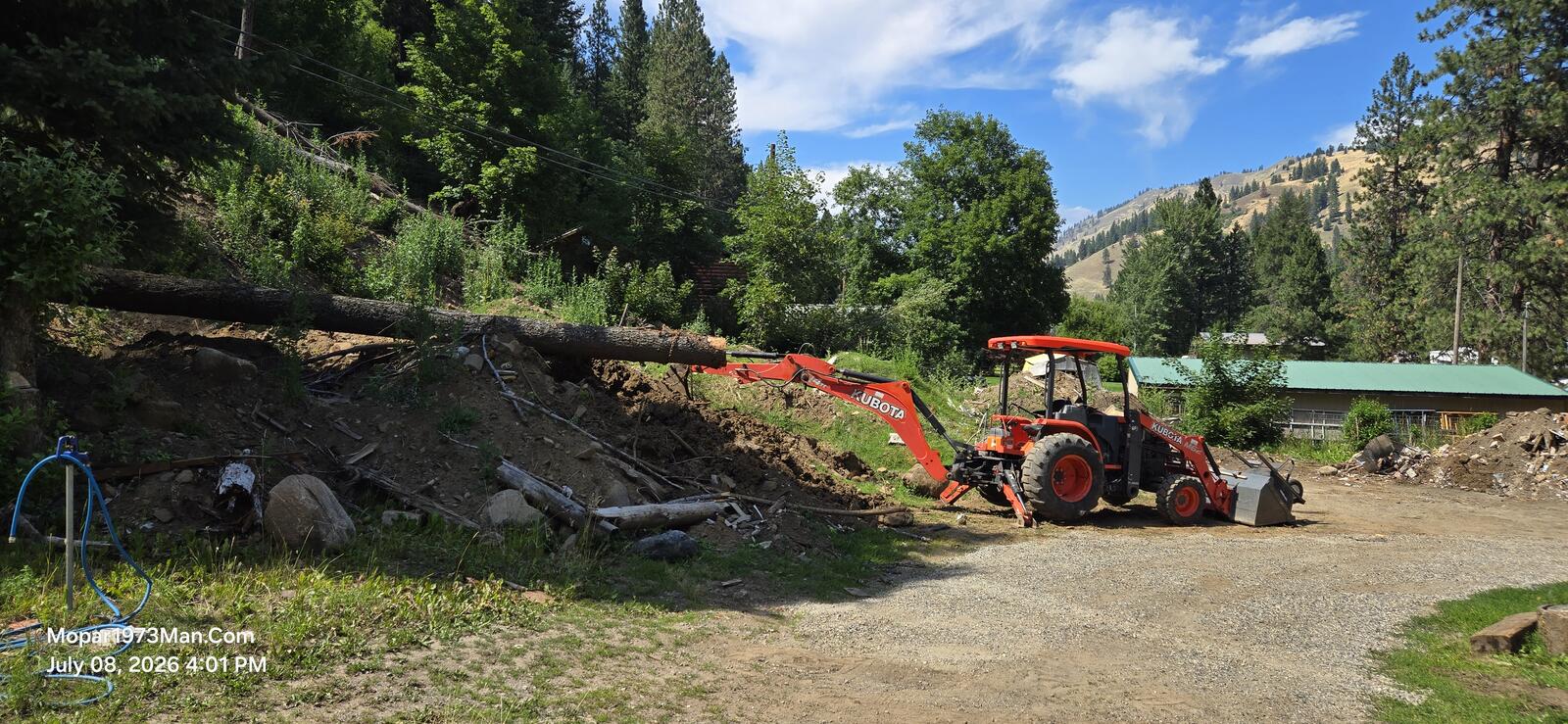
Thank you. I'm a two time cancer survivor. 2018 Christmans & 2023 Christmas. Bladder cancer ruined my bladder and then had a ileum ostomy installed. I'm unable to commerically work any longer with my ostomy bag on my belly. I'm going to keep the website going the best I can to keep it going for all you. Currently I'm busy with the clean up of the landslide and getting all that dirt moved and garbage hauled.
-
Try replacing your vp44 overflow valve. Its over looked a lot.
-
Yes, definitely have learned a lot of things I would never have thought of from him. Pretty cool dude, one of these days Id like to meet up with him at an event.
-
I follow him as well, I’ve definitely learned about some products I wasn’t aware of before, including those delivery valves.
-
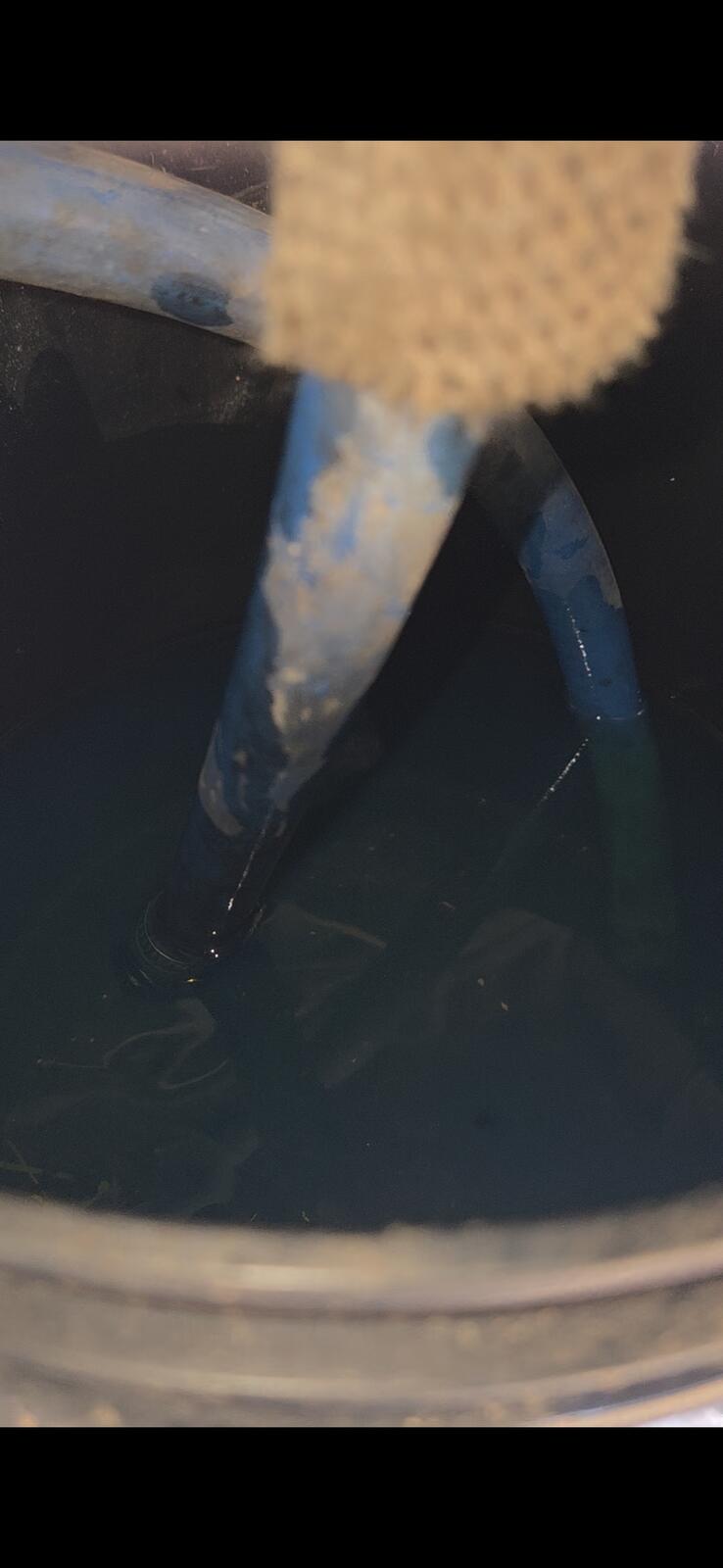
My truck has a Fleece SureFlo sending unit, FASS Titanium Signature Series 100G lift pump with Wix filters on it, 1/2in line from the sending unit to the injection pump (still using the factory filter canister), 3/8 return line from the T to the tank. If the truck has been sitting for a while (couple days), it'll start fine. The longer you drive it, the harder it is to restart after you stop. If you drive it a couple hours and stop for gas, you might need to bleed the #3 injector to get it to restart. It does not seem to have any problems once it's running, just trying to get it started again. It did the same thing (and left my partner stranded at the same gas station...) about a year ago and that's when I installed the new sending unit and return line, and rebuilt the return T while the truck was down. That seemed to fix the problem until now. I did a bucket test with the suction and lift pump return lines both in a bucket and saw no air, and repeated the test with the suction line reconnected to the tank and just the pump return running into a bucket and saw no air. So I don't think the problem is with the tank/sending unit/lift pump/suction lines. What is the next thing I should check?
-
Hey just read about the wedding congrats and i wish you both a long and joyfull time togather ,im on 43 yr. Wife has bout skin cancer and i was just told i had a form of blood cancer and getting ready to do a cross country with wife ga. To washinton.
-
I long for the day I own a shop big enough too work out of. My "shop" is non existent at the moment. Not sure your exact geographical location in the world now mike ( rigginsish)?? but I have a camp trailer and me and my gal love a good adventure and love that country, be cool to link up and hang out some time. P.S. shes a great cook also
-
Damn!! Sorry about the bad luck, was hoping it would work out good. Hopefully thats the last of it for you guys and it runs like a too now
-
Would you be willing to write an article for here in the article section?
-
Should try a trip to Seven Devils, Idaho too but you have to walk to all the lakes.
-
Like myself I've a got a dash top already sitting here in the garage but I need a place to work so to install the dash and right now the property is in a state of flux with the landslide clean up starting. My garage is so small you can't really open the truck doors enough to work.
-
Its been super handy to have for sure but the mean time till failures is about 2 to 3 hours at best. Lost the starting system was pulling fuses and ended up breaking two fuses. Found the loose starter lead. Fixed Next morning got up and had two flat tires. Spent a day getting them fixed. Next morning get up and run the tractor for some clean up of lumber and dirt. Belt breaks and overheated. Replaced belt. Next morning I get up to move 1 tree off the hill and front driveshaft falls out and drains all 15 gallons of hydraulics fluid. Total time running 10 hours and all this go wrong.


-
Nope as soon as Mark seen it I shutdown and there it sits till I can get to Lewiston to get about 15 to 17 gallons of Kubota UDT-2 fluid for the transmission and hydraulics.
-
I havent seen his stuff and I follow almost EVERYTHING 2ng gen "cutterup" obviously the man for 12V but thanks for the post, I will check his stuff out for sure
-
Hows the new tractor working out?
-
When you fold everything backup to transport mode- recheck your fluid levels - before you put back in service! Where (all) cylinders are positioned highly dictate your fluid level! Also If you haven't done it yet, it a GOOD time to cut the hydraulic filter open and check for debris, and well obviously replace your filter. Hopefully the machine didnt run for long after it happened.


1.thumb.jpg.74c1b7da4c75becf0655089ac29de0a1.jpg)