Jump to content
Posted

With the recent snow storm I was pummeled with, I had to utilize the truck today to get to work. Unfortunately, the lift pump wasn't giving me a pre start prime. Even cranked over and running, the lift pump is still not giving pressure.


I checked the fuse, it's good. I swapped the relay out with a different one. Nothing. I checked voltage at fuse and got nothing.


Any ideas? Pump dead? Some other electrical issue?

  • Replies 37
  • Views 5.3k
  • Created
  • Last Reply

Top Posters In This Topic

Most Popular Posts

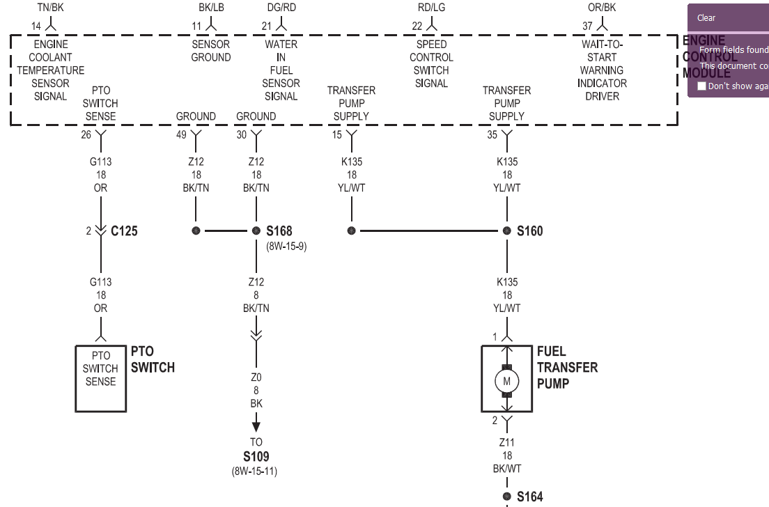
  • There should be battery voltage at both sides of the fuse and terminal #30 of the relay.   ECM voltage at terminal #86 when ignition switch is first turned on (5sec) and when starter motor is engaged

  • The schematic is fantastic reference.   NOTE - you can pull the relay from the Relay block (assuming it is plugged into a relay block)  and put a jumper wire from 87 to 30 - and see if the l

  • hex,   Chicken man is suggesting you check what is really happening at the ECM, not right at the plug where the pump plugs in.   How are you checking it?  Terminal 1 to bod
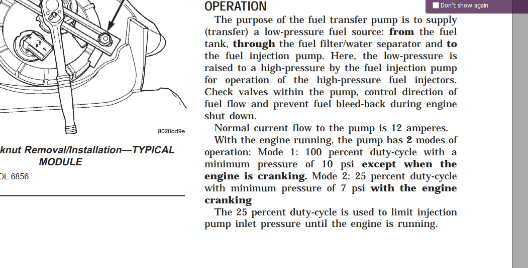
Posted Images

Featured Replies

  • Author
12 hours ago, dripley said:

Just to be clear I am speaking of testing at the pin on the ECM itself and not at the plug you connect to the relay. There maybe a problem between them.


As far as getting the prime and such back the ECM controls that. The only other way I know to control that is put a switch on it.

I wouldn't even know how to begin to do that... iirc, the ecm is not easy to get to.


I was afraid of that being the case also...

8 hours ago, CUMMINSDIESELPWR said:

time to get a fuel boss and never worry about electricity again

I wish that was the route I took from the beginning. But I also read the mechanical pumps went without their problems also.. 

hex,


Chicken man is suggesting you check what is really happening at the ECM, not right at the plug where the pump plugs in.


How are you checking it? 

  • Terminal 1 to body ground or terminal one to terminal 2?  (you should check both ways to see if there is an issue with the wire to ground or the ground.  (you could also check the resistance to terminal 2 relative to the negative battery post?
  • You also need to go directly to the ECM connector and check for 12v at 15 and 35.  do they have 2v or 12v?
  • notice the S168.....  that is a splice...  some of our splices are ugly.....   if you get 12v at 15 and/or 35 but only 2v at fuel pump terminal 1 you have a splice issue.


image.png.25211579921b2d4c3e6bce07a46a8056.png


HTH

Hag

51 minutes ago, hex0rz said:

I wouldn't even know how to begin to do that... iirc, the ecm is not easy to get to.

There is a pin out on one of the ECM on one of wiring diagrams in the articles section. That will show you the pin # for the pump. It is a pita to get to as you say. Unbolt the fuel filter canister, if you still use yours, and move it out of the way. Access is much better. Use a straight pin and stick it in where the wire goes into the connector. Then start the engine and get a voltage reading at the pin. At least you will know wherher or not its the ECM or the wiring. 


@Haggar is one of those power supply for the short prime and the 20 second or so run when bump the starter?  I would have to assume so. Why else would you need 2 power supplies to one pump? I have to admit I never noticed it before. If that is the case one those wires will only be hot briefly at key on then hot for 20 seconds or so when you bump the starter. 


If I am right @hex0rz only one of those pins will be hot while the engine is running. 

Drip,

I believe you are correct, but not certain.   I know in the manual they talk about a lowered voltage during starting, but I don't  know how they accomplished it.


Here is the description of the 25% duty cycle.  I assumed the same relay, just frequency operated, but maybe it is a totally different source, hence the 2 ECM outputs.


image.png.dc1a8b5768a3af523af4505e8d69c925.png


Hag

  • Owner

Its a square wave pulsing on and off. Its not a reduced voltage but a pulsing on and off 25% duty cycle square wave. Volt meter or DVM will not measure a square wave properly. You'll need a o-scope to see the pulses correctly. 

He should still be able to see a constant 12v on one of the pins with the engine running shouldn't he?

5 hours ago, hex0rz said:

I wouldn't even know how to begin to do that... iirc, the ecm is not easy to get to.


I was afraid of that being the case also...

I wish that was the route I took from the beginning. But I also read the mechanical pumps went without their problems also.. 

im sure they do however ive not ready anything so far about fuel boss and mine has had zero issues since install back in 2010. hope you get it sorted though.

  • Owner

I've been running AirDog 150 for 14 years now. The original pump died and was replaced with a 3rd Gen pump and failed shortly afterwards. Then now been replaced with a 4th Gen 165 GPH pump head and no problems since. 

Mike,


There are 2 pins coming out of the ECM. is one off during cranking and the other with a duty cycle and swap again when running, or is it two relays in parallel to carry the amperage?  (see pins 15 and 35 of the snip i made from the FSM)


That is dripley and my question.


Hag

Edited by Haggar

  • Owner
1 hour ago, Haggar said:

There are 2 pins coming out of the ECM. is one off during cranking and the other with a duty cycle and swap again when running, or is it two relays in parallel to carry the amperage?


Your correct. There is no relays in the ECM. The power leads are split out to handle the amperage load on the circuits. 


Steel covers are capacitors...

DSCF4639.JPG

If I understand correctly one pin is for the short prime and cranking and the other is for constant 12v while the engine is running? 

HEx,


Sorry about my, Drip and Mike's comments, we derailed a bit.  They don't affect you.  We are talking super specific things inside the ECM.  You just need to check (back probe) the pins 15 or 35 to see if you see 12v there.  If you see 12v there, but only 2v at the lift pump connector, you KNOW there is something wrong in the wire between.   Since there is a splice that is most likely the problem, so you can fix it.


That splice may be a common problem for many people that have blown the lift pump output from the ECM.  If  the original design (as Mike suggests) is so that the amps are divided between the transistors, if the splice fails, all the pump load could land on only one of the transistors!  It won't be too long before it fails then.


GL

Hag

Yes to what @Haggar says above. It would be better for the ECM to control the pump if that portion of it has not failed.