Jump to content
Posted

Hello all, just joined the page so please forgive me if I don't do this right. 


I have a 98 2500 24v auto, and ever since I've owned the truck I've been having this issue but just never attempted to do anything about it until now. I've just rebuilt my transmission to hold 550hp, am looking to add a tuner but I know I should fix this before I try to add more power. I have read the forum here about adjusting the apps and numerous other forums and cannot find anything to specifically relate to my issue. 


To start, my issue is that when I plug in my OBD scanner, my APPS sensor was reading 8.6% at idle and 71.3% at wide open throttle. So, after doing some reading, I attempted a reset. I unhooked the batteries, let the truck sit for about an hour with the key on, and then turned key off, hooked batteries up and continued with the reset process. I have done this multiple times and it seems to correct the readings on my scanner to 0% at idle and 100% at WOT for about one day, then it resets back to the 8.6% and 71.3%. I am pretty positive my OBD2 scanner is reading correctly, I plugged it into my friends truck whose is identical other than his being the 2000, and his read 0% at idle and 99% at WOT. His is also bone stock but appears to have much more power than mine.


Next, I tried adjusting the apps sensor using the method Mopar Man posted here in the forum. I am pretty positive my APPS sensor is stock. My idle voltage was .49v, and the back of my apps stated the voltage should be below .569v so I adjusted the apps to .54v at idle (note, I did not loosen the apps screws and rotate it, I used adjustment screws like what was recommended). I then adjusted the WOT voltage. It was reading 3.63v, and while I couldn't find an exact voltage anywhere, I found a YouTube video Mopar Man linked to the adjustment forum that said it should read around 3.8v, so I adjusted it to 3.8v. Also, I checked to be sure that the apps did not have any voltage spikes or drops throughout the travel, which it did not. It was a nice smooth climb from idle to WOT. Now, after the adjustment was completed, I checked my APPS reading on my scanner and it's now showing that my idle percentage is 10.2% and my WOT is 74.3%. I've tried resetting it a few times and continues to default back to the 10.2% and 74.3%. 


I'm stumped. I've done all the research I can to try to figure this out without creating another post because I know there's thousands of them out there, but I cannot find anything that relates to my issue. Do I need to just replace my apps sensor or is something else wrong? Any ideas or suggestions would be greatly appreciated.

  • Replies 47
  • Views 7.7k
  • Created
  • Last Reply

Top Posters In This Topic

Most Popular Posts

  • Tractorman
    Tractorman

    Here is another link.  This one is W-T's version.  I like his - he uses bigger words.   - John    

  • Great work!
    Great work!

    EEPROM and flash memory has a life expectancy in these ECMs @Auto Computer Specialist may be able to assist you.

  • Mopar1973Man
    Mopar1973Man

    Yup I would send the ECM off to @Auto Computer Specialist and let them fix the ECM. Then I would suggest pulling you alternator have it bench tested for AC ripple. Then if you replace the alternator m

Posted Images

Featured Replies

  • Owner
4 hours ago, Zach B said:


Sweet, I’ll go ahead and order the rebuild kit for it then and do the wiring modifications tomorrow to see if it helps any

Remember the ECM is still damaged, and the damage is done. Wiring mods will only insure your rebuilt ECM will not be damaged. You will continue to have issues.

  • Author
3 hours ago, Tractorman said:

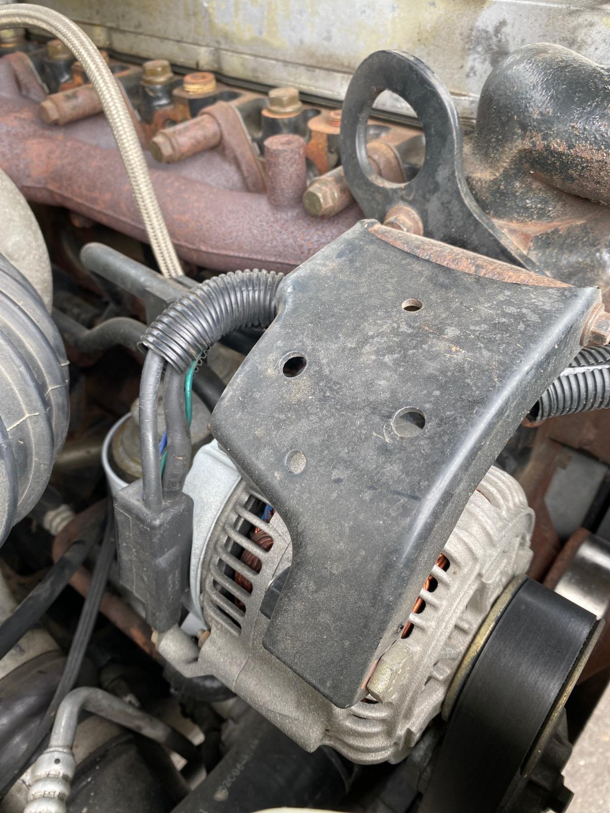
@Zach B, just FYI, note the ND emblem in the center of your first photo.  That stands for Nippondenso.


- John

Alright so that’s what it means, I tried looking online to find out what the N stood for, I figured the D stood for denso. Thanks for the info!

8 minutes ago, Mopar1973Man said:

Remember the ECM is still damaged, and the damage is done. Wiring mods will only insure your rebuilt ECM will not be damaged. You will continue to have issues.

Yep, I’m going to wait until I do the modifications and see what my AC noise  level is at before I send the computer out to get rebuilt. That way I don’t fry a new one again.


Ill let you know if I have any issues with the mods tomorrow, I do have a little question about the ground wire relocation mod but once I get it apart I may answer it myself. Thanks for all the help so far

  • Author

Alright, working on the WT ground wire mod and have a question. I was unable to find the original article so figured I’d ask here. 
 

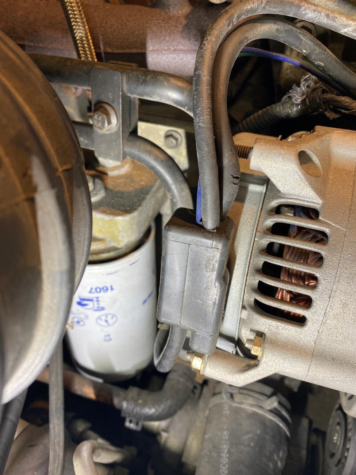
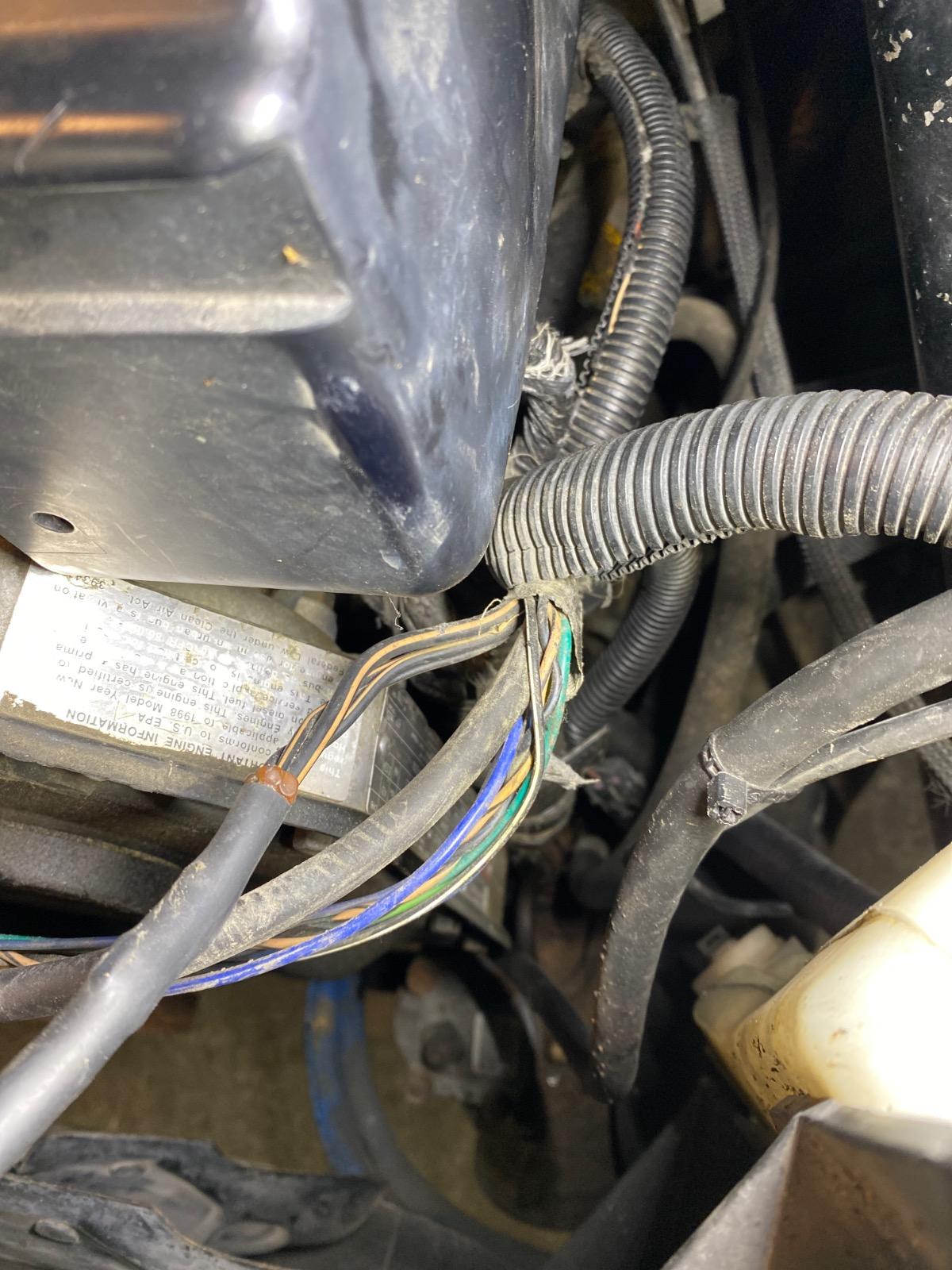
my question is in the first picture, the charge wire coming from the alternator is the large black one. I’m confused on where to cut that as the directions aren’t clear. Do I just cut it here and run it over to the passenger side battery? Or do I have to chase it all the way through the harness and unhook it somewhere?


Second question, in my second picture there is the little block that the charge wire goes into and then the wires come out the top. Do I leave that alone and run the charge wire coming out the top to the battery? In the directions it appeared the alternator did not have this little block on it with the wires coming out the top.

image.jpg

image.jpg

I think this will link you to the Mopar1973Man's version of the W-T wiring modification.


https://mopar1973man.com/cummins/articles.html/24-valve-2nd-generation_50/51_engine/electrical/w-t-ground-wire-mod-simplified-r574/?do=getLastComment&d=4&id=574


The alternator output wire is in a loom that crosses in front of the engine eventually arriving at its connection at the power distribution center.  It is a large gauge wire connected to a 140 amp fuse at the entry of the PDC.  Remove this wire from the fuse and connect the wire  to the positive terminal on the passenger side battery.  I recommended installing a 150 amp fuse in-line near the passenger side battery.  This fuse will prevent a fire should the the alternator ever have a serious short ciruit to ground.   I left my alternator output lead long until I establish a permanent mount for the in-line fuse.


- John

Edited by Tractorman

  • Author
42 minutes ago, Tractorman said:

I think this will link you to the Mopar1973Man's version of the W-T wiring modification.


https://mopar1973man.com/cummins/articles.html/24-valve-2nd-generation_50/51_engine/electrical/w-t-ground-wire-mod-simplified-r574/?do=getLastComment&d=4&id=574


The alternator output wire is in a loom that crosses in front of the engine eventually arriving at its connection at the power distribution center.  It is a large gauge wire connected to a 140 amp fuse at the entry of the PDC.  Remove this wire from the fuse and connect the wire  to the positive terminal on the passenger side battery.  I recommended installing a 150 amp fuse in-line near the passenger side battery.  This fuse will prevent a fire should the the alternator ever have a serious short ciruit to ground.   I left my alternator output lead long until I establish a permanent mount for the in-line fuse.


- John

Okay I understand now. I was a little lost In molar mans version of the mod but now I see what needs done with the power wire. Thank you for the reply

Molar man🤣😂🤣


Let me chew on that awhile.....


I love technology......NOT


I don't know if it was just psychological or not, but after doing the ground mod on my truck, it seemed to start easier/quicker and shifts felt better.

Don't forget the PCM ground mod also.

Here is another link.  This one is W-T's version.  I like his - he uses bigger words.


- John


Edited by Tractorman

Reading these comments about low voltage causing problems with the ECM creates a question. 
Did Cummins or Dodge correct these issues on later year models? 2007? Asking because my son has a 2007 and we are having electrical issues. Batteries replaced and going down overnight. 

  • Staff
3 hours ago, Max Tune said:


I don't know if it was just psychological or not, but after doing the ground mod on my truck, it seemed to start easier/quicker and shifts felt better.

Don't forget the PCM ground mod also.

Since I did mine I find woman more charged up when near my truck.

Edited by JAG1

  • Staff
1 hour ago, DeepEastTexas2Gen said:

Batteries replaced and going down overnight. 

There is most likely something staying on that you don't see.  You will have to perform a draw test to find it.  My work van had a bad radio; even thou it was shut off it was using .075 amps.  20 milliamps (0.020 amps) are what you want to see when everything is turned off and over 0.030 amps is a problem.  There must be a large drain overnight.to deplete 2 batteries.


1 hour ago, JAG1 said:

Since I did mine I find woman more charged up when near my truck.

When the women get charged up near his truck...JAG1 tens to short-circuit.

  • Author
3 hours ago, Tractorman said:

Here is another link.  This one is W-T's version.  I like his - he uses bigger words.


Cool, that’s what I was looking for. I didn’t get the chance to read through it yet and I already completed the mod, but so far everything works fine. I tested my AC noise and it’s down to .025-.033v at idle. I wasn’t sure how to test to see if I needed the parallel cables though. In mopar mans simplified article, he said to put the black probe on the battery and red probe on clean metal on the block. I just found a clean bolt head going into the block. I set the multimeter (Fluke 110plus) to the DCmv scale and it wouldn’t take a reading, it read OL on the display. Also, what does he mean by take jumper cables and run from negative post to negative post? Am I testing DCmv between the two negative terminals? Just not sure what I’m supposed to be doing or what I am doing wrong

  • Staff

Red (positive lead) to the B+ terminal of the alternator; the one with the 10MM nut on it.  The black (negative lead) goes to ground. 

Set the meter to ac voltage.

  • Author
1 minute ago, IBMobile said:

Red (positive lead) to the B+ terminal of the alternator; the one with the 10MM nut on it.  The black (negative lead) goes to ground. 

Yep, that’s what I did to test AC noise and got the reading of .025-.033v. Got the same reading from both batteries. 
 

What I’m talking about is mopar man said to test if you need the parallel cables, you are supposed to set the multimeter to DCmv and put the black probe on a battery terminal and the red probe on the block. The reading that your supposed to get is around .003mv. I was confused on this part because when I placed my multimeter probe on the battery and then the block it read OL. 

  • Owner

From the battery to the block on either side. I only measure 0.003 volts. If it not low then you need to change your ground cables not add a parallel cable. Parallel cable will only mask the issues of bad cable(s). I say fix the problem don't mask it with other added grounds.


Another way to test hook jump cables between the negative ground and the block and check the voltage drop again. In the 9 different trucks I tested I got no difference in reading adding extra ground to the block or between batteries.


Like most think I only work ony truck. Not true I've got lots of Cummins trucks I work on from ugly to super bad ***.

  • Author
12 minutes ago, Mopar1973Man said:

From the battery to the block on either side. I only measure 0.003 volts. If it not low then you need to change your ground cables not add a parallel cable. Parallel cable will only mask the issues of bad cable(s). I say fix the problem don't mask it with other added grounds.


Another way to test hook jump cables between the negative ground and the block and check the voltage drop again. In the 9 different trucks I tested I got no difference in reading adding extra ground to the block or between batteries.


Like most think I only work ony truck. Not true I've got lots of Cummins trucks I work on from ugly to super bad ***.

I got it figured out, I measured .002-.003 volts with the truck off and .004 with it running.


Even though I got the AC noise down to .025-.033v, I think I’m still going to rebuild the alternator. I’ve been looking and can’t seem to find a kit that comes with the new diode specifically for the denso on my truck. Does anyone have a link or a place to get the kit from? 
 

Now that I’ve done the WT ground mod and the PCM protection mod, After I rebuild the alternator and my AC noise is still at the levels it is now, I should be good to send my ecm out and get it repaired, right? No more risk of it getting damaged again?

  • Author
On 8/10/2022 at 12:25 AM, Mopar1973Man said:

Give @Genos Garage a shot there our vendor on the might have what your looking for.

Took a look at Genos Garage. I found the rebuild kit, but it only includes brushes and bearings. I’m looking for the rectifier/diode to replace. I can’t seem to find one for my specific alternator. I went to densos website and got the part number for the alternator my year/model truck, but when I Google search it I can’t find any of the rectifiers that fit that model.