


Everything posted by Mopar1973Man
-
Basically comes down to @Great work! ability to make the software rich enough to allow easy reprogramming of the timing and fuel tables.
-
Biggest thing that qould capture my attention to remove all ECM limitation for fuel and boost mapping. If it could be expanded to say 100 PSI of boost and create a fuel map that would cover that wide boost table.
-
Stock lift pump lead from the ECM has no relay and is power directly through the ECM. If there is issues with the lift pump circuit the ECM needs to be sent to @Auto Computer Specialist for inspection and repair. This is one reason I like the AirDog fuel system because it uses a protection relay and ECM is only used to trigger the relay. Any fuel pump that directly powers from the ECM is bad idea. When the pump has issues like locked rotor the amperage load will spike and damage the ECM. Oh little secret I'm going to release a AirDog install video soon. I just finish the video work for the draw straw. It's on my laptop and needs a bit of editing.
-
Weird... ive must of jump started hundred of rigs with my setup never popped a breaker or the PCM protection fuse 5A on the alternator blue wire.
-
Remember the adjustment on the cable is not used ot take up slack oin the shoes the starwheel should be used for that. The cable adjustment is to take the cable slack out that's all if you adjust the cable and you see the cables pull at all then you over adjusted and will have shortened pull and possibly dragging the rear brakes unnecessarily.
-
Make sure that adjuster is installed correctly if you reverse it it will unscrew completely. Don't ask me how I know.
-
There is a lot that can be done on that tune. Final ratio does have huge difference in the way power gets to the ground and how much heat is generated in engine, transmission and rear axle.
-
Economy speaking you shouldn't be over 100% till after 15 PSI at the earliest kind of like running the secondary on a carb all the time (not efficient). Timing is all wrong too and over advanced creating negative torque being that advanced. (Again not efficient) No retarding state so spooling is poor.
-
When you get the new hardware kit for the drums.better do both sides. Now that cable is a fixed length as the shoes expand out too far it will cause the adjuster arm to rotate the star wheel upward as your looking at it.
-
Sorry to say that tune is not very efficient. There is many problems with it.
-
3.73 is about the best you can get for towing and daily use economy wise. 3.55 is good but getting wee bit low for cruising RPM personally. I don't per se race so top speed doesn't matter. What does matter is being close to 2,000 RPM at 65 MPH. Just for info Thor is a true 3.73 on stock 265/75 R16 so it's about 2100 RPM at 65 MPH.
-
I just had a good conversation with @Hutch24v just a bit ago. He's looking to squeak out just a bit more MPGs out of his truck. Again he's another person with improper ratios and EGT's are higher and fuel usage as well. He's running 285's and 47RE transmission which 4th gear is 0.68 vs. my 5 speed at 0.75 so it down lower in the final ratio. I'm going to try and help out and look at both of his tunes and hopefully get him the MPG he need to survive the "Biden Energy Crisis" which is affecting all of us like here its $6.029 for diesel in New Meadows when I rolled through this morning. For optimal cruising RPM for 65 should be close to 2,000 RPM's. Like I mention to Hutch24v if your EGT's are below 600*F your doing better than 20 MPG. If your EGT's are higher than 600*F then your lower than 20 MPG. Just a rule of thumb for guessimate on MPG. Just consider at 65 MPH your consuming at least 3.25 gallons of fuel per hour for 20 MPG.
-
Thanks... I'm going to be posting little things like this of @Honey Badger and I trips out in the back country and stuff like that. Might wanna spread the word of TikTok, Instagram, Facebook because I'm going to be posting to these more and more.
-
I know this a common issues for guys adding wheels and oversized tires but to show a quick clip of running down the pavement semi-flat ground at 66 MPH and the tach shows a prefect 2,000 RPM's. The EGT floats today about 600*F, and boost is about 3-5 PSI. Had to try mounting to the side window and see if the GoPro could do it. I found out the LED lighting screws with the frame rate with the flashing displays which its not actually doing.
-
Just for info purpose here is the link to the TikTok page for the website... https://www.tiktok.com/@mopar1973man
-
All truck have either a fuse or fusible link. Would suck big time if the alternator short out and burn that charge lead and possible fire.
-
You guess it. Yup your right.
-
https://www.tiktok.com/@mopar1973man/video/7117491575768304942?_t=8Tmzg5A8pqA&_r=1 After doing the Quick Update video I mounted the camera on the windshield and cranked up the music and rolled out.
-
I've got the reset-able 150 breaker for 5 years now no issues.
-
Time to pull the drums...
-
Actually you should do the the W-T ground wire mod. The AC noise issues from the charging system is the cause of the electronics failure. No because the PSG is damaged on the VP44 so hot wiring will net you the same results too because the fuel signal is missing.
-
P0252 code... There is no fuel signal to the fuel pin in the pump so no fuel can be injected. I'm sorry to say but your going to need to replace that VP44. I would suggest giving our site vendor a call @dieselautopower and pick up a new injection pump and just replace it.
-
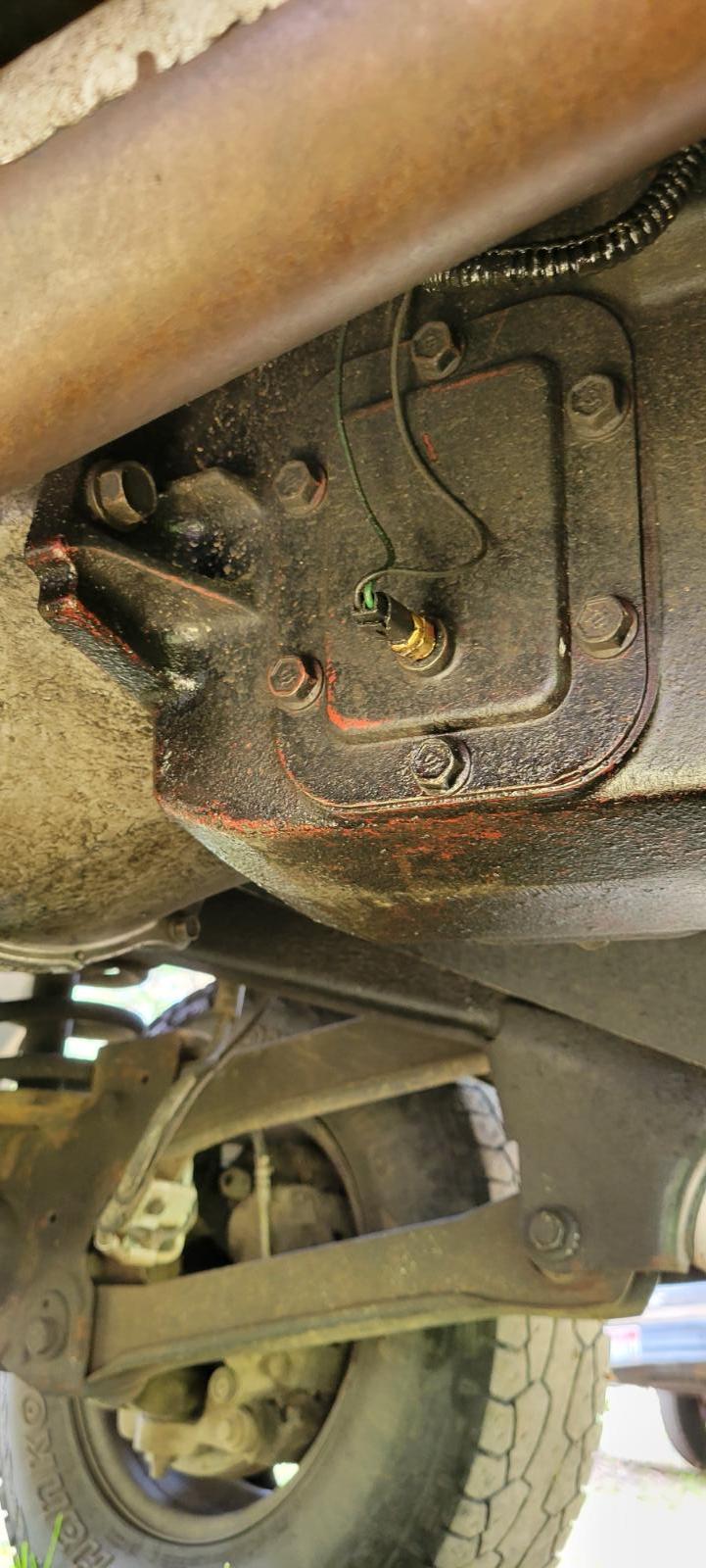
Fast Coolers really don't do much other that give a fooled read that is lower because the sensor is away from the actual gear and the fluid appears cooler. What got me thing on those was when I was measuring fluid temps using a meat thermometer and just dipped in the hole was cooler than measure near the gear teeth which was way hotter. So Fast Cooler just moves the sender away from the source of heat and showing the cooled stagnate oil in the coolers. I've got no coolers but the temperature sensor near the PTO gear and give really good accurate reading being it closest to the gears. As for my set up I've heat shielded the exhaust pipe that was worth a good 30*F reduction in temperature. Now the only time I've seen high transmission temperatures was on my trip to Bridgeport CA where the head winds caused the rise being I'm pulling 17,500 pound total weight and bucking winds it was reaching 200 to 210*F since then no issues typically between 150 to 170*F running temperatures. I didn't opt for wrapping the pipe because of the amount of salt used out here that would soak up the salt and rot the exhaust pipe out faster. Even mud will do an excellent job of rotting out a wrapped pipe being every time it get wet it will soak through the fiberglass wrap. Located next to the PTO gear. Using a ISSPro EV2 gauge been programmed for warning light of 225*F.
-
@AH64ID what's weird is i got the grid heater light but did not get the error codes for the fuel leak. The code I did get was grid heater performance error. Cleared it out and it didn't come back at all.
-
I've seen where one shoe lost a nail and spring it would be fine forward but made all kinds of racket in reverse. Just the loose hardware can do that. Worth it to investigate both rear brakes and driveline.


