


Me78569
Unpaid Member
-
Joined
-
Last visited
Everything posted by Me78569
-
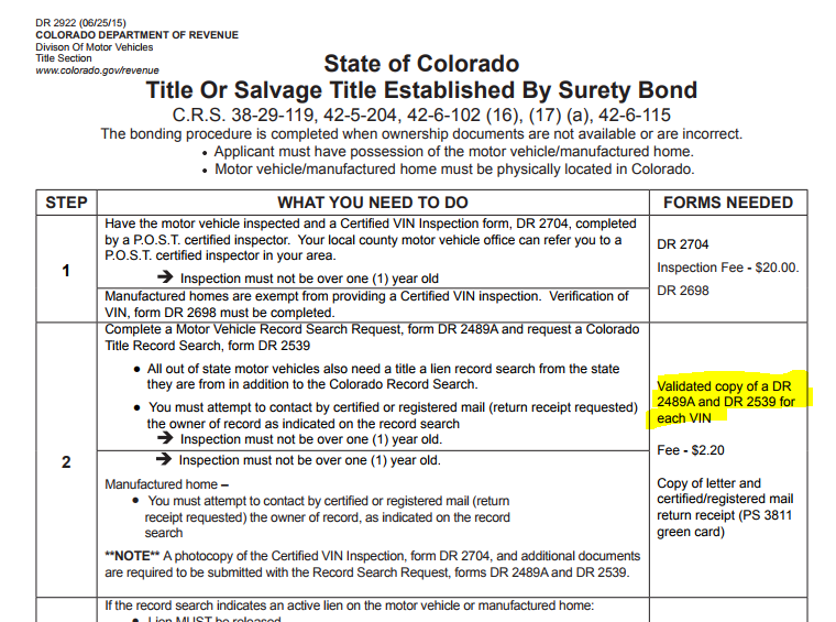
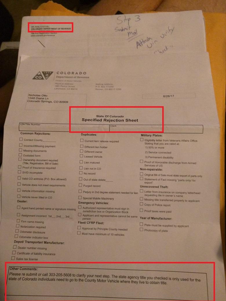
Well the story continues. I have FINALLY got step 2 done....ugh So Step 2 is as follows Great I need a DR2489A and a DR2539.... right, that's what it says?!?!? Well I got this back for the DR2539 So I called them up and asked them whats up.... they said "well you don't need 2539, I dont know why the DMV said you need it" My response was, " please look at the steps provided for this process on DR2922, step 2 says I need DR2489A and DR2539, that's why they say I need it" She says "Dont worry about it you dont need it" How I feel.. But the good news is I am almost done. I got a appraisal on the trailer, 4k, so now I just need surety bond for double the value and then I can apply for a title.... F-it I am taking it camping tonight hahahahaha

-
You def needa new lift pump. P0216 CAN be caused by low inlet pressure to the VP44, but it is not the norm.
-
32 oem 2nd gen dually lug nuts http://www.ebay.com/itm/set-of-32-1994-2002-DODGE-RAM-3500-DUALLY-LUG-NUT-NUTS-LOCKING-OEM-Wheel-/202009860467 $125
-
Try going over all the wiring to the ecm and vp44. Use dielectric grease on ALL plugs The p0216 literally means the ecm asked for xx.xx* of timing, but the VP44 could only give yy.yy* of timing. Since this happened when you hit a bump my guess would be that there was some crud in the fuel system that got dislodged when you hit the railroad tracks. This got into the timing piston and caused the issues. there is not sure fire bad vp44 only happens with x y and z. Rather you pick out common issues, if you have enough of them then the vp44 is the likely source. Do you have white smoke when you have low power? Another concerning thing is the WTS light not coming on as soon as you key on. The WTS light coming on is the ECM "booting up" . if that doesn't happen right away the ecm is on the way out.
-
DAP sells a good vp44. There are only a handfull of test stands out there to actually rebuild them so the likeliness is most pumps out there came from the same place. Get one for under $1050 that has a good warranty and beat on it HARD for a month. If it is gonna fail, as a result of a bad rebuild, it will do so in that timeframe.
-
Does that allow to tune on the fly? I think the commod is required for that?
-
if you are getting popping you should dial back the timing. I have no idea when the last time you flashed was, but some code improvements have been made to make things smoother. Flash the latest, update your app and select the 1998-2002 v2.5 profile and report back.
-
article will show you how to calibrate a HE300VE turbo using a cheap arduino board and a Canbus shield. PLEASE NOTE**** This is not a magic pill for fixing issues with the turbo actuator. If the actuator is bad then it will still need to be replaced. We get a lof of questions similar to "hey I ran this and the turbo still doesn't work" This will not fix an actuator, only calibrate a good actuator to the physical limits of the turbo vanes. Parts arduino uno $15-$30 Arduino Uno Canbus Shield $25 Plugs ~$5 Wires ~ $5 Code turboreset.ino Canbus Library CANLibrarymaster.zip This code will simple send the calibrate command to the turbo after 5 seconds of having power applied to the unit. #include <SPI.h> #include <can.h> #include <Wire.h> #define mode NORMAL // define CAN mode #define bitrate 250 // define CAN speed (bitrate) MCP CAN1 (10); //****This might be any pin 9 / 10 / 11 depending on the cnabus shield. Adjust to fit your needs unsigned int final_vane_position; void setup() { // put your setup code here, to run once: // Initialize Serial communications with computer to use serial monitor Serial.begin(115200); // Set CAN mode and speed CAN1.begin(NORMAL, bitrate); delay(5000); //wait for 5 seconds } void loop() { // put your main code here, to run repeatedly: final_vane_position = 500; byte lo_byte = lowByte(final_vane_position); byte hi_byte = highByte(final_vane_position); byte data[] = { lo_byte, hi_byte, 0x02, 0xFF, 0xFF, 0xFF, 0xFF, 0xFF }; // data message with an added counter // data[2] = 0x02 for recalibrating gearbox // Load message and send CAN1.send(0x0CFFC600, extID, 8, data); } How to Connect everything I will go into some detail here. First basics of the arduino uno and cabus_ shield. Arduino boards allow you to "stack" shields onto it via the pins on the outside edge of the board. Each Pin on the arduino and shield correlate to the Pins the code below. You can think of the Arduino as a Small computer and the Shield as a device to perform another specific task, like WIFI or Audio or in this Case Communicate on a Canbus Network. Stacking the shield onto the Arduino allows the arduino to talk in Canbus. First is the Arduino Uno Next is the Can bus Shield that you stack on top Together they should look like this. notice how they are connected, stacked on top of each other with the pins from the shield extending into the Arduino board. Each Shield will use some pins so your code must take that into consideration. Just as an example the can bus shield might use pin 10 and 11 ( I dont remember off the top of my head) so in your code you can't address those pins outside of the canbus shield use. Wire up the turbo Early Holset HE351ve's have a different wiring than late Holset HE351ve turbos Easy way to tell the difference is to look at the actuator, if it has a wiring pigtail coming out of it it is a early 351ve if the connector is built into the actuator it is a late he351 or a he300 ve, which is the same size as the he351ve. Early Holset He351ve Wiring Late He351Ve / He300ve Wiring Connectors PN's can be found over at Lilbb.com http://wiki.lilbb.com/holset_vgt#connectors He is a guru in terms of the turbo and has a GREAT off the shelf type of controller. www.lilbb.com You want to wire the Power / ground to a fused line to the battery, Don't try to power though the arduino as the turbo can pull north of 15 amps. Wire your CanHigh / Low to the Arduino shields high / low screw terminals. Upload You The Code Url's are provided in Text to step you through the process. 1. Download the Arduino program 2. Plug in your Arduino to the computer, select the right settings for the uno 3. Double click the turboreset.ino project, which will open the arduino IDE. 4. Install the canbus library. CANLibrarymaster.zip 5. Upload to the board from the Arduino program Operating The Calibrate Tool Line up the actuator arm on the turbo if the actuator was removed. Disconnect the Turbo wiring from the truck, this will set a code it's ok. Plug in your reset tool to the turbo, then connect power to the arduino board. After 5-10 seconds you should head the turbo cylce the vane position slowly. Once The turbo comes to rest it is done. Disconnect the arduino and plug the truck back into the turbo . If you continue to have issues with the turbo it is very likely that your actuator is no longer working as designed. If you found this helpful please shoot a donation my way. Everything I do is to help support the community. Thanks -Me78569 View full Cummins article
-
article will show you how to calibrate a HE300VE turbo using a cheap arduino board and a Canbus shield. PLEASE NOTE**** This is not a magic pill for fixing issues with the turbo actuator. If the actuator is bad then it will still need to be replaced. We get a lof of questions similar to "hey I ran this and the turbo still doesn't work" This will not fix an actuator, only calibrate a good actuator to the physical limits of the turbo vanes. Parts arduino uno $15-$30 Arduino Uno Canbus Shield $25 Plugs ~$5 Wires ~ $5 Code turboreset.ino Canbus Library CANLibrarymaster.zip This code will simple send the calibrate command to the turbo after 5 seconds of having power applied to the unit. #include <SPI.h> #include <can.h> #include <Wire.h> #define mode NORMAL // define CAN mode #define bitrate 250 // define CAN speed (bitrate) MCP CAN1 (10); //****This might be any pin 9 / 10 / 11 depending on the cnabus shield. Adjust to fit your needs unsigned int final_vane_position; void setup() { // put your setup code here, to run once: // Initialize Serial communications with computer to use serial monitor Serial.begin(115200); // Set CAN mode and speed CAN1.begin(NORMAL, bitrate); delay(5000); //wait for 5 seconds } void loop() { // put your main code here, to run repeatedly: final_vane_position = 500; byte lo_byte = lowByte(final_vane_position); byte hi_byte = highByte(final_vane_position); byte data[] = { lo_byte, hi_byte, 0x02, 0xFF, 0xFF, 0xFF, 0xFF, 0xFF }; // data message with an added counter // data[2] = 0x02 for recalibrating gearbox // Load message and send CAN1.send(0x0CFFC600, extID, 8, data); } How to Connect everything I will go into some detail here. First basics of the arduino uno and cabus_ shield. Arduino boards allow you to "stack" shields onto it via the pins on the outside edge of the board. Each Pin on the arduino and shield correlate to the Pins the code below. You can think of the Arduino as a Small computer and the Shield as a device to perform another specific task, like WIFI or Audio or in this Case Communicate on a Canbus Network. Stacking the shield onto the Arduino allows the arduino to talk in Canbus. First is the Arduino Uno Next is the Can bus Shield that you stack on top Together they should look like this. notice how they are connected, stacked on top of each other with the pins from the shield extending into the Arduino board. Each Shield will use some pins so your code must take that into consideration. Just as an example the can bus shield might use pin 10 and 11 ( I dont remember off the top of my head) so in your code you can't address those pins outside of the canbus shield use. Wire up the turbo Early Holset HE351ve's have a different wiring than late Holset HE351ve turbos Easy way to tell the difference is to look at the actuator, if it has a wiring pigtail coming out of it it is a early 351ve if the connector is built into the actuator it is a late he351 or a he300 ve, which is the same size as the he351ve. Early Holset He351ve Wiring Late He351Ve / He300ve Wiring Connectors PN's can be found over at Lilbb.com http://wiki.lilbb.com/holset_vgt#connectors He is a guru in terms of the turbo and has a GREAT off the shelf type of controller. www.lilbb.com You want to wire the Power / ground to a fused line to the battery, Don't try to power though the arduino as the turbo can pull north of 15 amps. Wire your CanHigh / Low to the Arduino shields high / low screw terminals. Upload You The Code Url's are provided in Text to step you through the process. 1. Download the Arduino program 2. Plug in your Arduino to the computer, select the right settings for the uno 3. Double click the turboreset.ino project, which will open the arduino IDE. 4. Install the canbus library. CANLibrarymaster.zip 5. Upload to the board from the Arduino program Operating The Calibrate Tool Line up the actuator arm on the turbo if the actuator was removed. Disconnect the Turbo wiring from the truck, this will set a code it's ok. Plug in your reset tool to the turbo, then connect power to the arduino board. After 5-10 seconds you should head the turbo cylce the vane position slowly. Once The turbo comes to rest it is done. Disconnect the arduino and plug the truck back into the turbo . If you continue to have issues with the turbo it is very likely that your actuator is no longer working as designed. If you found this helpful please shoot a donation my way. Everything I do is to help support the community. Thanks -Me78569
-
This article will show you how to calibrate a HE351VE turbo using a cheap arduino board and a Canbus shield PLEASE NOTE**** This is not a magic pill for fixing issues with the turbo actuator. If the actuator is bad then it will still need to be replaced. We get a lof of questions similar to "hey I ran this and the turbo still doesn't work" This will not fix an actuator, only calibrate a good actuator to the physical limits of the turbo vanes. Parts arduino uno $15-$30 Arduino Uno Canbus Shield $25 Plugs ~$5 Wires ~ $5 Code turboreset.ino Canbus Library CANLibrarymaster.zip This code will simple send the calibrate command to the turbo after 5 seconds of having power applied to the unit. #include <SPI.h> #include <can.h> #include <Wire.h> #define mode NORMAL // define CAN mode #define bitrate 250 // define CAN speed (bitrate) MCP CAN1 (10); //****This might be any pin 9 / 10 / 11 depending on the cnabus shield. Adjust to fit your needs unsigned int final_vane_position; void setup() { // put your setup code here, to run once: // Initialize Serial communications with computer to use serial monitor Serial.begin(115200); // Set CAN mode and speed CAN1.begin(NORMAL, bitrate); delay(5000); //wait for 5 seconds } void loop() { // put your main code here, to run repeatedly: final_vane_position = 500; byte lo_byte = lowByte(final_vane_position); byte hi_byte = highByte(final_vane_position); byte data[] = { lo_byte, hi_byte, 0x02, 0xFF, 0xFF, 0xFF, 0xFF, 0xFF }; // data message with an added counter // data[2] = 0x02 for recalibrating gearbox // Load message and send CAN1.send(0x0CFFC600, extID, 8, data); } How to Connect everything I will go into some detail here. First basics of the arduino uno and cabus_ shield. Arduino boards allow you to "stack" shields onto it via the pins on the outside edge of the board. Each Pin on the arduino and shield correlate to the Pins the code below. You can think of the Arduino as a Small computer and the Shield as a device to perform another specific task, like WIFI or Audio or in this Case Communicate on a Canbus Network. Stacking the shield onto the Arduino allows the arduino to talk in Canbus. First is the Arduino Uno Next is the Can bus Shield that you stack on top Together they should look like this. notice how they are connected, stacked on top of each other with the pins from the shield extending into the Arduino board. Each Shield will use some pins so your code must take that into consideration. Just as an example the can bus shield might use pin 10 and 11 ( I dont remember off the top of my head) so in your code you can't address those pins outside of the canbus shield use. Wire up the turbo Early Holset HE351ve's have a different wiring than late Holset HE351ve turbos Easy way to tell the difference is to look at the actuator, if it has a wiring pigtail coming out of it it is a early 351ve if the connector is built into the actuator it is a late he351 or a he300 ve, which is the same size as the he351ve. Early Holset He351ve Wiring Late He351Ve / He300ve Wiring Still looking, but hte other pins are 12v / Grnd and the inner are can high and can low. You can use a multimeter to figure out which is which. Connectors PN's can be found over at Lilbb.com http://wiki.lilbb.com/holset_vgt#connectors He is a guru in terms of the turbo and has a GREAT off the shelf type of controller. www.lilbb.com You want to wire the Power / ground to a fused line to the battery, Don't try to power though the arduino as the turbo can pull north of 15 amps. Wire your CanHigh / Low to the Arduino shields high / low screw terminals. Upload You The Code Url's are provided in Text to step you through the process. 1. Download the Arduino program 2. Plug in your Arduino to the computer, select the right settings for the uno 3. Double click the turboreset.ino project, which will open the arduino IDE. 4. Install the canbus library. CANLibrarymaster.zip 5. Upload to the board from the Arduino program Operating The Calibrate Tool Line up the turbo actuator according to this Disconnect the Turbo wiring from the truck, this will set a code it's ok. Plug in your reset tool to the turbo, then connect power to the arduino board. After 5-10 seconds you should head the turbo cylce the vane position slowly. Once The turbo comes to rest it is done. Disconnect the arduino and plug the truck back into the turbo . If you found this helpful please shoot a donation my way. Everything I do is to help support the community. Thanks -Me78569 View full Cummins article
-
This article will show you how to calibrate a HE351VE turbo using a cheap arduino board and a Canbus shield PLEASE NOTE**** This is not a magic pill for fixing issues with the turbo actuator. If the actuator is bad then it will still need to be replaced. We get a lof of questions similar to "hey I ran this and the turbo still doesn't work" This will not fix an actuator, only calibrate a good actuator to the physical limits of the turbo vanes. Parts arduino uno $15-$30 Arduino Uno Canbus Shield $25 Plugs ~$5 Wires ~ $5 Code turboreset.ino Canbus Library CANLibrarymaster.zip This code will simple send the calibrate command to the turbo after 5 seconds of having power applied to the unit. #include <SPI.h> #include <can.h> #include <Wire.h> #define mode NORMAL // define CAN mode #define bitrate 250 // define CAN speed (bitrate) MCP CAN1 (10); //****This might be any pin 9 / 10 / 11 depending on the cnabus shield. Adjust to fit your needs unsigned int final_vane_position; void setup() { // put your setup code here, to run once: // Initialize Serial communications with computer to use serial monitor Serial.begin(115200); // Set CAN mode and speed CAN1.begin(NORMAL, bitrate); delay(5000); //wait for 5 seconds } void loop() { // put your main code here, to run repeatedly: final_vane_position = 500; byte lo_byte = lowByte(final_vane_position); byte hi_byte = highByte(final_vane_position); byte data[] = { lo_byte, hi_byte, 0x02, 0xFF, 0xFF, 0xFF, 0xFF, 0xFF }; // data message with an added counter // data[2] = 0x02 for recalibrating gearbox // Load message and send CAN1.send(0x0CFFC600, extID, 8, data); } How to Connect everything I will go into some detail here. First basics of the arduino uno and cabus_ shield. Arduino boards allow you to "stack" shields onto it via the pins on the outside edge of the board. Each Pin on the arduino and shield correlate to the Pins the code below. You can think of the Arduino as a Small computer and the Shield as a device to perform another specific task, like WIFI or Audio or in this Case Communicate on a Canbus Network. Stacking the shield onto the Arduino allows the arduino to talk in Canbus. First is the Arduino Uno Next is the Can bus Shield that you stack on top Together they should look like this. notice how they are connected, stacked on top of each other with the pins from the shield extending into the Arduino board. Each Shield will use some pins so your code must take that into consideration. Just as an example the can bus shield might use pin 10 and 11 ( I dont remember off the top of my head) so in your code you can't address those pins outside of the canbus shield use. Wire up the turbo Early Holset HE351ve's have a different wiring than late Holset HE351ve turbos Easy way to tell the difference is to look at the actuator, if it has a wiring pigtail coming out of it it is a early 351ve if the connector is built into the actuator it is a late he351 or a he300 ve, which is the same size as the he351ve. Early Holset He351ve Wiring Late He351Ve / He300ve Wiring Still looking, but hte other pins are 12v / Grnd and the inner are can high and can low. You can use a multimeter to figure out which is which. Connectors PN's can be found over at Lilbb.com http://wiki.lilbb.com/holset_vgt#connectors He is a guru in terms of the turbo and has a GREAT off the shelf type of controller. www.lilbb.com You want to wire the Power / ground to a fused line to the battery, Don't try to power though the arduino as the turbo can pull north of 15 amps. Wire your CanHigh / Low to the Arduino shields high / low screw terminals. Upload You The Code Url's are provided in Text to step you through the process. 1. Download the Arduino program 2. Plug in your Arduino to the computer, select the right settings for the uno 3. Double click the turboreset.ino project, which will open the arduino IDE. 4. Install the canbus library. CANLibrarymaster.zip 5. Upload to the board from the Arduino program Operating The Calibrate Tool Line up the turbo actuator according to this Disconnect the Turbo wiring from the truck, this will set a code it's ok. Plug in your reset tool to the turbo, then connect power to the arduino board. After 5-10 seconds you should head the turbo cylce the vane position slowly. Once The turbo comes to rest it is done. Disconnect the arduino and plug the truck back into the turbo . If you found this helpful please shoot a donation my way. Everything I do is to help support the community. Thanks -Me78569
-
p0216 is almost always the vp44. Do you have good lift pump pressure? Sorry to say dead pedal plus p0216 means a vp though
-
@AH64ID Can you clarify the pricing needed to do deletes + tune yourself in realtime? I am also VERY confused on what you actually need.
-
whats the reasoning for the 2nd tank? Have you checked rockauto for lug nuts?
-
Check in the quadzilla section, it has everything you need.So jus tto be %100 clear, if you had the truck setup where you could increase TPS to %100 but not gain speed, the miss would go away as soon as you input higher TPS?I sat there for a good 5 minutes today changing power levels with that apk and it would not freeze.that thread covers it with a video walk throughthen use the profile you are using. Do you have a windows computer to update the box under the hood?@Mopar1973Man So if you were to take the truck down the road at 1000 revs in high gear then go from low TPS to high TPS would it miss until rpms come above ~1200 or would the miss clear up as soon as you put your foot into it?I can't rely on TPS input to tell the quad when to fuel since cruise control on late trucks does not report a TPS. Been down that road and we just add a bunch of issues related to that to solve this issue. I might be able to trigger it to fuel until rpms fall, but I will have to think through the issues involved with that. the hand off was different on older tunes, but they had their own issues with stalling offidle etc depending on the truck configuration. This method is MUCH smoother for manual trucks starting. Damned if I do, damned if I don't@kzimmer I can reproduce your issue, I know what it is and I can't really do anything about it. The issue is the ecm and the quad are playing ping pong with fueling. As rpms come above 950 then the quad steps in and starts to pull fuel because your tune is setup to reduce fueling due to the size of injectors. that causes the rpms to fall for a split second and the ecm then adds fuel which causes rpms to jump and the cycle repeats. @kzimmer I just looked at the smoothing function I had built and it was only in place when rpms where under 900, so removing it did nothing in this case. @mopar1973man 's issue happens regardless of tune starting point and is not limited to the 950 rpm range. His issue is an actual miss rather than rpms bouncing. still chasing that.what base flash are you using? When is the last time your updated? If you look at your data log you should see a "build date" sensor what does that say


