Tractorman
Yearly Subscription
-
Joined
-
Last visited
Everything posted by Tractorman
-
There is no doubt that recirculating the fuel inside the lift pump generates heat, but how much heat is only a guess - mainly because we don't get any real specifications for these lift pumps which leave too many variables. Then we have the fixed displacement vane pump (inside the VP44) with its own regulating valve that returns fuel back to its own inlet - so more heat generation. I am fairly sure that vane pump doesn't recirculate as much fuel as the lift pump without a dedicated return, but it does recirculate the fuel at a much higher pressure - somewhere between 100 psi to 300 psi. So, heat will be generated there as well. Again, how much? The heat generated from recirculation in both pumps could be approximately calculated IF we had information providing how much fuel was being recirculated at a given pressure in the respective pumps. The formula I used when I was in the hydraulic industry was gpm x psi / 1714 = hp. Horsepower would then be converted to watts to represent heat. Of course, these calculations were done using hydraulic oil, but there still should be some similarities. So, let's pretend there is 60 gph at 15 psi recirculating inside the lift pump. Another 20 gph is flowing out the lift pump and through the VP44 and returning to the fuel tank on this idling VP44 engine. In this example, 60 gph would be 1 gpm, hence 1 gpm x 15 psi / 1714 = .009 hp or 6.5 watts. That would be 6.5 watts of continuous heat being added to the recirculating fuel inside the lift pump. But some of that fuel would be mixing with the incoming and outgoing fuel at the rate of 20 gph, consequently carrying some of that heat away. As engine load and engine rpm increase, more fuel will be demanded by the VP44 internal vane pump and injectors, so lift pump pressure will fall, and less fuel will be recirculated inside the lift pump, which in turn will reduce heat being added to the recirculating fuel. I have no idea how accurate these calculations are, but I think it should at least give some idea as to what is going on. Feel free to punch lots of holes in this line of thinking. - John
-
I would just do the tappet cover for sure. It will make access easy for removal / installation of the tappet cover - something you don't want to fight. - John
-
@LorenS, I have a similar setup - a frame mounted FASS without a dedicated return line. Not sure of the volume because it is a used pump, but I think it is about 65 gph. I know it does heat the fuel some. I modified my VP44 fuel return line by installing a directional valve to allow fuel to return into the fuel basket during the winter months and to allow the fuel to return into the fuel tank filler neck during the summer months. I have no way to monitor fuel temperature other than to place my hand onto the lift pump body. I can definitely tell the difference when I switch the fuel return valve, though. I am fairly certain that Mopar1973Man's lift pump dedicated fuel return line and his VP44 fuel return line return fuel well away from the fuel basket, consequently he runs low fuel temperatures. - John
-
@Great work!, you make a good point here. I did mention a possible lift pump problem in my previous posts. But, what you say about a poor mechanical connection could certainly match the symptoms. Good observation on your part. - John
-
I very much agree with everything you stated. But, in this case I don't think his symptom is caused by an air leak. Here is why. He performed the free flow test into a five gallon bucket. He reported that the bucket filled to about halfway in one minute. That volume of fuel coincides with the 150 gph rated flow specification for that particular lift pump. An air leak would have certainly showed during this test because this would have been the time for air to have been drawn in because this is the only time the lift pump can flow maximum fuel through the suction line, hence the largest pressure drop. He did not report a stream of air saturated fuel. And, if the fuel would have been saturated with air, I don't think the bucket would have been as full. Once the lift pump is reconnected to the fuel system to perform as a normally operating lift pump, it will never flow 150 gph again. The maximum flow from the fuel tank to the inlet of the lift pump would be less than 50 gph on a stock or mild tune, even if the engine is placed under a demanding load. This is because even with injectors at max fuel flow and engine at max rpm, the sum of injector fuel consumption (approximately 10 gph) and the return flow from the VP44 (approximately 30 gph) via the internal vane pump would be less than 50 gph. Also, if enough air is entrained in the fuel to cause loss of engine performance under a load, the engine would likely die when the throttle is released to idle. At best, the engine would not restart without bleeding some injectors. One more thing to add - in my experience I have always seen lift pump pressure even when there is a fair amount of air in the fuel system. The lift pump will pump fuel entrained with air quite easily. It is the fuel injection pump that can't deal with the compressible solution. @Basranabreadreported a few times that fuel pressure was at "0" psi. To me, a "0" psi reading is indicative of a restriction on the inlet side of the lift pump, not entrained air. Now, of course, if it turns that his problem is air getting into the fuel system, you can just disregard everything I have posted - consider it as "buffoonery". I know I will. - John
-
I have seen that video. As I recall, the video does not replicate what is going on in the VP44 fuel system. In the video I believe the pump outlet is completely blocked forcing all fuel to flow over the regulating valve and return to the lift pump's inlet. With this condition sustained, I can understand the continuous heat generation will begin to vaporize some of the fuel and cavitation could occur at the inlet. But, this is not the real life condition that the lift pump is operating in. In the VP44 fuel system, there is always a minimum of 18 gph returning from the VP44 injection pump to the fuel tank and that minimum flow occurs at engine idle. The internal fixed displacement vane determines that volume. This means there is always a minimum of 18 gph leaving the outlet of the lift pump on an idling engine. The fuel that is recirculated within the lift pump housing (over the regulating valve and back to the inlet) is mixed with incoming fuel which will quickly stabilize heat buildup inside the lift pump. In normal designed operation the heat will not rise to the point of vaporizing fuel, so conditions for cavitation will not occur. As engine throttle is increased, more fuel will return to the fuel tank, thus more fuel will be leaving outlet of the lift pump, consequently less fuel will be recirculating inside the lift pump housing. The point that I am trying to make is that the OP has installed a new lift pump that does not use a dedicated return line. If his lift pump is cavitating, it because there is a restricted suction - whether it be in the lines, tank, or inside the lift pump - not because there isn't a dedicated return line. The link below gives a good explanation of cavitation vs. aeration. Only need to view the first couple of minutes for the explanation. https://www.google.com/search?client=firefox-b-1-d&q=airdog+caviatation+video#fpstate=ive&vld=cid:72664d2a,vid:hWeQUDyDEnY - John
-
A lift pump without a dedicated return line flows 100% of its displacement from its internal discharge location. What fuel doesn't leave the pump outlet to the VP44 gets returned to its own inlet internally. There is no cavitation. A lift pump with a dedicated return line also flows 100% of its displacement from its internal discharge location. What doesn't leave the pump outlet to the VP44 gets returned to the fuel tank. There is no cavitation. Cavitation only occurs when when the pressure on the inlet side of the lift pump falls so far below atmospheric pressure (usually greater than 15"HG vacuum) that some of the fuel will vaporize (changing from a liquid state to a vapor state) and expand before it enters the lift pump inlet. When that fuel vapor passes to the pressure side of the lift pump, the fuel vapor will suddenly collapse as it condenses to a liquid state. That sudden collapse (always in the same location) causes an implosion that is so severe that pieces of metal can be removed repeatedly at the surface of where the implosion occurs. Any pump can suffer from cavitation if there is a severe restriction on the inlet side of the pump. Neither type lift pump is truly deadheaded, even if you block the discharge port - one has an external dedicated return line, the other returns fuel to the inlet internally, but BOTH will flow the same volume fuel over the regulating valve if they are equal displacement pumps. As far as I know, Air Dog, FASS, and Carter lift pumps are all positive displacement pumps. They cannot be truly deadheaded- if they are truly deadheaded, the pump will be forced to stop rotating, or a fuse will blow, or something is going to break. And, yes, there are benefits to having a lift pump with a dedicated fuel return line, but cavitation is not one of them. - John
-
You could have a faulty lift pump or you could have a random very restrictive blockage between the fuel tank and the inlet of the lift pump. I don't think it is air getting into the suction lines. I am leaning toward the blockage. There is a fixed displacement vane pump inside the VP44. With the engine idling, that pump is returning fuel at about 18 gph to the fuel tank via the overflow valve. Under full rpm the vane pump will return fuel at about 30 gph to the fuel tank. With the engine off and the lift pump running, very little fuel is returned to the fuel tank because the fuel is being forced around the very small clearances of the vanes in the non-rotating vane pump inside the VP44. I don't think you need to drive the truck to make the symptoms happen. Try this: Bring the engine to 2500 rpm and hold it there. See if the fuel pressure begins to drop like it did on your test drive. If it does, then perform the following test: * Run a fuel line from a 5 gallon container filled with clean diesel. Connect the fuel line directly to the inlet of the lift pump. * Start the engine and let it idle to let the fuel pressure stabilize. * Bring the engine to 2500 rpm and hold it there If the fuel pressure drops slightly, but remains steady at 2500 rpm, then you know you have a suction problem. If the fuel pressure at 2500 rpm behaves like it did on your test drive, then you know you have a lift pump problem. If you can't make the symptoms happen, you may have to secure the 5 gallon fuel container in the bed of the truck and drive the truck to duplicate the symptoms. Just make sure you are being safe. When the lift pump is operating normal, what is the fuel pressure? - John
-
Definitely let us know what the outcome is. - John
-
Hmmm, seems like there are three questions here. Since I think you have been driving the truck already, you probably should tag and insure it. As far as driving the truck with the existing P0216 code, if the truck were mine, I would drive it for awhile before replacing the VP44. In fact, my truck set the P0216 code back in 2004 and the engine would de-rate at times. I drove the truck one more year (for over 20,000 miles) before I had the VP44 replaced under warranty. I learned how to get around the de-rate mode (kind of like you have learned with your truck). Since your particular problem is rather unique, driving the truck for awhile may give you time to try some other ideas to solve the problem. I can't see that it would hurt anything and time is your friend. If it turns out the pump needs to be replaced, so be it - at least you will have had the time to come up with other possible solutions. It will also give you time to find out if there are any other problems associated with the VP44 when the truck is running in the warmed up mode. It would be interesting to let the truck fully warm up and then clear the P0216 code. Immediately, start driving the truck for an hour or so and then, before the engine has a chance to cool down, recheck to see if the code P0216 has returned. - John
-
I believe you are correct. I was being a bit facetious in my previous reply. - John
-
Anything is possible I suppose. But, he did run a flow test into a 5 gallon bucket. One minute to fill the bucket half full = 2.5 gpm or 150 gph, which is what the pump is rated for. I don't think those numbers could have been attained if the pump was running backwards. - John
-
If my understanding is correct, you cannot monitor fuel pressure while driving. Is this true? If it is true, I highly recommend to temporarily plumb in a fuel pressure gauge that you can strap onto the driver side windshield wiper arm. I did this once over 18 years ago when I was told my lift pump was failing. I drove the truck back and forth to work for a week (logged over 250 miles). It turned out the lift pump was not failing at all. Since your lift pump passed the bucket test with flying colors, it is possible there is some foreign matter moving around in the fuel tank. When you start driving, that foreign matter may move into a position that temporarily blocks or partially blocks in-tank suction line. When you return home and start messing with the pump, the foreign matter may just drop away and all seems well again. - John
-
The FSM mentions one possible cause for a P0216 code is "possible wrong or incorrectly installed pump keyway." Could this be a possibility because the injection pump came from another engine? - John
-
AirDog | R1SBU371 | Raptor Pump – Universal 150 GPH does not need a return line (specifically stated in the information). Since we didn't receive a report of the results, I have to assume you didn't perform the test. Personally, I would not be driving the truck without first performing this test. - John
-
So, you saying that there is a dedicated fuel return line? To my knowledge, OEM lift pumps do not use a dedicated fuel return line. Maybe I am missing something here. - John
-
@Great work!, in his first post, @Brandon Cooperstated, "Lift pump is a Fass Titanium 220 with the 17lb spring and has a constant fuel pressure of 20PSI (gonna cut the spring and get that down a few lbs later." Maybe the VP44 (setting on a garage shelf for a year) has some internal corrosion (or growth) resulting in a sticking timing piston, or a sticking cam ring. When the engine is shut off, the timing piston moves the cam ring to the most retarded position by default (what I interpret from the Bosch VP44 manual). So, it stands to reason (as @Great work!mentioned) that the timing advance requested at startup couldn't be met, consequently 30 seconds or so later code P0216 is set and the engine is de-rated until its gets closer to operating temperature. So, maybe some extra lube could help, certainly couldn't hurt. - John
-
Does this lift pump have a dedicated return line to the fuel tank? Or, does the fuel get returned internally to its own suction? Is the lift pump OEM mounted, or frame rail mounted? Example of fuel flow with an idling engine: VP44 returns 18.5 gph to fuel tank and injectors consume .5 gph. Lift pump will be flowing 18.5 gph to VP44. I am going to round that number up to 20 gph. The 150 gph lift probably does not produce 150 gph as pressure rises, but I am going to assume that it does just for purpose of discussion. So, an idling engine would produce the following lift pump results: * 150 gph lift pump with dedicated return line - 20 gph from pump to VP44, 150 gph from tank to lift pump inlet, 130 gph returning to tank * 150 gph lift pump without dedicated return line - 20 gph from pump to VP44, 20 gph from tank to lift pump inlet, 130 gph returning to suction side of lift pump (within the lift pump housing). Two completely different behaviors. Note that with a dedicated fuel return line, you will see a maximum flow only from the fuel tank to the inlet of lift pump, consequently a large suction line is required. You are experiencing one of the drawbacks to using only a pressure gauge for troubleshooting. You need to see the flow! (Or, lack of it). And, you need to see the pressure and flow at the inlet of the VP44 (not sure where your gauge is plumbed). Your symptoms while driving strongly indicate a disruption of fuel flow. I recommend that you temporarily extend the fuel line that is connected at the VP44 and direct that fuel line into a five gallon bucket. Run the lift pump without starting the engine. You should be filling the bucket with a continuous fuel stream at the approximate rate of 150 gph. That would be 2.5 gpm. It will be obvious whether or not the lift pump is performing up to specs. As far as your condition of observing fuel pressure at 0 psi and hearing noise - it will probably mean only one the following: * cavitation - a very restrictive blockage in lines / fittings between the fuel tank and inlet of lift pump (very likely a problem) * entrained air - lots air being drawn in lines / fittings between the fuel tank and inlet of lift pump (not likely a problem - you would likely see fuel pressure, but with an erratic needle) * lift pump regulator ball chattering - usually accompanied with fuel pressure and an erratic needle. - John
-
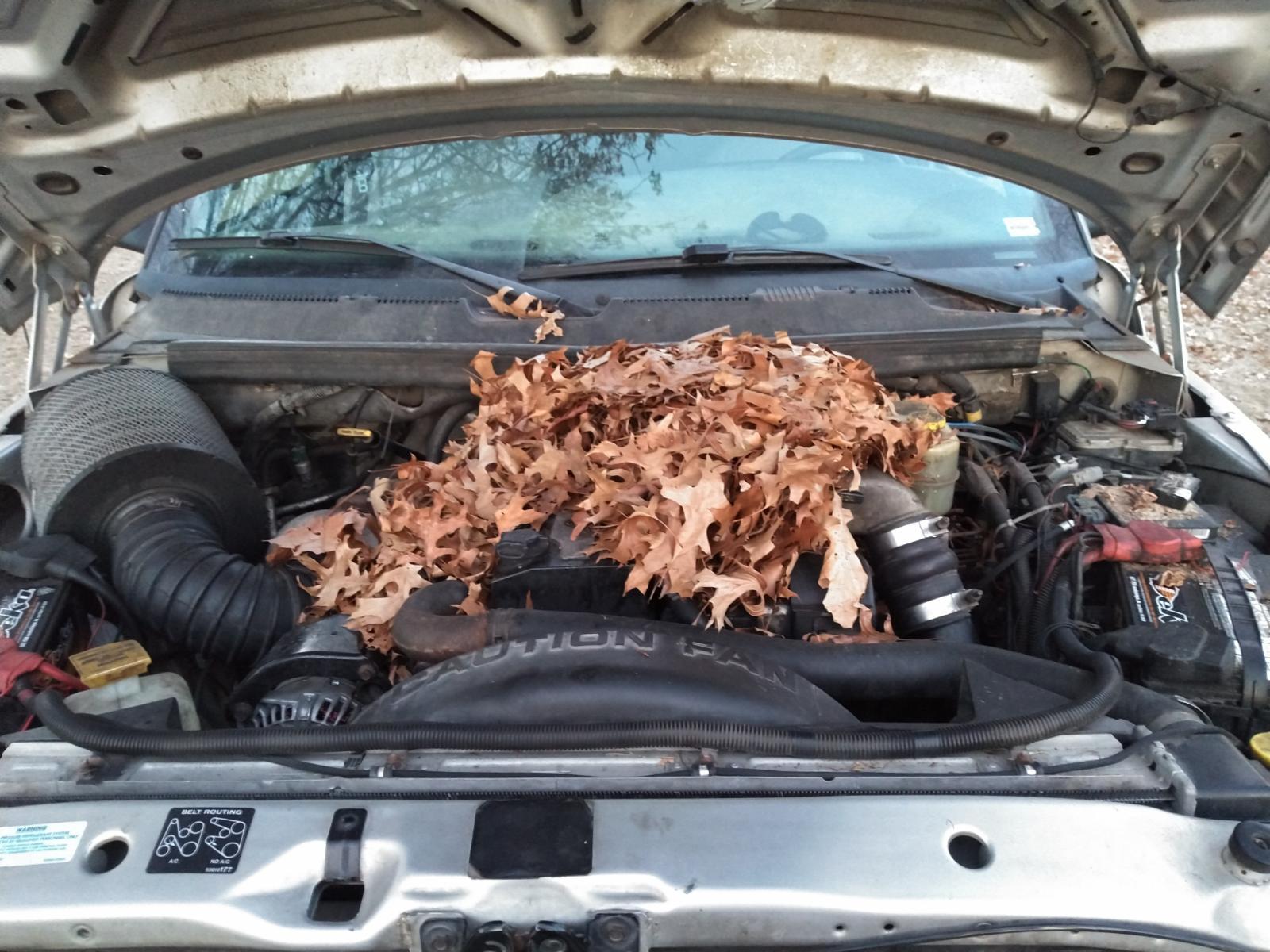
Where's the under-hood photo? I spent years making my engine quieter, which is good, except that the turbo has become quieter, too. I didn't want that to happen. - John
-
Sounds like you are on the right path. Let us know what you find. - John
-
Just shooting in the dark here, but what about using a resistor (if possible) in the coolant temperature circuit to fool the ECM into thinking the coolant is above 132° when you start the engine. Might help to confirm what you are already thinking. It is a rather odd situation that you have here. Once the ECM detects a timing issue, the ECM is de-rating the engine power. This is normal. Just odd that it happens at a very specific coolant temperature. - John
-
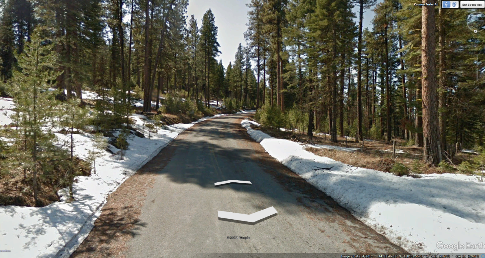
@JAG1, I think no earlier than the middle of May for camping, but definitely before the Memorial Day weekend. The lake elevation is at 5,000 feet. There will likely be leftover winter snowfields around in April, plus downed trees may still be laying across the road from winter storms. The photo is from Google Earth Street View in April, 2012. I will take a trip over in mid April to see how things look. It does appear the road is a paved road all the way to the lake - just a single lane. - John
-
Hairsprings are hard to find. I can't imagine trying to find a hairspring hole. - John
-
@JAG1, you can count me in. As I mentioned before, I will scout the area beforehand to make sure the road is clear for access to the site. - John
-
When I rake up my leaves, I don't put them under the hood like @LorenSdoes. - John