

pepsi71ocean
Yearly Subscription
-
Joined
-
Last visited
Everything posted by pepsi71ocean
-
I also have a tap on my mag pan. But i don't use it, i get my temp from the output line.
-
the pinch side of the connector is on the pigtail side, not the alternator, it just is a simple set of metal probes that go to the charging field circuit. At least on the Denso ones.
-
There is a mopar repair kit for this. The wiring on the pigtail is know to go bad, and the only solution is to cut it off backwards to good wire and splice the kit in. Not sure where to look for #'s but i know it is there.
-
That is because the blue line runs from the PCM is the 12v+ that also powers the transmission relay. The alternator is charged by varying the ground (green) as resistance to the alternator field. I discovered the issue by replacing my drivers side cable in an experiment, I told mike about it at one time when asking him about doing a vDrop test on the cables with my brother. While the ground cable did remove alot of the ac wave(on a drive test), I replaced both and still show reading on my fluke meter, however, thusfar the issue hasn't returned. (since replacing both cables)
-
I saw your post in anther thread but i figure ill ask it here. Have you verified it is indeed alternator based when it is warm? If so do a vDrop test on your battery grounds, i suspect the drivers side is borderline failing, and sending the current to the passenger battery, and causing the noise. This is exactly what happened to me with my 99. Except my issues came with heat and or humidity, if it was foggy out it was bad.
-
This is true, but if you exceed the stall speed and lock up the tc you risk destroying the TC, and or snapping shafts, just hope you have a billet input shaft, because when they let loose they usually take out the TC and the transmission pump with it.
-
have you started a thread about this? Or when you say intermittent is it based on humidity? Stock when accelerating i saw 2,100 rpms regardless of how hard i put my foot into the throttle, not sure if this helps.
-
I have a 500 lower in mine. And with my smarty, injectors and the way Ive come to drive, I'm happy. Then again, I question things now about my truck so ymmv
-
Have you verified that the alternator is charging? check that you are getting 12v+ on the alternator and at the blue on the PCM transmission circuit. I had issues with that.
-
Try unplugging the alternator and see if the issue goes away, may need to run a potential meter otherwise.
-
I too would like a long term update. I have about 46k on my dtt transmission, but I'm always going to be wondering about it. And if things i may just ship a trans out there for him to build for me.
-
The biggest thing I see, is the displacement, most semi engines are 15L motors, almost 3x the side of our trucks. when you turn the jake up, you increasing the length of time the exhaust valve is open, and creating a vacuum inside the cylinder that gives you the retarding hp you need. the new DD15's in our trucks suck, they have VGT addon's to the jake's and they don't do the same, like the older Detroit's did.
-
I replaced all of the cables on my dodge, and it also solved alot of issues with torque converter lock up. i would suggest that they may be going bad, and not to reuse them. I know that when i cut my cables that they were starting to rot out from the inside. I got my replacement from mopar on amazon.
-
Yes, I started on lvl 3 and adjusts each parameter one at a time. It was really a pia but I discovered that duration should be set to 1, an that helps allot with smoke control. It seems the TM right now is on 3 an that if I raise it to 4 it gives a little smoke on start up. Timing is set to 2. Now my testing methods were to take this truck and start it from a stop and turn the wheel and study for ease of smoke production, an the other test to was womp on it from 47-60 and observe how long it took to spool. I noticed that on lvls 3 -5 -7 -9 the amount of smoke increased so I decreased TM and duration down. When I ran my 60's I used to run the timing on 3, however with the 100's I think the truck struggles to speed up which is one of my questions. Now everyone has always said that if you max out the revo settings that it was the same as if you ran lvl 9, I have com to differ, because if so smoke production would remain the same regardless of what level you run, but as I've noticed smoke is non existent on lvl 5, (revo 3,2,1) while on lvl 7 I see a bit of a haze under the 45-60 snap test. I have discovered that lowering the tm # down really with pre boost fueling. But biggest effect is duration. By taking duration up I have noticed that effects egts as well as smoke on my 45-60 snap. At this point I have truck where basically I can step on it, get a baby haze for a second or two, but I'm concerned about the ratio of boost to torque, as the truck on different settings will product the same acceleration. I'm currently running TM 3 Timing 2 and duration 1, on lvl 7. For example, when setting on my the TM to 6 the acceleration is same, however torque is so high that under 50% throttle I see 10lbs of boost, but TM 4 I see the acceleration but 15lbs of boost. My concerns come with the notion that how do know I'm to much timing or fueling etc for motors sake. This truck now has more go power, and almost no smoke in normal acceleration. However I have discovered my transmission loves to be in 4th when it should in 3rd and in 3rd when it should be in 2nd. With this discovery helped allot the smoke, and lagging on the turbo. I will investigate this further because I do not believe this is normal. I shouldn't be cruising in 4th unlocked at 30-35 mph.
-
So I have been quite aggressive with playing with this smarty. I have tried about 35 different combinations, and several workable tunes, and I also have debunked the long standing myth that the adjustment options were related to SW. They are not. Each setting is indeed a subset, that effects the whole fuel map. With being said, I am now at a crossroads. How do I know I have hit the sweet spot. For example I have several settings where I notice the same acceleration rate is accompanied by lower boost 10'lbs or if I change tm I can see +/-15lbs on same road section. The smoke control is also there. However on other settings I feel like I am forcing the motor to accelerate, it feels like a motor that can't get out its own way. So my question is what is ideal in terms of boost, to egt. I realize that 100's are not best choice.
-
This is as normal as my truck does exactly the same.
-
Hello Everyone! Today I will be writing up the ultimate guide for all of the FASS (Fuel Air Separation System) products. I'll start with some brief history on my truck. I first put a FASS system on my truck after finding that my replacement Dodge In-tank Replacement fuel module was failing the lift pump pressure test. The Dodge In-tank pump was barely producing 8psi at idle which is below commonly acceptable standards of no less then 15psi. I contacted Walt (Wally) at FTE Diesel about the situation. I had already bought gauges from him (my first major modification), and was happy to send repeat business after he was very helpful. He told me that based on my plans for the truck the best thing to get was a FASS 95 series pump. This is the Titanium Series of the old days, which is now called the HD Series. Basic Overview of the Different FASS Systems FASS DDRP The name DDRP conjures a lot and if you have read the reports then you guessed right its called the DDRP for (Direct Dodge Replacement Pump). Unlike the Carter pumps, this one flows much better at approximately 75gph (2.5 times the Cater pump). The DDRP has had a lot of bad press, and they were considered “Junk”. And by many standards still are. However, I believe that with the correct pre-filter this pump can be made reliable. Using a GDP mounting kit can allow you to add a good pre-filter; I advise you put this filter infront of your DDRP so it can save the DDRP from eating all of the crud that will be in your tank. This will save the DDRP from known harm, often of which doomed many Carter pumps from the start. Avg cost 200-350 dollars. FASS Platinum Series The FASS Platinum Series in my opinion is northing more then the full sized pump attached to a filter base. While a step up from the DDRP it allows for filtering of fuel before it gets to your engine, unlike the DDRP which doesn’t filter at all. Do I think its worth the full price tag of about ~$500 dollars, I don’t think so, especially when you can get the HD Series or Titanium Series for a bit more. Avg cost ~$450-550. FASS Titanium Series The FASS Titanium Series is the now known version for our pickup trucks. There are two versions now; This Version runs smaller filters then the HD series however the HD series can still be used on our trucks. I have a HD series that was re-geared with 95gph gears. The Titanium Series like the HD series are reputable pumps, but unless you have an overt need to have massive fuel flow I suggest the Titanium Series will work for most if not all relevant applications. Avg cost ~$500-600 dollars. FASS HD Series The FASS HD Series was at one time the only real version of the FASS System. The 95GPH version featured shorter filters so it would fit up under the truck better then its 150GPH cousin. However with the costs of this system getting to topple 700 bucks expect reliability. Avg cost ~$625-725 Choosing a Pump System You should really choose your pump system and fuel flow based on current and future needs for the truck. You must think of where your truck is going, and if you can stand to have something break. For near stock or stock power levels a FASS DDRP is fine. But its advised to get a good pre-filter so you can filter out most of the large crud that could cause your pump to go out on you. And this is a major reason why the stock Carter lift pumps would die often taking their expensive VP-44 injection pumps with them. For those with horse power gains up to 450-500 HP a FASS 95gph pump will do fine. But you should at least upgrade to a Titanium Series pump. This will also allow you to upgrade your fuel line as well, the stock 1/4” fuel line is not enough, so FASS provides you with some 3/8’s fuel line. For those who are seeking 500HP and over expect to run a 150 GPH series pump, and ½” fuel line as well. Anything less then ½” will show especially on your fuel pressure levels as well. Why FASS? Well my first pump was a FASS, and if I got another one it would be a FASS also. I am not knocking Air Dogg, or Raptor, but the design of the system its self is what makes these pumps worth it. Regardless of your choice of mfg expect a reliable design. How the System Works (Image taken from FASS webpage HERE) The Fuel enters first from the right side, where the water is filtered out along with all particles above 144 micron. The fuel and elements (fewer than 144 Micron) are then sent through the fuel pump and then filters through the other side of the fuel filter, where you can see the clean airless fuel is drawn up and the return overflow takes air combined with the remaining fuel and sends it to the tank. The clean airless fuel is then sent to the engine. Optional Accessories Optional accessories for the FASS system are things like draw straws, fuel heater kits, and replacement Banjo bolts. Draw Straw: A draw straw is a harden tube that is used for fuel pickup from the tank. This is often used when the FASS system is replacing a truck that had been converted to the in-tank pump conversion kit. Optional diamenters are 5/8’s and ½” Fuel Heater Kit: Another option is the fuel heater kit, this allows you to run an electrical heater element to warm up your diesel fuel before it gets to the engine. This also decreases fuel viscosity and allows for better fuel psi when in colder climates. Replacement Banjo Bolts: These replace the stock Banjo Bolts on the Cummins ISB engine. The Banjo Bolts are a known restriction in the fuel supply system. Those who wish to upgrade to either 3/8”s or ½” line should note that these should also be upgraded, provided that your fuel pump kit doesn’t come with them. What Comes In A FASS Kit? My FASS 95GPH Pump came with replacement fuel line 3/8”s in diameter, (about 17 feet), replacement banjo bolts, a wiring harness with the proper fitting connectors to connect the FASS to the stock wiring harness, and a 30 am fuse on the negative side. Also included the Pump and warranty guide install instruction etic. FASS Fuel Filters Replacing your Fuel Filter is important! Depending on the model types it’s recommended to replace them ever 30,000-50,000 miles depending on configuration and use type. Those who see good clean diesel need not replace them so often. FASS Fuel Filter Cross Reference Table HD Series Manufacturer Part Number Micron Rating FASS FF-1010 10 FASS FF-1003 3 Baldwin BT-372-10 10 Carquest 85724 Unknown Cim-Tek 70032 10 Cim-Tek 70213 3 Donaldson P569381 3 Donaldson P569383 9 Fleetguard FF5588 10 Fleetguard HF6338 10 Fleetguard HF6601 10 Fleetguard HF6604 3 Luber Finer LFH4922 Unknown Luber Finer LFH8324 Unknown NAPA 1202 5 NAPA 1724 10 WIX 51116 11 WIX 51202 5 WIX 51724 10 WIX A07A03C 3 FASS Fuel Water Seperator Your fuel water separator should be replaced when you change fuel filters, but for those of you who feel they can go on forever there is a method of cleaning them. Unscrew your FASS F/W Seperator and then pour in gasoline or alcohol and then shake her up, open the drain valve and drain it out, it should clean your filter without issue. FASS Fuel Water Seperator Cross Reference Table HD Series Manufacturer Part Number Micron Rating FASS FS-1001 10 Baldwin BF1258 10 Baldwin BF1212 Unknown(est 3) Baldwin BF1214 Unknown CAT 1752949 Unknown Donaldson P551000 10 Donaldson P551001 20 Donaldson P558000 20 Fleetguard FS1000 10 Fleetguard FS1001 10 Fleetguard FS1009 14 Fleetguard FS1212 14 Luber Finer LFF1223 Unknown Luber Finer LFF8000 Unknown Motorcraft FD816 Unknown NAPA 3406 14 NAPA 3407 5 NAPA 3405 14 WIX 33407 5 WIX 33405 14 Again this is just a reference sheet ! For the FASS Titanium Series there is a word of warning. Pepsi's Notes--WARNING! In the Summer of 2010 ourfilter manufacturer relocated outside of the US and discontinued the production of the FF-2003 Fuel Filter. We made the change to an American made manufacturer which forced us to change the size of the fuel filter thread. However, the new thread size offers you a much larger selection of available cross references. If you currenty have an FF-2003 or FF-5712, those are the ONLY interchangable filters you can use with your current nipple. If you have the FWS-3003, Donaldson P553203 or the new silver fuel manifold highlighted to the left, then you have the new updated nipple. If you have the FF-2003 or FF5712 and would like to order the new filter nipple for more cross references ,simply call FASS and order Part# FSN-2001.
-
Hey guys, Pepsi here with a write up that I got from the DT forums. I have streamlined and fixed it up made it look nice etic. and added stuff where I felt it was prudent. This is a general guide and should apply to the 46RE, 47RE, and 48 RE series of transmisisons. Pepsi's Notes I am not the original author; however I have made modifications and additions as well to this article’s contents. Original is written by tactransman. The original can be viewed HERE With the legal aspect out of it here we go... ALWAYS THE FIRST STEP…. CHECK YOUR DAM FLUID! Ha, yes you guessed it most times low/high fluid levels will cause tons of issues, its best to check your fluid first. Checking your fluid can save you a ton of time and agony especially if you’re following gremlins around. So to check your fluid you must part on level ground and idle your truck in NETURAL not Park or any other gear. Check to make sure your fluid is between the two sets of dots, either the lower set or the upper set. Also take note one says “COLD” the other “HOT” this is in reference to your transmission temperature. It’s best to have a warm engine and warm fluid when measuring hot marks. Shorthanded Diagnostics… The rear clutch is applied in all forward ranges (D, 2, 1). The overrunning clutch is applied in first gear (D, 2 and 1 ranges) only. The rear band is applied in 1 and R range only. The overdrive clutch is applied only in fourth gear. However the overdrive direct clutch and overrunning clutch are applied in all ranges except fourth gear. Examples… If slippage occurs in first gear in D and 2 range but not in 1 range, the transmission overrunning clutch is faulty. Similarly, if slippage occurs in any two forward gears, the rear clutch is slipping. Applying the same method of analysis, one note that the front and rear clutches are applied simultaneously only in D range third and fourth gear. If the transmission slips in third gear, either the front clutch or the rear clutch is slipping. If the transmission slips in fourth gear but not in third gear, the overdrive clutch is slipping. By selecting another gear which does not use these clutches, the slipping unit can be determined. For another example, if the transmission also slips in Reverse, the front clutch is slipping. If the transmission does not slip in Reverse, the rear clutch is slipping. If slippage occurs during the 3-4 shift or only in fourth gear, the overdrive clutch is slipping. Similarly, if the direct clutch were to fail, the transmission would lose both reverse gear and overrun braking in 2 position (manual second gear). If the transmission will not shift to fourth gear, the control switch, overdrive solenoid or related wiring may also be the problem cause. This process of elimination can be used to identify a slipping unit and check operation. Although road test analysis will help determine the slipping unit, the actual cause of a malfunction usually cannot be determined until hydraulic and air pressure tests are performed. Practically any condition can be caused by leaking hydraulic circuits or sticking valves. Unless a malfunction is obvious, such as no drive in D range first gear, do not disassemble the transmission. Perform the hydraulic and air pressure tests to help determine the probable cause. Pepsi's Notes This portion titled Shorthanded Diagnostics came from a thread on the Cummins Forum written by the user silvertungdemon. There is a link to his post HERE. HARSH ENGAGEMENT (FROM NEUTRAL TO DRIVE OR REVERSE) Throttle Linkage Mis-adjusted. Adjust linkage - setting may be too long. Mount and Driveline Bolts Loose. Check engine mount, transmission mount, propeller shaft, rear spring to body bolts, rear control arms, crossmember and axle bolt torque. Tighten loose bolts and replace missing bolts. U-Joint Worn/Broken. Remove propeller shaft and replace U-Joint. Axle Backlash Incorrect. Check per Service Manual. Correct as needed. Hydraulic Pressure Incorrect. Check pressure. Remove, overhaul or adjust valve body as needed. Band Mis-adjusted. Adjust rear band. Axle Pinion Flange Loose. Replace nut and check pinion threads before installing new nut. Replace pinion gear if threads are damaged. Clutch, band or planetary component damaged. Remove, disassemble and repair transmission as necessary. Converter Clutch Faulty. Replace converter and flush cooler and line before installing new converter. DELAYED ENGAGEMENT (FROM NEUTRAL TO DRIVE OR REVERSE) Fluid Level Low Correct level and check for leaks Filter Clogged Change filter. Gearshift Linkage Mis-adjusted Adjust linkage and repair linkage if worn or damaged. Torque Converter Drain Back (Oil drains from torque converter into transmission sump). If vehicle moves normally after 5 seconds after shifting into gear, no repair is necessary. If longer, inspect pump bushing for wear. Replace pump house. Rear Band Mis-adjusted. Adjust band. Valve Body Filter Plugged. Replace fluid and filter. If oil pan and old fluid were full of clutch disc material and/or metal particles, overhaul will be necessary. Oil Pump Gears Worn/Damaged. Remove transmission and replace oil pump. Governor Circuit and Solenoid Valve Electrical Fault. Test with DRB3 scan tool and repair as required. Hydraulic Pressure Incorrect. Perform pressure test, remove transmission and repair as needed. Reaction Shaft Seal Rings Worn/Broken. Remove transmission, remove oil pump and replace seal rings. Rear Clutch/Input Shaft, Rear Clutch Seal Rings Damaged. Remove and disassemble transmission and repair as necessary. Regulator Valve Stuck. Clean. Cooler Plugged. Transfer case failure can plug cooler. NO DRIVE RANGE (REVERSE OK) Gearshift Linkage/Cable Loose/Misadjusted. Repair or replace linkage components. Rear Clutch Burnt. Remove and disassemble transmission and rear clutch and seals. Repair/replace worn or damaged parts as needed. Valve Body Malfunction. Remove and disassemble valve body. Replace assembly if any valves or bores are damaged. Transmission Overrunning Clutch Broken. Remove and disassemble transmission. Replace overrunning clutch. Input Shaft Seal Rings Worn/Damaged. . Remove and disassemble transmission. Replace seal rings and any other worn or damaged parts. Front Planetary Failed Broken. Remove and repair NO DRIVE OR REVERSE (VEHICLE WILL NOT MOVE) Gearshift Linkage/Cable Loose/Misadjusted. Inspect, adjust and reassemble linkage as needed. Replace worn/damaged parts. U-Joint/Axle/Transfer Case Broken. Perform preliminary inspection procedure for vehicle that will not move. Refer to procedure in diagnosis section. Filter Plugged. Remove and disassemble transmission. Repair or replace failed components as needed. Replace filter. If filter and fluid contained clutch material or metal particles, an overhaul may be necessary. Perform lube flow test. Flush oil. Replace cooler as necessary. Oil Pump Damaged. . Perform pressure test to confirm low pressure. Replace pump body assembly if necessary. Valve Body Malfunctioned. Check and inspect valve body. Replace valve body (as assembly) if any valve or bore is damaged. Clean and reassemble correctly if all parts are in good condition. Transmission Internal Component Damaged. Remove and disassemble transmission. Repair or replace failed components as needed. Park Sprag not Releasing - Check Stall Speed, Worn/Damaged/Stuck. Remove, disassemble, repair. Torque Converter Damage. Inspect and replace as required. SHIFTS DELAYED OR ERRATIC (SHIFTS ALSO HARSH AT TIMES) Fluid Filter Clogged. Replace filter. If filter and fluid contained clutch material or metal particles, an overhaul may be necessary. Perform lube flow test. Throttle Linkage Mis-adjusted. Adjust linkage as described in service section. Throttle Linkage Binding. Check cable for binding. Check for return to closed throttle at transmission. Gearshift Linkage/Cable Mis-adjusted. Adjust linkage/cable as described in service section. Clutch or Servo Failure. Remove valve body and air test clutch, and band servo operation. Disassemble and repair transmission as needed. Governor Circuit Electrical Fault. Test using DRB® scan tool and repair as required. Front Band Mis-adjusted. Adjust band. Pump Suction Passage Leak. Check for excessive foam on dipstick after normal driving. Check for loose pump bolts, defective gasket. Replace pump assembly if needed. NO REVERSE (D RANGES OK) Gearshift Linkage/Cable Mis-adjusted/Damaged. Repair or replace linkage parts as needed. Park Sprag Sticking. Replace overdrive annulus gear. Rear Band Mis-adjusted/Worn. Adjust band; replace. Valve Body Malfunction. Remove and service valve body. Replace valve body if any valves or valve bores are worn or damaged. Rear Servo Malfunction. Remove and disassemble transmission. Replace worn/damaged servo parts as necessary. Direct Clutch in Overdrive Worn. Disassemble overdrive. Replace worn or damaged parts. Front Clutch Burnt. Remove and disassemble transmission. Replace worn, damaged clutch parts as required. HAS FIRST/REVERSE ONLY (NO 1-2 OR 2-3 UPSHIFT) Governor Circuit Electrical Fault. Test using DRB® scan tool and repair as required. Valve Body Malfunction. Repair stuck 1-2 shift valve or governor plug. Front Servo/Kickdown Band Damaged/Burned. Repair/replace. MOVES IN 2ND OR 3RD GEAR, ABRUPTLY DOWNSHIFTS TO LOW Valve Body Malfunction. Remove, clean and inspect. Look for stuck 1-2 valve or governor plug. Voltage Regulator Malfunction. Depending on transmission type (Built Auto) voltage set to high causing 2nd or 3rd gear starts. See Built transmission owner’s manual, DTT transmissions run between 4.6-4.7v, stock transmission should be 5v on the Orange wire off of C2 on the PCM. NO LOW GEAR (MOVES IN 2ND OR 3RD GEAR ONLY) Governor Circuit Electrical Fault. Test with DRB3 scan tool and repair as required. (see Voltage Regulator Malfunction below) Valve Body Malfunction. Remove, clean and inspect. Look for sticking 1-2 shift valve, 2-3 shift valve, governor plug or broken springs. Front Servo Piston Cocked in Bore. Inspect servo and repair as required. Front Band Linkage Malfunction. Inspect linkage and look for bind in linkage. Voltage Regulator Malfunction. Depending on transmission type (Built Auto) voltage set to high causing 2nd or 3rd gear starts. See Built transmission owner’s manual, DTT transmissions run between 4.6-4.7v, stock transmission should be 5v on the Orange wire off of C2 on the PCM. NO KICKDOWN OR NORMAL DOWNSHIFT Throttle Linkage Mis-adjusted. Adjust linkage. Accelerator Pedal Travel Restricted. Verify floor mat is not under pedal, repair worn accelerator cable or bent brackets. Valve Body Hydraulic Pressures Too High or Too Low Due to Valve Body Malfunction or Incorrect Hydraulic Control Pressure Adjustments. Perform hydraulic pressure tests to determine cause and repair as required. Correct valve body pressure adjustments as required. Governor Circuit Electrical Fault. Test with DRB3 scan tool and repair as required. Valve Body Malfunction. Perform hydraulic pressure tests to determine cause and repair as required. Correct valve body pressure adjustments as required. TPS Malfunction. Replace sensor, check with DRB3 scan tool. PCM Malfunction. Check with DRB3 scan tool and replace if required. Valve Body Malfunction. Repair sticking 1-2, 2-3 shift valves, governor plugs, 3-4 solenoid, 3-4 shift valve, 3-4 timing valve. STUCK IN LOW GEAR (WILL NOT UPSHIFT) Throttle Linkage Mis-adjusted/Stuck. Adjust linkage and repair linkage if worn or damaged. Check for binding cable or missing return spring. Gearshift Linkage Mis-adjusted. Adjust linkage and repair linkage if worn or damaged. Governor Component Electrical Fault. Check operating pressures and test with DRB3 scan tool, repair faulty component. Front Band Out of Adjustment. Adjust Band. Clutch or Servo Malfunction. Air pressure check operation of clutches and bands. Repair faulty component. CREEPS IN NEUTRAL Gearshift Linkage Mis-adjusted. Adjust linkage. Rear Clutch Dragging/Warped. Disassemble and repair. Valve Body Malfunction. Perform hydraulic pressure test to determine cause and repair as required. BUZZING NOISE Shift Cable Mis-assembled. Route cable away from engine and bell housing. Valve Body Mis-assembled. Remove, disassemble, inspect valve body. Reassemble correctly if necessary. Replace assembly if valves or springs are damaged. Check for loose bolts or screws. Pump Passages Leaking. Check pump for porous casting, scores on mating surfaces and excess rotor clearance. Repair as required. Loose pump bolts. Cooling System Cooler Plugged Flow check cooler circuit. Repair as needed. Overrunning Clutch Damaged. Replace clutch. SLIPS IN REVERSE ONLY Gearshift Linkage Mis-adjusted. Adjust linkage. Rear Band Mis-adjusted. Adjust band. Rear Band Worn. Replace as required. Overdrive Direct Clutch Worn. Disassemble overdrive. Repair as needed. Hydraulic Pressure Too Low. Perform hydraulic pressure tests to determine cause. Rear Servo Leaking. Air pressure check clutch-servo operation and repair as required. Band Linkage Binding. Inspect and repair as required. SLIPS IN FORWARD DRIVE RANGES Fluid Foaming. Check for high oil level, bad pump gasket or seals, dirt between pump halves and loose pump bolts. Replace pump if necessary. Throttle Linkage Mis-adjusted. Adjust linkage. Gearshift Linkage Mis-adjusted. Adjust linkage. Rear Clutch Worn. Inspect and replace as needed. Low Hydraulic Pressure Due to Worn Pump, Incorrect Control Pressure Adjustments, Valve Body Warpage or Malfunction, Sticking, Leaking Seal Rings, Clutch Seals Leaking, Servo Leaks, Clogged Filter or Cooler Lines. Perform hydraulic and air pressure tests to determine cause. Rear Clutch Malfunction, Leaking Seals or Worn Plates. Air pressure check clutch-servo operation and repair as required. Overrunning Clutch Worn, Not Holding (Slips in 1 Only). Replace Clutch. SLIPS IN LOW GEAR "D" ONLY, BUT NOT IN MANUAL 1 POSITION Overrunning Clutch Faulty. Replace overrunning clutch. GROWLING, GRATING OR SCRAPING NOISES Drive Plate Broken. Replace. Torque Converter Bolts Hitting Dust Shield. Dust shield bent. Replace or repair. Planetary Gear Set Broken/Seized. Check for debris in oil pan and repair as required. Overrunning Clutch Worn/Broken. Inspect and check for debris in oil pan. Repair as required. Oil Pump Components Scored/Binding. Remove, inspect and repair as required. Output Shaft Bearing or Bushing Damaged. Remove, inspect and repair as required. Clutch Operation Faulty. Perform air pressure check and repair as required. Front and Rear Bands Mis-adjusted. Adjust bands. DRAGS OR LOCKS UP Clutch Dragging/Failed. Air pressure check clutch operation and repair as required. Front or Rear Band Mis-adjusted. Adjust bands. Case Leaks Internally. Check for leakage between passages in case. Servo Band or Linkage Malfunction. Air pressure check servo operation and repair as required. Overrunning Clutch Worn. Remove and inspect clutch. Repair as required. Planetary Gears Broken. Remove, inspect and repair as required (look for debris in oil pan). Converter Clutch Dragging. Check for plugged cooler. Perform flow check. Inspect pump for excessive side clearance. Replace pump as required. NO 4-3 DOWNSHIFT Circuit Wiring and/or Connectors Shorted. Test wiring and connectors with test lamp and volt/ohmmeter. Repair wiring as necessary. Replace connectors and/or harnesses as required. PCM Malfunction. Check PCM operation with DRB3 scan tool. Replace PCM only if faulty. TPS Malfunction. Check TPS with DRB3 scan tool at PCM. Lockup Solenoid Not Venting. Remove valve body and replace solenoid assembly if plugged or shorted. Overdrive Solenoid Not Venting. Remove valve body and replace solenoid if plugged or shorted. Valve Body Valve Sticking. Repair stuck 3-4 shift valve or lockup timing valve. Kick Down Band Out Of Adjustment Check for excessive play. NO 4-3 DOWNSHIFT WHEN CONTROL SWITCH IS TURNED OFF Control Switch Open/Shorted. Test and replace switch if faulty. Overdrive Solenoid Connector Shorted. Test solenoids and replace if seized or shorted. PCM Malfunction. Test with DRB3 scan tool. Replace PCM if faulty. Valve Body Stuck Valves. Repair stuck 3-4, lockup or lockup timing valve. CLUNK NOISE FROM DRIVELINE ON CLOSED THROTTLE 4-3 DOWNSHIFT Throttle Cable Mis-adjusted. Adjust cable. Overdrive Clutch Select Spacer Wrong Spacer. Replace overdrive piston thrust plate spacer. 3-4 UPSHIFT OCCURS IMMEDIATELY AFTER 2-3 SHIFT Overdrive Solenoid Connector or Wiring Shorted. Test connector and wiring for loose connections, shorts or ground and repair as needed. TPS Malfunction. Test TPS and replace as necessary. Check with DRB3 scan tool. PCM Malfunction. Test PCM with DRB3 scan tool and replace controller if faulty. Overdrive Solenoid Malfunction. Replace solenoid. Valve Body Malfunction. Remove, disassemble, clean and inspect valve body components. Make sure all valves and plugs slide freely in bores. Polish valves with crocus cloth if needed. WHINE/NOISE RELATED TO ENGINE SPEED Shift Cable Incorrect Routing. Check shift cable for correct routing. Should not touch engine or bell housing. NO 3-4 UPSHIFT O/D Switch In OFF Position. Turn control switch to ON position. Overdrive Circuit Fuse Blown. Replace fuse. Determine why fuse failed and repair as necessary (i.e., shorts or grounds in circuit). O/D Switch Wire Shorted/Open Cut. Check wires/connections with 12V test lamp and voltmeter. Repair damaged or loose wire/connection as necessary. Distance or Coolant Sensor Malfunction. Check with DRB® scan tool and repair or replace as necessary. TPS Malfunction. Check with DRB® scan tool and replace if necessary. Neutral Sense to PCM Wire Shorted/Cut. Test switch/sensor as described in service section and replace if necessary. Engine no start. PCM Malfunction. Check with DRB® scan tool and replace if necessary. Overdrive Solenoid Shorted/Open. Replace solenoid if shorted or open and repair loose or damaged wires (DRB® scan tool). Solenoid Feed Orifice in Valve Body Blocked. Remove, disassemble, and clean valve body thoroughly. Check feed orifice. Overdrive Clutch Failed. Disassemble overdrive and repair as needed. Hydraulic Pressure Low. Pressure test transmission to determine cause. Valve Body Valve Stuck. Repair stuck 3-4 shift valve, 3-4 timing valve. O/D Piston Incorrect Spacer. Remove unit, check end play and install correct spacer. Overdrive Piston Seal Failure. Replace both seals. O/D Check Valve/Orifice Failed. Check for free movement and secure assembly (in piston retainer). Check ball bleed orifice. SLIPS IN OVERDRIVE FOURTH GEAR Overdrive Clutch Pack Worn. Remove overdrive unit and rebuild clutch pack. Overdrive Piston Retainer Bleed Orifice Blown Out. Disassemble transmission, remove retainer and replace orifice. Overdrive Piston or Seal Malfunction. Remove overdrive unit. Replace seals if worn. Replace piston if damaged. If piston retainer is damaged, remove and disassemble the transmission. 3-4 Shift Valve, Timing Valve or Accumulator Malfunction. Remove and overhaul valve body. Replace accumulator seals. Make sure all valves operate freely in bores and do not bind or stick. Make sure valve body screws are correctly tightened and separator plates are properly positioned. Overdrive Unit Thrust Bearing Failure. Disassemble overdrive unit and replace thrust bearing (NO. 1 thrust bearing is between overdrive piston and clutch hub; NO. 2 thrust bearing is between the planetary gear and the direct clutch spring plate; NO. 3 thrust bearing is between overrunning clutch hub and output shaft). O/D Check Valve/Bleed Orifice Failure. Check for function/secure orifice insert in O/D piston retainer. DELAYED 3-4 UPSHIFT (SLOW TO ENGAGE) Throttle Valve Cable Mis-adjusted. Adjust throttle valve cable. Overdrive Clutch Pack Worn/Burnt. Remove unit and rebuild clutch pack. TPS Faulty. Test with DRB3 scan tool and replace as necessary. Overdrive Clutch Bleed Orifice Plugged. Disassemble transmission and replace orifice. Overdrive Solenoid or Wiring Shorted/Open. Test solenoid and check wiring for loose/corroded connections or shorts/grounds. Replace solenoid if faulty and repair wiring if necessary. Overdrive Excess Clearance. Remove unit. Measure end play and select proper spacer. O/D Check Valve Missing or Stuck. Check for presence of check valve. Repair or replace as required. TORQUE CONVERTER LOCKS UP IN SECOND AND/OR THIRD GEAR Lockup Solenoid, Relay or Wiring Shorted/Open. Test solenoid, relay and wiring for continuity, shorts or grounds. Replace solenoid and relay if faulty. Repair wiring and connectors as necessary. HARSH 1-2, 2-3, 3-4 OR 3-2 SHIFTS Lockup Solenoid Malfunction. Remove valve body and replace solenoid assembly. NO START IN PARK OR NEUTRAL Gearshift Linkage/Cable Mis-adjusted. Adjust linkage/cable. Neutral Sense Wire Open/Cut. Check continuity with test lamp. Repair as required. Park/Neutral Switch, or Transmission Range Sensor Faulty. Refer to service section for test and replacement procedure. Park/Neutral Switch, or Transmission Range Sensor Connection Faulty. Connectors spread open. Repair. Valve Body Manual Lever Assembly Bent/Worn/Broken. Inspect lever assembly and replace if damaged. NO REVERSE (OR SLIPS IN REVERSE) Direct Clutch Pack (front clutch) Worn. Disassemble unit and rebuild clutch pack. Rear Band Mis-adjusted. Adjust band. Front Clutch Malfunctioned/Burned. Air-pressure test clutch operation. Remove and rebuild if necessary. Overdrive Thrust Bearing Failure. Disassemble gear train and replace bearings. Direct Clutch Spring Collapsed/Broken. Remove and disassemble unit. Check clutch position and replace spring. OIL LEAKS Fluid Lines and Fittings Loose/Leaks/Damaged. Tighten fittings. If leaks persist, replace fittings and lines if necessary. Fill Tube (where tube enters case) Leaks/Damaged. Replace tube seal. Inspect tube for cracks in fill tube. Pressure Port Plug Loose Loose/Damaged. Tighten to correct torque. Replace plug or reseal if leak persists. Pan Gasket Leaks. Tighten pan screws (150 in. lbs.). If leaks persist, replace gasket. Valve Body Manual Lever Shaft Seal Leaks/Worn. Replace shaft seal. Rear Bearing Access Plate Leaks. Replace gasket. Tighten screws. Gasket Damaged or Bolts are Loose. Replace bolts or gasket or tighten both. Adapter/Extension Gasket Damaged Leaks/Damaged. Replace gasket. Park/Neutral Switch, or Transmission Range Sensor Leaks/Damaged. Replace switch and gasket. Converter Housing Area Leaks. Check for leaks at seal caused by worn seal or burr on converter hub (cutting seal), worn bushing, missing oil return, oil in front pump housing or hole plugged. Check for leaks past O-ring seal on pump or past pump-to-case bolts; pump housing porous, oil coming out vent due to overfill or leak past front band shaft access plug. Pump Seal Leaks/Worn/Damaged. Replace seal. Torque Converter Weld Leak/Cracked Hub. Replace converter. Case Porosity Leaks. Replace case. NOISY OPERATION IN FOURTH GEAR ONLY Overdrive Clutch Discs, Plates or Snap Rings Damaged. Remove unit and rebuild clutch pack. Overdrive Piston or Planetary Thrust Bearing Damaged. Remove and disassemble unit. Replace either thrust bearing if damaged. Output Shaft Bearings Scored/Damaged. Remove and disassemble unit. Replace either bearing if damaged. Planetary Gears Worn/Chipped. Remove and overhaul overdrive unit. Overdrive Unit Overrunning Clutch Rollers Worn/Scored. Remove and overhaul overdrive unit. I hope this will help future generations of Dodge Cummins owners out, I didn't copy these to take claim, I took them and put them tougher so others will be able to use this information which is now easily accessible and legible. If the original owners feel that this is a violation feel free to PM me and I will be happy to remove this if the owner feels such is prudent.
-
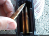
Injector Install Video Ok Guys, After a long waiting period here is my Injector install videos. All three videos are sequential and should help clear up any questions remaining from Mike's article. HERE. Pepsi's Notes While I used Mike's Injector Install write up, I felt that after installing and removing injectors several times I should shoot a movie that will help eliminate any of the "questions" that would pop up. I did this to help others out. This Guide is good for all model year Cummins ISB 5.9L Engines. The Bosch VP-44 Powered ISB to be exact. The Install video is on a 1999 Dodge RAM 3500, but the ISB engine is the same, the only difference is that the Dodge RAM version has a Valve Cover that says Dodge Cummins on it. I used Diesel Auto Power (DAP) 60 HP Injectors. They are Genuine BOSCH injectors that were bored out larger by an extra 60HP. At the time, I was shooting this movie I was diagnosing hard starts when cold conditions, even though once bled it started fine. TOOLS NEEDED Adjustable Wrench Crows Feet Metric Set 3/8" Ratchet 6" and 12" extensions (3/8"s and 1/4") Metric Socket Set 10mm-21mm 1/4 Metric Socket Set (8mm) Suggested Stuff Trash bag Shop Light Gloves Air gun nozzle, to blow air down and take the dust off the motor. Large Flat bladed screwdriver. Pepsi's Notes Around 8.40 you will see blue connectors holding the High-pressure lines together in two groups when reinstalling them its best to loosen those line blocks up so that they will fit snug when you go the put it back on, and this will also prevent the fittings from crushing them selves, causing leaks. Around 13 Mins you can see all of the engine parts I took off, that are spread around to keep things organized Pepsi's Notes If you are going to perform a routine cleaning make sure that you do each injector one at a time and replace the injectors back into the same cylinder they came out of. Once you crush the copper wires you can usually reuse them, but understand to not cross the injectors or the copper washers, this way they will reseal correctly. As shown in the video if your injector will not rise use a flat headed screwdriver to lift it up, don't force it. When reinstalling the lock down bar does not tighten to spec, instead tighten your lockdown bolt till less then snug and use the crossover tube to rotate the injector ever so slightly. Torque Settings Injector bolts (Opposed Clamp bolt) 89-inch lbs High pressure lines 28 ft lbs. (Slightly more than hand tight) If you're unsure use a torque wrench. When torquing these down, if you are to loose the fuel will leak out of the head, to tight and you will have an internal leak, which will be harder to diagnose. Most bolts you should tighten down hand tight plus 1/4 turn, or more than snug to prevent them from working loose.
- 1 comment
- 3 reviews
-
-

- 2
-
-
I third the smarty, my truck pulls hard when I was towing...
-
I have though of this as well. But I haven't really though of replacing it either.
-
After fighting Napa bull carp I dropped the money for a new denso alternator from dodge. The part number is 5104762AA and the tc issues are gone. However, my passenger side is reading .05-.06vac and the drivers side is .02-.03vac. I'm going to have to further this with Mike. The other chase right now is the vdrop testing of my ground cables. The passenger was .07vdc but the drivers side was .184vdc
-
So after extensive testing the pcm is not putting out 12v positive to the alternator/trans relay circut. Without going to the dealer to confirm yet, which will happen. Anyways after much searching I have not found anything consistent, but a whole bunch of rebuilder websites. I don't have much faith in any of them, but have any of you taken the plunge and bought a remain pcm? If so how is it holding up? I started calling junk yards around here with no luck, so I'm already assuming that either I'll have to try the internet or go to the dealer. Anyone have any help? Thanks!
-
Well the pcm is not sending the 12v signal to the alternator or the transmission relay, so it is dead as Mike thinks. Mg question is where to find a new one as from what I have heard is that all rebuilds are crap.
-
If you have no luck swap to fass, and reassemble and move on. Air dogs rep is in the dumpster and odds are the new pump they send you will also be problematic.
