Great work!
Unpaid Member
-
Joined
-
Last visited
Everything posted by Great work!
-
I'm working on a home made ECM for my truck to go along with my VP44 project. I almost found an ECM today on a burned up truck but the wiring was burned all the way to the ECM so i figured it was toast. The guy wouldn't sell it, I would have to buy the motor and he said the VP44 was bad with hot start issues. He had a V10 (blown) dually that he was going to put the cummins in. He wanted me to buy both. If he had a manual tranny in the deal I would have took it. But I skipped it. The usual diagram that many of us use has some errors in the pin names and functions. From all my VP research I know many of the details of these pin functions and thought I would share them. Pin 33 Knock sensor is wrong. Instead it is a strange bi-directional signal. its pulled down internally in the VP pin 5. When left alone it is a current mirror of the injection solenoid current, looks like its chopped or ADC sampled. When pulled up to 12 volts by the ECM it shuts off the vp. Some kind of safety function and it can monitor the solenoid current blip. It's called MAB (German). The injection 'Knock' does happen shortly after the blip. I believe the injection line delay and combustion delay is sent to the pump in a CAN message for fine tuning the timing calculation. However there is no Knock sensor. Pin 45 is output by the ECM to PCM it turns on ALT, AC, TRANS. It is a 5volt square wave at 2X the RPM. 33 Hz at1000 RPM, 16,6 Hz. It is not sysnced but free runs, but on my VP project it is synced to the crank sensor. Pin 18 is the engine position reference signal. DZG(German) it is the timing ref for the VP so it can calculate its cam donut position relative to the engine crank position. It is a 12V square wave. The trailing edge of the signal always occurs every time a piston is at 10 degrees after top dead center. It is decoded from the CKP and or CMP sensors. Pin 34 is an idle valid signal from the ECM to VP. It is 12V at idle and 0V when pressed. it is pulled up to 12V in the VP on pin 4. The APPS has 2 idle outputs that are open collector that are always in opposite states. VP pin 2 is 12v =idle, 0V = pressed. APPS pin 6 is inverted. The ECM monitors the idle signals and pot and if its happy. the ECM pin 34 changes state it is sensed at VP pin 4 LGS (German) the VP then changes a byte in the CAN message going to the ECM as a cross check then The ECM increases the fuel command byte. If the pump is Hot wired, grounding pin 4 makes the engine run at a higher RPM. CAN message from VP : 22 40 8 04 00 85 23 xx yy 79 13. The Byte in red is: 0C HEX = not running 04 HEX = idle valid state (as detected via ECM pin 34 to VP pin 4) 00 HEX = above idle operation "" yy HEX is the pump RPM MSB xx HEX is the pump RPM LSB 79 13 is the fuel temp in Kelvin encoded ?
-
The rear speed sensor goes to the ABS box on pin 1 and on pin 8. Connect a DVM to the pins and set to ohms function it should read less than 600 ohms but thats just a guess. Set the meter to beep when the leads are touched together. Hopefully the sensor resistance is low enough to cause the beep to sound continuosly. Go under the truck and wiggle the wires at the rear end on the connector and all the way up into the main harness on the frame also try tapping on the sensor with something. If the beeper is interrupted at any time then there is a bad connection or broken internal wire from years of flexing. A new pigtale is probally available that is made of special flexible wire. Next move forward to the two connectors by the body mount and behind the drivers plastic inner fender and wiggle them and just open them up and spray cleaner in them. Test 2 connect the meter to pin 1and the other lead to a good ground. leave it set in the beep mode. It should NOT beep Wiggle wires and harness along frame all the way to the ABS box if the meter beeps then a wire has been rubbed thru and is shorting to ground. The ABS box converts the bipolar sensor signal to unipolar signal that is output at pin 12 (VSS) that goes to the PCM. It then converts it to a CCD bus meeage that goes to the cluster. A momentary hic-up in the bus causes the speed to quickly go out but the gauges can linger for a few seconds. I'm not a fan of the cummins dry fit shaft seals that are supposed to perfectly wear to fit the crank.
-
I repaired one a few years back and almost made the same mistake. I had to really stare at that part to figure it out.
-
The PCM could check if the transmission sensor and the speed sensor in the rear axle are both pulsing and flag it if not. Obviously the PCM doesn't do that. When my sensor failed a few years ago I was stuck with only first gear. By removing the transmission relay in the PDC it goes into limp mode which just defaults to 3rd gear. Much better to drive home in 3rd instead of 1 st. When I was a kid I was playing around in snow and my rear wheels went from 100 mph to zero instantly on dry pavement. That shredded the nylon gear on the governor in the old GM th350 so I was stuck in 1st.
-
Sounds like it was an easy fix .
-
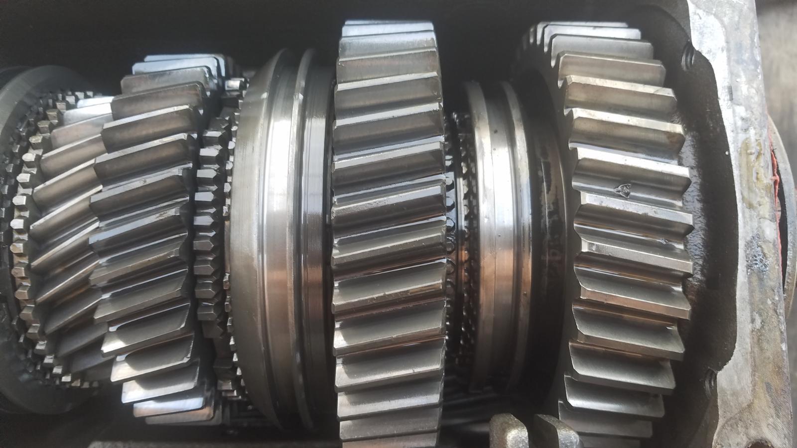
If i remember correctly the main shaft barely fits through the opening and it helps to have the input gear out and one of the front gears goes on once the main shaft is partly installed, very tricky. Then there's a roll pin that you should get started into the reverse shift fork before placing it back in the case and tapped into place in the shift rail later with a long punch. Also very tricky.
-
I thick you could put a couple pieces of angle iron behind the hub and then support it over a bucket or barrel. Then a few hits with a big soft hammer on the shaft end could do it. I pick up bed frames on trash days they make great angle iron but they are harder to drill.
-
Almost looks like something went through the gears.
-
So I found out there are different versions of the aftermarket shafts. I didn't get the one with the thrust washer groove that is supposed to fix it with the assumption that the nut will loosen. The downside of that shaft is the machined groove can weaken the shaft and the gear rocking will eventually fail. But this seems to be the preferred shaft. The torque king shaft seems the best designed one. Maybe @Mopar1973Man is on to something. The thicker lube might help cushion / dampen the diesel engine harmonics.
-
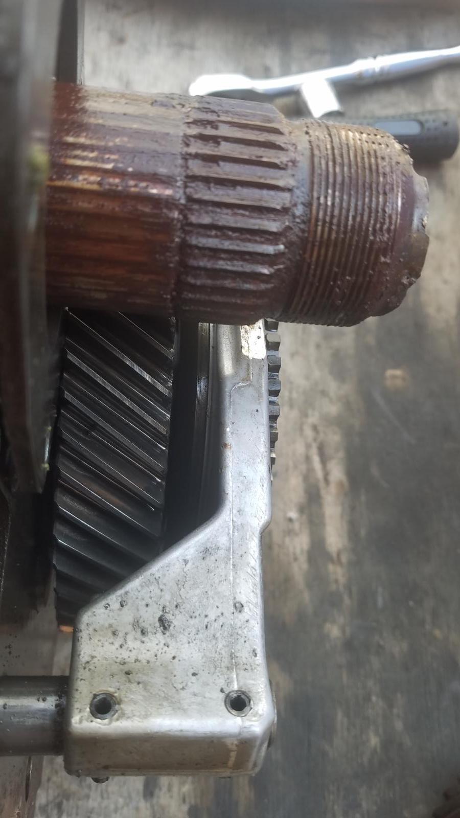
Well my friends truck with NV4500 has a problem with 5th gear nuts we have fixed it a few times now over a couple years now. 1st repair put a fancy new nut with set screws and 3 small welds about 1/4 inch wide. Mig welded nut to shaft. Lasted maybe a year 2nd repair he put the nut back on and mig welded the hell out of it, all the way around the shaft. A couple months later on a long trip with trailer the shaft broke completely where the weld was. 3rd repair we put an after market shaft in it with full splines and threads. A very expensive shaft. It had a new washer and nut with it we also replaced the 5th gear. The nut had 3 set screws with little hardened teeth. We put the thread lock on the nut and set screws and torqued with a long cheater pipe. We were advised NOT to weld anything. I also made a custom spacer on my lathe to go between the nut and transfer case bearing as plan b so if it looses up again at least the gear would still stay on the splines. Well it failed again on a long trip hauling a medium trailer. No 5th gear the nut loosened and the shaft actually walked forward in the tranny so my spacer didn't help. The shaft moved far enough that reverse has a hard time staying engaged. Should I weld it. It really needs a keyed shaft with a washer that has an internal tooth on it. Similar to the ones in the rear axle hubs. Here's the old shaft that broke. That orange stuff is from the gear oscillating on the splines. That movement causes the nut to loosen. The fancy new shaft was supposed to be a forever fix. Any opinions or advice? I'm getting tired of fighting it.
-
For code p1492 you need the spring loaded temp sensor that snaps into the original dodge battery tray. Or just find the two wires in the harness and connect a 10K ohm 1/2 watt resistor to the wires and tape into the harness that should fool the pcm and look like ~ 70 F.
-
My simple scanner does that too. When there is a companion module fault the scanner needs to be told what to expect so I have to manually select chrysler then it works ok. I suspect it's because the ISO9141 Protocol which is k-line and L-Line bidirectional comm. The protocol supports multiple ECUs/PCMs on a shared comm bus. The k-line was popular on many European cars at that time. OBDII and computers on cars were not well standardized at that time and many manufacturers winged it. So there is a lot of unsupported features.
-
I've done hard towing up bumpy mountain dirt roads before and spent most of the time in 2nd gear. I don't think the tranny was designed for it. It puts a lot on the band and hub. Plus the direct clutch is un locked but the plates sliding past each other so lots of lube is required. The engineers probably didn't envision continuous 2nd gear use.
-
You put a p pump on it right? Assuming a manual tranny. You can put an external voltage regulator on it lots of info and videos on the web. That will give you stable battery voltage. That would be a good start. Check connectors there are some behind the fender skirt that go to the back of the truck on drivers side. Just open ALL connectors and spray clean then re-seat .
-
Nice.
-
Some kits have an improved PRND valve with a hole drilled through it lengthwise. The original shuts off converter cooling flow in park. The valve body has to be disassembled and physically brushed and wiped clean. Soaking in solvent is not enough. The grit in there is tiny enough to make it through the filter.
-
Check fuse 9 10amp in the side of dash. The lt green/ black wire goes to ECM pin 5. It comes on with the key. Do you have mice in the truck?
-
Saw that on a friends truck. Same exact place.
-
Mine is bent too.
-
Even here in the states that ATF is expensive.
-
I'm assuming OD works once it upshifts. That's a good sign electrically. Check the control cable and return spring maybe sticking. Next time it happens shift to neutral for a couple seconds and then back to drive. That usually makes it shift. If so that's probably sticky valve spools in the valve body.
-
I used to charge the batteries in my boat through the 7 pin RV connector. It overheated the power pin though. So I added a seperate connector.
-
No. The CAD works even the 4x4 light works right.
-
Well I figured on retiring my old grand Cherokee because it burns so much oil and the rear bushings are shot. So that left my truck or my 1971 lincoln to drive, since the car is mint, that leaves the truck. Still don't have the ECM done but I can do all the gauges myself with my CCD bus done. Truck runs good even with stock injectors my transmission is going to hate me. I blew the exhaust apart and muffler is trashed from dragging. I replaced the AC compressor, lines, accumulator, flush vac and fill works great now. I replaced the starter twice now. Sometimes things were screeching and squeaking, thought it was alternator so I took it in for testing it failed at two different places rectifier regulator, no squeaking. Alrighty get me a new one, still squeaky better not be that new AC. I put and old dry rotted spare belt on and bingo no noise. So new belt and tensioner now. Today 3 new door latches 2 up front because stripped power lock motors and one rear lower door latch because a hole rusted through the door and rusted up the latch so everything rattled. What a brilliant idea door panels that just rip right off the door and bust up all the little Christmas tree things so you have fewer each time you have to get in there. 🤨 Doors work great now. I have to make a couple patches and weld in but now my welder doesn't want to work right. While removing my rotten muffler I noticed the frame wont last much longer its rotted through. Still to do, rear axle seal leaking ,brake shoes are probably ruined not the first time for this problem. Paint peeling on the hood above turbo maybe heat or me not sanding it enough when I repainted the truck 8 years ago. Rear sway bar hit something its bent I'll have to use the torch and see if I can fix it. Need to fix the ball joints up front it pulls right ever since that shop replaced them years ago. They said it was tires. One of the axle u joints flips too. I've always had this weird problem when towing like the limited slip rear end isn't limited slipping when cornering and binds and the steering wants to fight back. I changed the fluid 200K miles ago and put the right stuff in . Anyone else had that issue?
-
So I had lots of very hot weather to test the VP44 project. On a 103 degree day the controller hit 175 sitting in traffic with AC on and 120s while moving along. No problems it never missed a beat I'm happy about that I was a bit worried. I got one of those piezoelectric sensors that clamps around the injection line and had to build something called a charge amplifier and insulate it from ground and use a shielded cable to get rid of all the noise so I could see anything reasonable. Timing wise things didn't add up. I finally got frustrated and pulled #1 injector and used a dial pointer to mark TDC and made a pointer mounted to an oil pan bolt. Next I connected a meter to the cam sensor and crank sensor and very slowly turned the crank and confirmed my timing waveform (I drew it on a piece of tape on the balancer😏) with what I had with it running and found a 10 degree error. That explains why my timing just wasn't adding up. It was actually close by coincidence. What I found was that engine has too rotate about 10 degrees from the moment the inj valve seats because the cam donut has a very gentle ramp at first, the plungers have to move about 10 degrees (crank) to reach the pop off pressure of the injector. I can see the pop off with the piezoelectric sensor. Then there is the line delay from pump to injector it's how long the pulse takes to get there it's based on the speed of sound through diesel which is 1357 meters/second. The lines are 32 inches long. That's 0.81 meters. So that's 1/1357 = .737 mS to go 1 meter X 0.81 equals .597 mS delay. At 1000 rpm the crank rotates 6000 degrees in 1 second so 6 degrees every millisecond. So 6 X .597 = 3.6 degrees at 1000 rpm that same delay equals 10.8 deg at 3000 rpm. I have adjusted the way the controller calculates timing now. I suspect that the line delay, which is determined by line length is sent to the vp from the ECM in one of the CAN bus messages. But my ECM is toast. BTW, I figured out another pair of bytes in one of the CAN messages from the pump. It's the delay in microseconds from the time the injection solenoid current is shut off until the time fuel actually stops injecting. It's runs around 760 uS. On mine.