


Mopar1973Man
Owner
-
Joined
-
Last visited
Everything posted by Mopar1973Man
-
Sorry I meant to add the not but did that post from my cellphone...
-
Using is easy. Just drive the truck. Tuning... Now that takes a bit of thought. Then program. Test it out. The test some more. Edit and change your tune. Test some more. Its never ending. As for idle you mention. Quad should NOT affect idle speed, timing or anything that should strictly ECM.
-
I've got to ask what injectors are you running? How many miles on the injectors? Injectors size and amount of wear has to be factored in. Like my old 7 x 0.0085 injectors needed a lot of timing because of being low in pop and automation was poor. Cetane and IAT temperature have to be considered. Colder air does require more timing. High cetane and fuels require less timing. Trial and error in testing your tunes. This is why I got Simply Auto App to track my changes. If you do a data log make sure it fully warmed up.
-
Go over to Home Depot and pick up there industrial degreaser. It's super strong and does a excellent job of getting the grease off the truck. I typically mix it up in a small garden sprayer and hose the entire front of the truck down. Engine, suspension, frame, and underside. Then power wash it all off. https://www.homedepot.com/p/ZEP-1-Gallon-Industrial-Purple-Degreaser-ZU0856128/100047759 https://www.homedepot.com/p/Chapin-1-Gal-Lawn-and-Garden-and-Home-Project-Sprayer-20000/304862343
-
Just remember the batteries can be disconnect for YEARS and still store the error codes. Disconnecting batteries only reset the APPS position limits in the ECM. So APPS relearn needs to be done. ECM failure I'm almost sure of it.
-
The rest of the system is in the passenger and driver doors. The amplifiers are part of the speakers.
-
Prone to failure, period. The spacer is known to fail because they are not made to hold the massive torque of a Cummins. Maybe a 1/2 ton Chevy gasser. Then with the larger and wider wheel, the leverage forces tend to break the spacers. Be careful also a lot of people got for the cool factor but end up screwing up the final ratio of the axles. These axles are typically 3.55 gears with 35-inch tires that ratio drops to 3.21 and makes to much strain on the driveline. Like myself, I dropped to a 30-inch tire and change the ratio to 3.69 and one of the quickest trucks around. If you want to go up in tire size you need 4.10 axles. The optimal ratio is 3.55 to 3.73. Exhaust Gas Temperature (EGT) or Pyrometer is to measure the exhaust gases to hopefully prevent you from melting pistons. I found out in stock form the Dodge Cummins can produce over 1,400*F temperatures and aluminum pistons melt at 1,281*F roughly. There is other factors like oil cooler and oil jet that keep them cool but extended period you can still melt those pistons. If you towing you 4 four gauges. Boost Pressure Pyrometer Fuel Pressure Transmission Temperature I suggest ISSPro EV2 gauges which are electric and are USB programmable. They come with a warning light which you can program and alert you to problems or getting out of range. The nice part is I don't even have to look at the gauge the position of the light from the corner of my eye tells me if it boost, fuel pressure, EGT's or trans temp. No more staring at the gauge climbing grades or watching like a hawk all the time.
-
Edge had 3 defuel modes and 2 power modes. This was controlled on the sublevels. Which basically the 3 defuel modes worked off of 10, 15, 20 PSI boost limits. The 2 power modes were some extra fuel at near zero boost and full fuel at zero boost. Which both these setting where smoky even stock injectors. So the fuel map wasn't really all that adjustable. Then the timing map followed the main level setting. which made it bad you bound both the fuel and timing together and could separate them. This where my high idle kit and MPG fooler came in because there was no way to kick the timing down in the dead winter. MPG fooler retards 4 degrees roughly. So now you given the Quadzilla and all these limitations and bound together settings are unlocked and full freedom to set any way you wish.
-
You've got 35-inch tires. I'm going to assume you got 3.55 gears. That means your final ratio to the ground is 3.21:1 which is too tall of the gear ratio. The only way you can fix this problem is to get your final ratio in the 3.55 to 3.73 ratio. You would have to change your axle gearing. Like myself, I gave up the 31-inch tires (265/75 R16 or the 235/85 R16) and dropped to 30-inch tires (245/75 R16) which now makes the final ratio 3.69:1 and this truck rips. Half throttle on dry pavement it will spin the tires. Your problem is the tires pure and simple.
-
You could start out with the tune I built being its the closest to your 150 HP injectors and then just tweak it. As for the tool I made and use is this spreadsheet. performance tune.xlsx This spreadsheet allows me to do most of the layout and look at values quickly.
-
That's exactly right. Need to figure out what caused the failure. Other than that you'll continue to replace ECM and get frustrated.
-
You should try the Smarty touch. Quadzilla V2 is a breeze compared to Smarty Touch. Smarty Touch is even more complicated and cost 3 times as much ($1,724) as a Quadzilla sad part is it still only a +60 HP tuner (some say 100 HP). https://smartysupport.com/store/product/9-smarty-touch-kit/ For right now stay to Level 3 till you get the CANBus fixed up and timing set for what you got then you can play with the wiretap. Like I'm still testing and tweaking my latest tune. It doesn't happen overnight. You got to put the truck through its paces and fix the tune as issues are found. Like just tuning the server here on the website it doesn't just happen. It takes time and testing to find all the bugs and set the server up correctly.
-
The light next to the turn signal marker will operate as a hi/lo beam. The othe bulb towards the grille is only high beam. It has its own relay and fuse. Here you go...
-
Slowly working at converting my truck all over to LED. So far everything I've done I've been seriously happy with. There is one mod I'm trying to plan out for is doing footwell lighting for the truck. Always happens at some point at night you drop something flip on the interior light bend over and now cast a shadow on the floor for what you're looking for. I'm going to work at the under hood light and the rear cab brake light as well.
-
WARNING: Spacers are a very very bad idea. Not a safe way to mount wheels to axles that don't properly fit.
-
You could but... He's got a point you need to have some info. ACS will at least bench test it before starting. You can call them and ask about the WTS light issue and dying out.
-
Yeah I know...
-
ECM's are like a PC. It's got a hard drive (EPROM), BIOS that tells the CPU to boot the EPROM. CPU and Memory to run the software. So when there is issues either the WTS light doesn't come on or it flashes to note issues. I highly suggest you don't swap ECM's there is about 52 version of software per YEAR. I would suggest just having your current ECM repaired and put back into service this way there is less problems with software issues. I've seen issues where a swapped ECM refuses to talk to the PCM because of software differences. I've seen all kinds of weird issues with swapped ECM's.
-
Better drain it weekly.
-
Bingo... It's taken me over 3 years to learn what Quadzilla can do... Don't expect to learn to tune overnight and have the perfect truck in seconds.
-
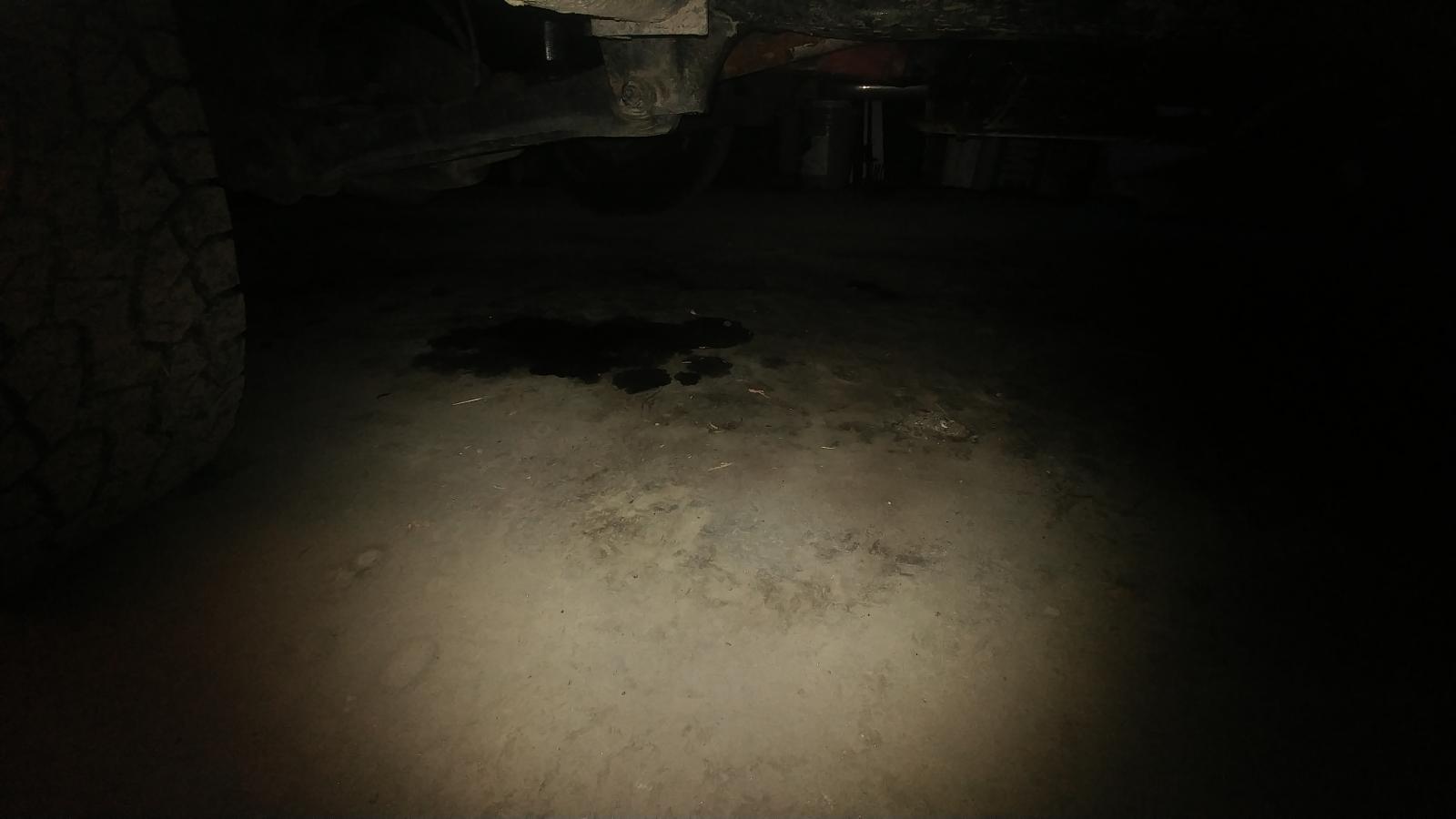
Let it drip. Catch can just make a bigger mess. When it fills up and sloshes around. Never worked in the front of the engine why would it work on the back of the engine. Still a broken idea.
-
The truck will function without an IAT sensor. You can delete the grid heater all together still start and run normally. Common in the south. All the important ground are hooked to the passenger side ground terminal. Flashing WTS light is a bad news deal that points to internal ECM problem. Booting issue or EPROM issues. Mostly caused by excessive AC noise from the alternator.
-
I don't suggest EZ because of circuit board issues. There known for water getting in the module and failing. If you going this route don't go above RV275's. That will be the cleanest you can do. Oh, be aware early series of ECM don't like being flashed too much with a Smarty S03. Some ECM's have been known to fail. Then you take the risk of being locked out and not being able to start your truck then have to pay $150 buck to recover your ECM. One of the few Smarty issues it does happen.
-
You'll be stuck with stock injectors. Can't adjust timing or fuel maps. Quadzilla Adrenaline and Smarty Touch are the only two tuners that allow for cleaning burning 7 x 0.010 injectors. Edge Juice and Edge Comp are very dirty with +50 HP and above. I've got an Edge Comp and its a smoke bomb with 7 x 0.010. It was a smoke bomb with 7 x 0.0085 injectors. Canned tuners are junk on anything bigger than stock. Timing is for sure wrong fuel map way too smoky. I'll admit on stock and RV275's wasn't bad. Starts getting smoky with +50 HP. There is no way to use large injectors on Edge product. S03 is also stuck to fair small injectors and very limited timing control. If you ever got down here to Idaho I'd straighten that out in a mere few minutes.
-
Change the Maximum fuel stretch down towards 1,200. TPS Max should be 100 TPS Min should be 0 Minim pump tap fueling should be 0 Pump low boost scale PSI go from 10 up towards 15 Boost scaling should be 40 Another is number of power level change it from 7 to 11. Now turn down the power level to mellow the hit. Try a Smarty Touch it's even more complex and crazy.


