Chris O.
Unpaid Member
-
Joined
-
Last visited
Everything posted by Chris O.
-
I am pretty sure your abs is acting up because of the tire revolutions per mile mile not set correctly.
-
As far as I know Dana80 Hybrid axle regardless of gear ratio has 120 tone ring tooth count. Sorry guys the tool is on hold until my job and health issues are solved.
-
Set the multimeter at the ohms (symbol Ω), look for (1600Ω - 2300Ω).
-
Well it could be the wiring harness, measure the resistance directly on the real ABS sensor first. https://youtu.be/HRvhzrsEQ28 CODE 37 - Intermittent Signal From Rear Sensor.
-
I did edit the post above with ABS connector and multimeter picture. GLOSSARY OF TERMS: ABS antilock brake system CAB controller antilock brake CCD Chrysler Collision Detection DLC data link connector EBC electronic brake controller EMF electromotive force (generated voltage) HCU hydraulic control unit IC integrated circuit NVRAM non-volatile random access memory PDC power distribution center RAM random access memory RWAL rear wheel antilock ROM read only memory WSS wheel speed sensor WHEEL SPEED SENSORS: The EBC 325 ABS system uses one wheel speed sensor on each front wheel, and one speed sensor mounted in the rear axle for the rear wheels. The EBC 2 used only one speed sensor mounted in the rear axle for the rear wheels. The sensor measures the wheel speed by monitoring a rotating tone wheel. The signal generated by the sensor and tone wheel is transmitted to the CAB. Each sensor has: * a magnetic/coil pick-up (speed sensor) that is mounted to a fixed component * an air gap between the tone wheel and the speed sensor assembly As the teeth of the tone wheel move through the magnetic field of the sensor, an AC voltage is generated. This signal frequency increases or decreases proportionally to the speed of the wheel. The CAB monitors this signal to check for a sudden change in single or multiple wheel decelerations. If the deceleration of one or more wheels is not within a predetermined amount, the antilock module takes control. Diagnostically, the coil of wheel speed sensors have different amounts of resistance based upon the sensor type. When measured across the connector two terminals, the resistance should be: 4x4 front sensor 893-1208 ohms 4x2 front sensors 1800-2200 ohms All rear sensors 1600-2300 ohms.
-
This is from my CCD bus tool notes. When Monitored and Set Condition: REAR SENSOR OPEN When Monitored: Ignition on. The CAB monitors the wheel speed circuit every 7 milliseconds (ms). Set Condition: If the CAB detects an open or shorted wheel speed sensor circuit, the Diagnostic Trouble Code (DTC) will set. POSSIBLE CAUSES: REAR WHEEL SPEED SENSOR OR CONNECTOR DAMAGE INTERMITTENT DTC REAR WHEEL SPEED SENSOR (+) CIRCUIT SHORTED TO GROUND REAR WHEEL SPEED SENSOR (-) CIRCUIT SHORTED TO GROUND REAR WHEEL SPEED SENSOR SHORTED TO GROUND CAB - INTERNAL SHORT OR OPEN REAR WHEEL SPEED SENSOR (+) CIRCUIT OPEN REAR WHEEL SPEED SENSOR (-) CIRCUIT OPEN REAR WHEEL SPEED SENSOR (+) CIRCUIT SHORTED TO VOLTAGE REAR WHEEL SPEED SENSOR (-) CIRCUIT SHORTED TO VOLTAGE REAR WHEEL SPEED SENSOR CIRCUITS SHORT TOGETHER REAR WHEEL SPEED SENSOR RESISTANCE OUT OF SPECIFICATION Measure the resistance across the Rear Wheel Speed Sensor (+) and (-) circuits at the CAB connector. Is the resistance 1600 - 2300 ohms? When Monitored and Set Condition: SYSTEM CONTROL MODE TIMEOUT When Monitored: Vehicle in antilock control mode. Vehicle speed above 6 km/h (4 mph) for 2 seconds. Set Condition: When monitored conditions have been satisfied for 120 consecutive controller checks spaced 1 second apart. POSSIBLE CAUSES CAB - NO RESPONSE TO INPUT BRAKE LAMP SWITCH BRAKE LAMP SWITCH SENSE CIRCUIT CAB INTERNAL FAULT ACTION: in Inputs/Outputs, read the Brake Lamp Switch state. Apply and release the brake pedal. Does the Scan Tool follow the pedal position?
-
For DODGE 2nd-gen, PSC Motorsports: https://www.pscmotorsports.com/vehicle-specific-products/dodge-truck-steering/94-02-full-size-p-u/1994-2002-dodge-ram-2500-3500-conversion-ram-assist-kit-stage-1.html
-
Yes - but not recommended, oil pressure sensors are designed for 0~100 PSI range - Fuel pressure 0~30 PSI range.
-
Reprogramming 1997-2001 Jeep Cherokee Gauge Clusters I bet this will work on Dodge RAM.
-
Correct CUMMINS INSITE software, connected to cummins bus (CAN bus, 3 pin connector by injection pump) EDIT: On 1999 connector location close to the injection pump, newer trucks probably have this connector closer to the ECM.
-
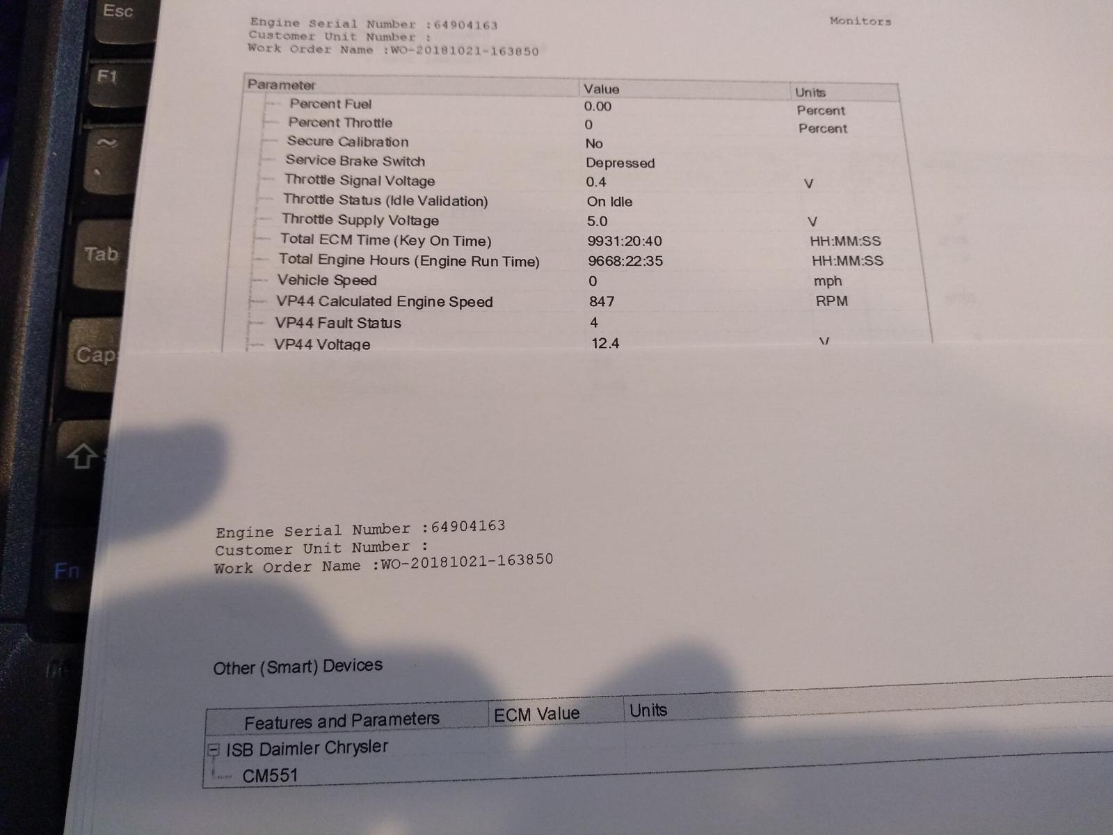
CUMMINS INSITE Engine Diagnostics Software: My truck @ 352000 miles mostly Highway ~ total engine hours = 9668h-22m-35sec.
-
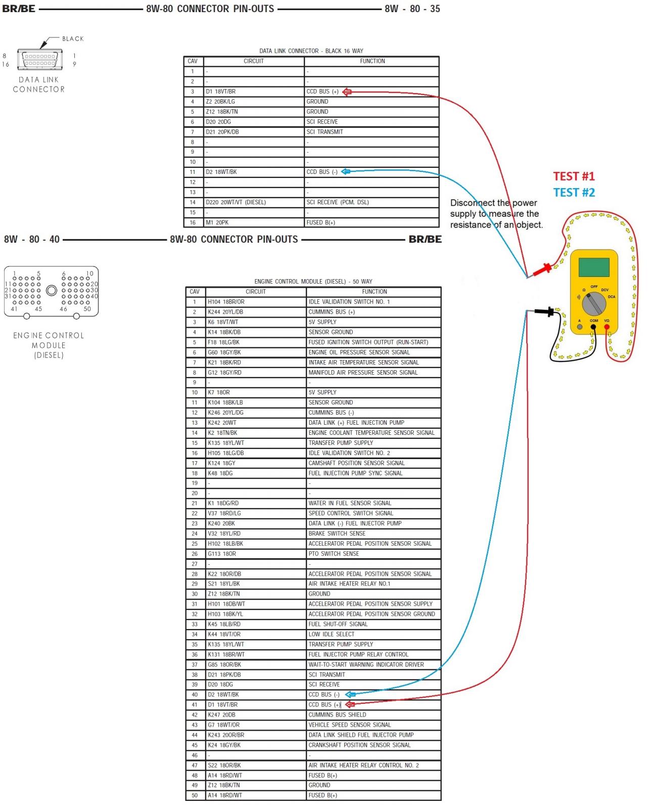
Try a simple test of resistance between ECM plug CCD BUS + - and ODBII data link connector (DLC) CCD BUS plug + -. -> (SEE PIC.) Look for resistance with less than 20 ohms (Ω).
-
If you do have Infinity factory radio and steering wheel volume control buttons then the buttons are connected to Highline or Premiumline Central Timer Module (CTM), the CTM relays the buttons commands to the radio via the CCD Bus.
-
ECM hardware issue or CCD bus wiring issues between the rest of the CCD bus (PCM, EMIC). I was just checking my CCD bus data logs and the RPM message comes from ECM on Cummins diesel application and on gas engine applications it comes from (JTEC) PCM. This message also contains boost information. This is the same message that the Electro-Mechanical Instrument Cluster (EMIC) needs for the RPM gauge.
-
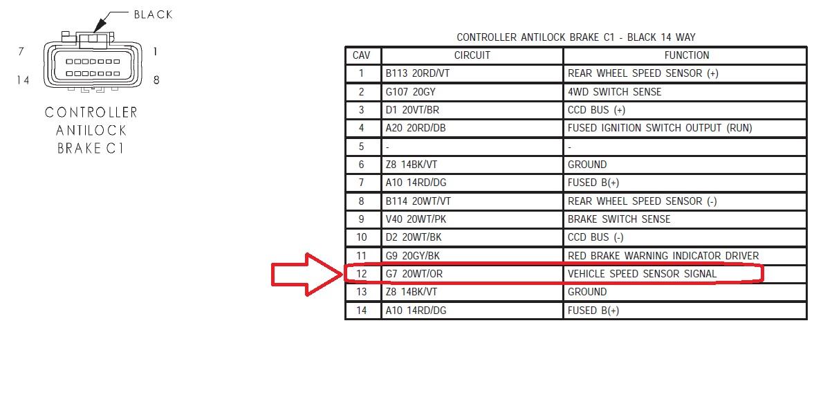
Oh I see I don't have Quadzilla, I was under the impression that you guys use ELM 327 Chip device for the tablet. No matter what you still need the PCM for the speedo. Connector pinouts in service manual pdf @ page # 1014. ABS to PCM wiring connection: All the wiring will be on the ABS bigger connector, leave the smaller connector(s) unplugged. Here is the PINs # you will need connected: 1 B113 20RD/VT REAR WHEEL SPEED SENSOR (+), (Connect to speed sensor on top of rear differential) 3 D1 20VT/BR CCD BUS (+), Connect to PCM, ECM, EMIC 4 A20 20RD/DB FUSED IGNITION SWITCH OUTPUT (RUN), Ignition on 6 Z8 14BK/VT GROUND or 13 Z8 14BK/VT GROUND 7 A10 14RD/DG FUSED B(+) or 14 A10 14RD/DG FUSED B(+) 8 B114 20WT/VT REAR WHEEL SPEED SENSOR (-), (Connect to speed sensor on top of rear differential) 10 D2 20WT/BK CCD BUS (-) , Connect to PCM, ECM, EMIC 12 G7 20WT/OR VEHICLE SPEED SENSOR SIGNAL, (Connect to PCM) For racing I don't think you will be running factory tires Strongly suggest connecting CCD bus to Data link connector (pin 4 - 5 GND, pin 16 BAT+, pin 3 CCD+ and pin 11 CCD-) ODB II Type A SAE-J1962 connector for programming ABS Speedo calibration.
-
The problem is OP is trying to use tablet/quadzilla for tach and speedo, this can only work with PCM through Connector pin 7 on DLC ODB II Type A SAE-J1962 connector and this is using one of the five ODB protocols available at that time (in 2nd gen truck 24v-ISO 9141-2 bi-directional bus) mandatory federal government On-board diagnostics. Now don't confuse this ODB bus with Chrysler trade secret property diagnostic SCI or CCD bus, no PIDs Parameter IDs on SCI bus or CCD.
-
INSTRUMENT CLUSTER FAILURE MESSAGE: 920 The cluster is not receiving a vehicle speed message from the PCM. 921 The cluster is not receiving a distance pulse message from the PCM. You can disconnect Central Timer Module for testing just to rule it out, unless you have alarm enable the truck should start no problem. Sounds like Issues with PCM, have you seen (NO BUS) message on the instrument cluster ?
-
2nd Gen Dodge Ram Cummins 24 valve minimum computer list required: ECM, PCM, ABS (CAB - Controller Antilock Brake), Electro-Mechanical Instrument Cluster (EMIC). At least one electronic control module on the data bus must provide a voltage source for the CCD data bus network known as bus bias (Instrument cluster provides CCD voltage bus bias).
-
Oh I just re-read the tread, I thought you guys are talking about map sensor. Beer probably isn’t helping here either
-
Not entirely correct: 99 RAM CUMMINS is reporting 0 psi @ IDLE, There was software update on Cummins diesel ECU Between 2000 - 2001.5 which shows true atmospheric pressure 14.70 pounds per square inch @ sea level. my 2¢...
-
Time for http://www.fostertruck.com/dodge/starters/rebuild-kits.html I was @350000 miles when I did it, excellent rebuild kit
-
Nope, only lurking on the forums from time to time Just been too busy reverse engineering CCD bus in our truck, Like today I just figured out which digit of VIN number is responsible for ABS code 84 VIN mismatch ): 5th VIN Digit. Vehicle Line B - Ram - Wagon/Van, ASCII dec 66 C - Ram Cab Chassis/Ram Pickup 4x2, ASCII dec 67 F - Ram Cab Chassis/Ram Pickup 4x4, ASCII dec70 G - Dakota/Sport 4x4, ASCII dec71 L - Dakota/Sport 4x2, ASCII dec76 R - Durango 4x2, ASCII dec 82 S - Durango 4x4, ASCII dec83 Thanks to my special ABS fooler
-
Me too I also have Mitsubishi Starion 87
-
Nice build. Question: is that Mitsubishi Starion or Dodge Conquest in the back on this picture?
-
@Mopar1973Man this is actually incorrect the PCM is sending the speed signal on CCD bus and it gets it from Pin 12 on ABS connector. Dodge 1999 RAM Cummins 5.9L NV4500 5spd. ABS sensor signal from the rear differential @ 6 Mph. (YELLOW) pin1+ and pin8- @ abs connector. Out to PCM (BLUE) pin 12 @ abs connector.