


Chris O.
Unpaid Member
-
Joined
-
Last visited
Everything posted by Chris O.
-
Amen to that, i bet your Radio is eating up more battery on standby.
-
Another option is GENUINE OE new switches. This one is for the overhead console with ( trip computer ): https://www.amazon.com/Overhead-Console-Wiring-Switches-GENUINE/dp/B00B7MWNOQ And this one is for overhead console ( without the trip computer ): https://www.amazon.com/1999-2002-Overhead-Console-Wiring-Switches/dp/B00B7MW0T4/ref=pd_sim_263_5?_encoding=UTF8&pd_rd_i=B00B7MW0T4&pd_rd_r=VPPX2102MEGMAK72CZ40&pd_rd_w=699X4&pd_rd_wg=6sK92&psc=1&refRID=VPPX2102MEGMAK72CZ40
-
I hope not that should be plug-and-play and easy to follow menu, just like most of the modern OBD scan tools. Now my neighbors must have thought I was on drugs, when i was testing the HORN RELAY for 2 hours like an IDIOT @ 10pm.
-
No PCM flushing is necessary or any other ECM or Control Modules flashing needed. Just finished CTM Actuator menu testing.
-
Yes that's the idea but for the trucks already with overhead console it will be plug and play. For truck that don't have overhead console installed by factory, a wire harness will be necessary to be installed, the harness will enable you to make most of the connections needed.
-
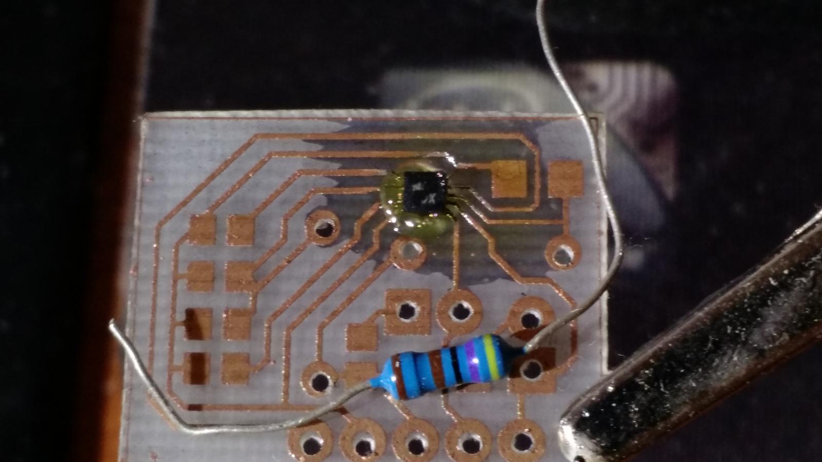
Yeah me too. @SilverMoose - np man I'm busy too. With my boss recent death(1.5m ago), even my full-time job is in a limbo. Well I only work for these guys since 1995, i'm probably going to have to look for new job soon after New Year's. On the bright side I did try to implement digital compass, also need to redesign the main motherboard for the new microcontroller i have in mind, get new power supply figure out with auto shut down if there is no CCD bus activity. Here I am testing the digital compass and TFT brightness control: At least the necessary parts are coming in for the beta test: Here I got the triple axis magnetometer breakout MAG3110 compass chip solder for testing.
-
PM sent ...
-
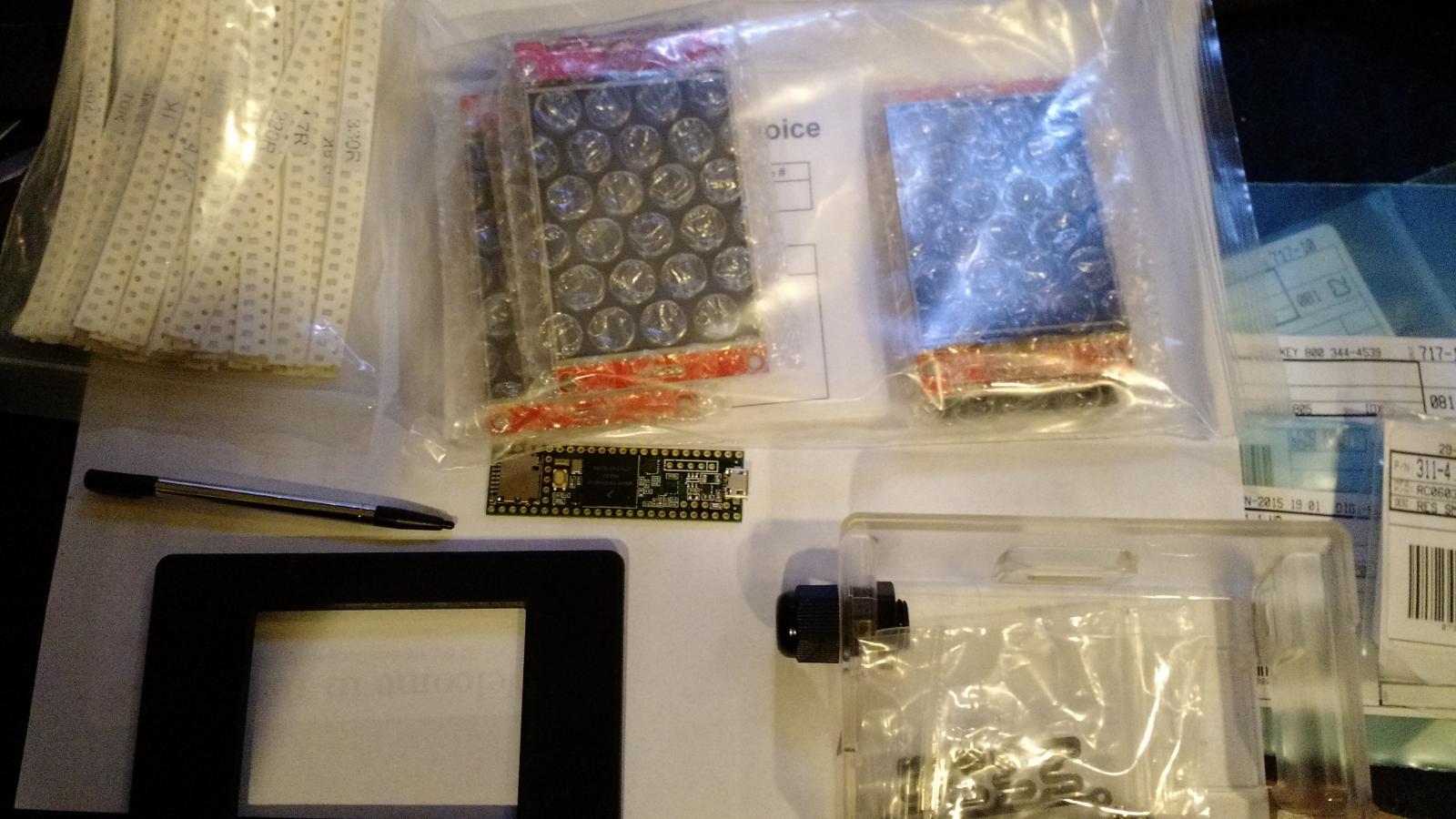
Well we just got one more member for the beta test Dripley. So I've been thinking about some cheap enclosure project box i could get from Amazon or digikey. And just connect to the DLC diagnostic port, this would speed up the project a bit, at least for the beta test. All we really need is 4 wires, the ground and the +12 volt ignition On [i don't think that's available on the DLC] and the two (CCD Bus +) and (CCD Bus -) wires.
-
Both of you are on my list. On the side note you would be include even if you said no, you guys help so many folks around that is not even funny. Just for that you deserve something out of the forum community, so as many other great active members on this forum.
-
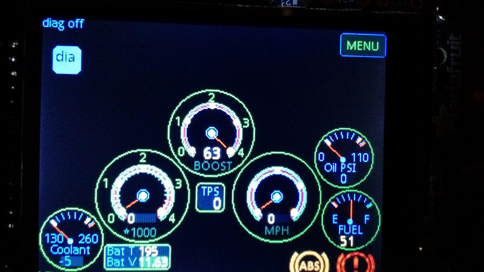
Yeah it's not ready yet but i'm going to need beta testers. Anyone interested ( Me78569, Mopar1973Man )? @ Mopar1973Man I don't think I'm even gonna bother with the fuel rate calculations Lie-O-Meter. .I still need to implement the clock and inside outside temperature, fix details with the gauges. I'm also wondering if there is fuel temperature on the CCD bus?
-
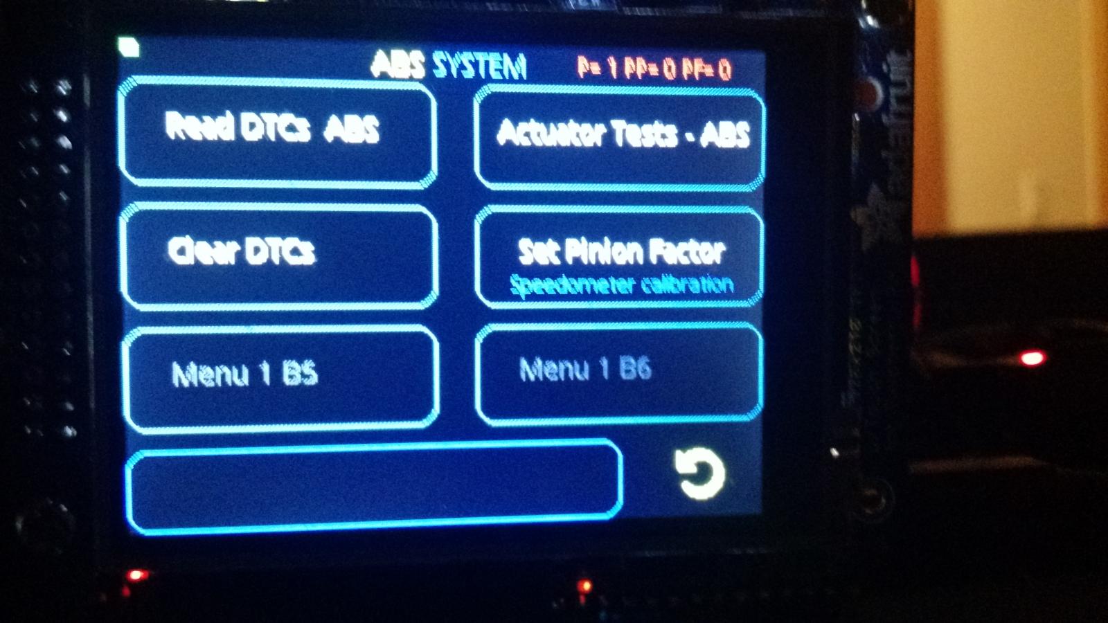
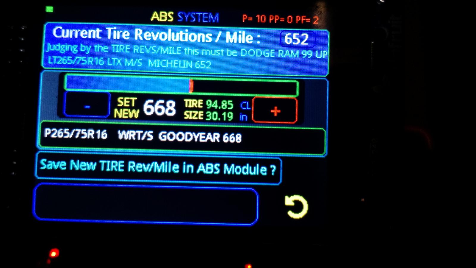
I think I solved my issue. Long story short this is for my upcoming CCD bus OverHead gauge project. I actually had a small bug in the coding which I believe is fixed now, just need to take the truck out for test-drive. By the way i just implemented Tire Size Calculator in the CODE, auto calculates tire diameter and circumference based on a tire revs/mile.
-
I'm just curious if you guys have any issues with your speedometer when you compare it to GPS speed. I own my truck since 1999 and the speedometer was always off by about 5 miles when traveling at 70 it's actually 75. I've been looking into the Chrysler shop manual and this stuff doesn't give me the correct tire revolution per mile, WTF? Chrysler Shop Manual section 22. TIRES/WHEELS 22. BR/BE TIRES/WHEELS 22 - 9. SPECIFICATIONS TIRE SIZE SUPPLIER REVOLUTIONS PER MILE P225/75/R16 XL GOODYEAR 716 P245/75R16 WRT/S GOODYEAR 692 P245/75R16 LTX A/S MICHELIN 691 P265/75R16 WRT/S GOODYEAR 668 LT245/75R16 LTX A/S MICHELIN 679 LT245/75R16 LTX M/S MICHELIN 678 <--- My DODGE RAM 1999 was set to this ? LT265/75R16 LTX A/S MICHELIN 648 LT265/75R16 LTX M/S MICHELIN 652 <--- Currently running this tires and I'm still off. LT275/70R17 WGSA GOODYEAR 650 LT235/85R16 WAP GOODYEAR 650 LT235/85R16 LTX M/S MICHELIN 650 Now I have a question if you guys have any issues with your speedometer or did you calibrate your speedometer with some type of programmer (Smarty, Chrysler DRB III or Hypertech ?).
-
I'd say it will happen, the question is when. Also we need mopar1973man security forums up and running.
-
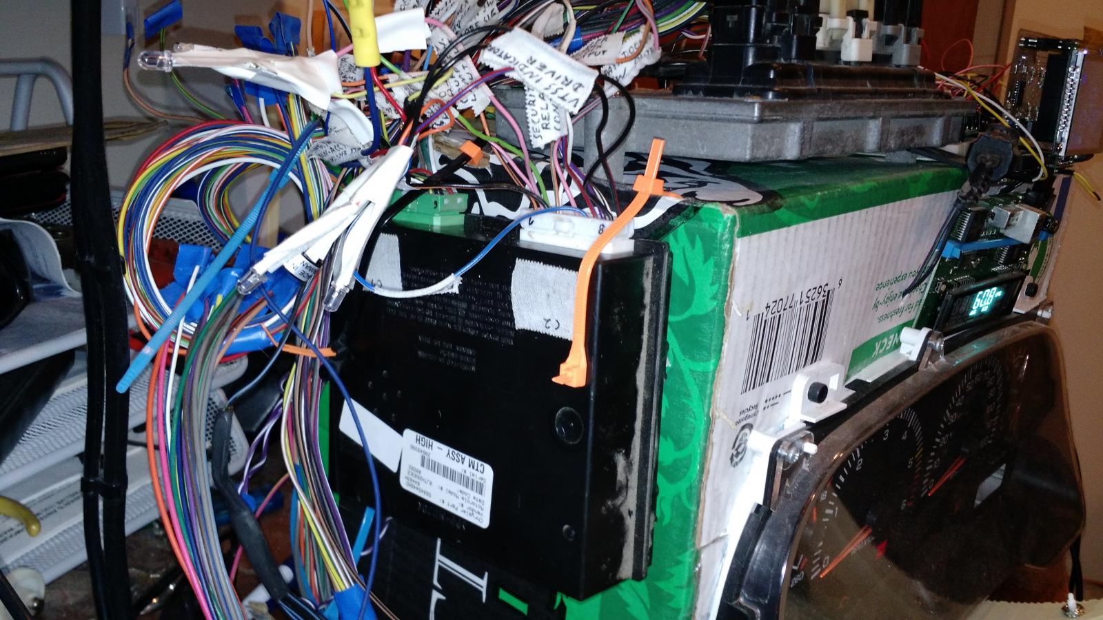
Well I'm not there yet, about a week ago I was able to get High line CTM (CENTRAL TIMER MODULE) from salvage yard for only $10 ): I'm actually hacking into it as I'm writing this, the issue is i don't have the key fob for this CTM module, and i just managed to wire this CTM up, this can be a huge mess. I just like to point out be careful trying out any used High line or Premium line CTM module. And here's why you can actually find this info online:
-
It all appears to be correct as the voltage and termination resistor. I don't see any issues here it's probably one of the connectors maybe loose. Check the connectors and chassis ground on PCM, also check the connectors on instrument cluster Gage. I would also check the big connector with the white plastic and a bolt in the middle of it above the brake pedal close to the fuse panels. Don't forget to disconnect the batteries before you mess with the connectors.
-
When testing the CCD bus wires (pin 3 and 11) when probed with pin 5(or chassis ground) must have 2.5 volts each, at KOEO(Key On Engine Off). If you don't get 2.5 volts at the CCD bus wires, check pin terminal connectors going to the following CCD modules: central timer, radio, instrument cluster, air bag, ABS, overhead console. You can also monitor pin 3/11 with battery disconnected and expect to get 60 ohms* there. *Note: 120 ohm termination resistor While at least one termination resistor is required for the system to operate, most Chrysler systems use two. The second termination resistor serves as a backup. If not, disconnect the CCD modules one at a time until ohmmeter reading returns to normal.
-
Pretty informative video, Cummins Injector Testing.
-
I have no issues removing ball joints with this tool. https://www.amazon.com/OTC-6297-Ball-Joint-Separator/dp/B0015PN010/ref=pd_sim_263_1?ie=UTF8&pd_rd_i=B0015PN010&pd_rd_r=XFS4R7H1QRD8QDB8RF3V&pd_rd_w=DG2BX&pd_rd_wg=Js0gy&psc=1&refRID=XFS4R7H1QRD8QDB8RF3V
-
Okay. Security forum, someone please call me ):
-
No not really, you can remove the PCM. The body control module, abs, cluster gauge, ecm, still can talk to each other. There's just one problem: Bus Bias And Termination. The voltage network used by the CCD data bus to transmit messages requires both bias and termination. At least one electronic control module on the data bus must provide a voltage source for the CCD data bus network known as bus bias, and there must be at least one bus termination point for the data bus circuit to be complete. Now I'm not sure if the PCM is supplying the voltage source or the cluster gauge? The messages on the CCD-bus are flowing in a series a bytes. One message is typically 3-6 bytes long. They are repeating the same thing over and over barely changing the bytes. Essentially the communication is done via sending sequence of numbers between 0 and 255. Every message starts with an identification byte (ID byte). The closer it is to the zero the more important information it holds. In case of message collision (two modules are trying to say something at the same time) the message with the lower ID value wins the bus.
-
It is sort of bi directional communication. Cannot communicate between each control modules at the exactly same time. For example if you connect scan tool, you can send specific message to the ABS(CAB) asking for DTCs codes. But the reply will be on the next message transmitted from the ABS(CAB).
-
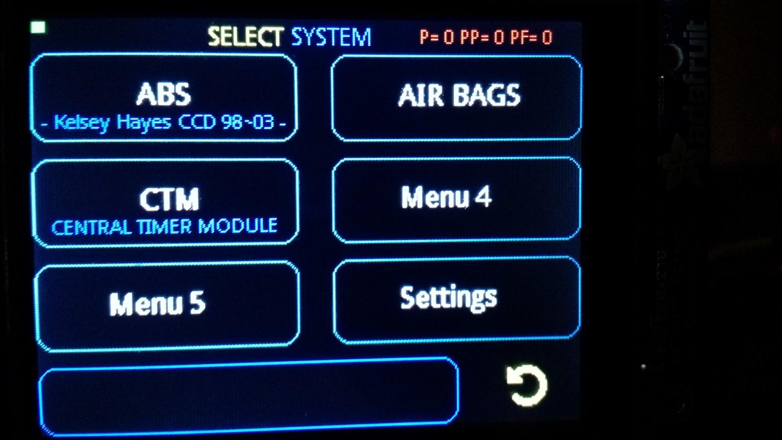
NO YES Let's start with some info about CCD bus first. CCD bus system was introduced in 1988 (end-of-life about 2003). The Chrysler Collision Detection (also referred to as CCD or C2D ) data bus system is a multiplex system used for vehicle communications on many Chrysler Corporation vehicles. Within the context of the CCD system, the term “collision“ refers to the system’s ability to avoid collisions of the electronic data that enters the data bus from various electronic control modules at approximately the same time. The Chrysler system allows an electronic control module to broadcast message data out onto the bus where all other electronic control modules can “hear” the messages that are being sent. When a module hears a message on the data bus that it requires, it relays that message to its microprocessor. Each module ignores the messages on the data bus that are being sent to other electronic control modules. On the CCD bus: The Controller Antilock Brakes (CAB) CAB is listening to VIN number messages from Powertrain Control Module (PCM). (Only few of the Vehicle identification number characters) CAB is listening to diagnostic scan tool messages. (Reading codes, Activate the ABS solenoids and pump , Speedometer calibration) ABS(CAB) On the CCD bus Is only sending one message once every one second, Status message. (Control of the lights in the Cluster gauge ABS, Brake, 4WD Lock, Brake switch sense etc.) If the ABS(CAB) Status message is missing on the CCD bus the Cluster gauge will illuminate the amber ABS light.
-
I'm not sure if this video will be of any help. Dodge 1999 RAM Cummins 5.9L NV4500 5spd. 2WD ABS sensor signal from the rear differential @ 6 Mph. (YELLOW) pin1+ and pin8- @ abs connector. Out to PCM (BLUE) pin 12 @ abs connector. In my never-ending quest of reverse engineering the CCD BUS i spent a lot of time with the ABS unit. Anyway your issues seems to be the programming of the PCM. It seems that the frequency of the differential rear speed sensor should be divided by 10 and that will give you the nice square wave frequency. EDIT: Ok so I did some math it appears to be 25Hz per mile. formula: 25Hz x 40mph = 1000Hz To get what the PCM requires We're going to divide 1000Hz \ 10 = 100Hz
-
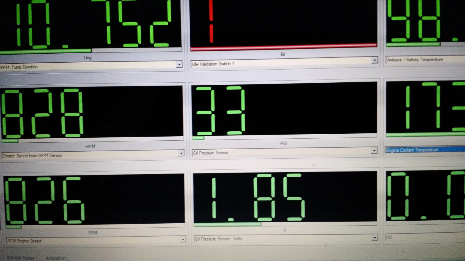
Mike is correct on the CCD BUS, that's how the cluster gauge knows how to show the oil pressure. Now I believe the problem is the OBDII compliance in our diesel truck OBDII used to be only for vehicles <8500 lbs GVW. They raised it to 14,000 in 2004, our diesel trucks where not required to be OBDII compliant. But anyways I can definitely read the oil pressure with my scan tool. It could be a different PID but the oil pressure is definitely available thru ISO9141-2, SCI BUS
-
I can read the oil pressure with my scan tool. I'm not sure how accurate it is but at 29 PSI the cluster gauge shows 40 PSI. EDIT: Perhaps this will be useful to some of you with the odb2 scanner. PID 2541 Oil Pressure Oil Press Pressure 0 100 1 Y OilPres DCx Sensors n none I got that info from: http://www.cherokeesrt8.com/forums/131-wk1-tuning-cmr-dyno-datalogging-gauges/19781-i-finally-got-around-listing-pids-dashhawk-can-see.html

