Tractorman
Yearly Subscription
-
Joined
-
Last visited
Everything posted by Tractorman
-
Personally, I think there is too much emphasis placed on turbo cooldown. An example of where turbo cooldown is needed is where one might be towing up a grade with the engine under a heavy load for several minutes. Suddenly, traffic comes to a stop and is going to remain stopped for awhile. In this case, a 5-10 minute cooldown is wise, not just for the turbo, but for the engine as well. You would do the same with your car's gasoline powered engine. The rest of the time - probably 95% of the time - by the time one pulls into their destination (store, fuel station, home driveway) the cooldown has already occurred. Very good point (and they don't come with an EGT gauge, either). If a stock truck and a 500 hp truck were pulling an equal load at 65 mph, they are essentially using the same horsepower (neither one near their rated horsepower) and generating the same amount of heat. By the time both trucks exited a freeway and arrived at a fueling station they will very likely have cooled down sufficiently to shut down the engine. Years ago I was a shop supervisor for the Copper Mountain Resort vehicle maintenance department in Colorado. The International truck used by the purchasing department was powered by a DTA466 diesel engine. There was an EGT gauge in the dash. This truck made about 3 trips to Denver each week. Occasionally, we started getting complaints from businesses in Denver about this truck idling for an hour or so in front of a business during the summer months. After talking with the three different drivers, one driver said the EGT's never fell below 300° and he didn't want to damage the turbo. He told the other drivers to let the engine idle to save turbo. We instructed him and the other two drivers to shut the engine off right away at businesses and educated them on the rare occurrence when idling for a few minutes before shutdown would be necessary. Then..., we removed the EGT gauge. I am not expecting to change anyone's thoughts on this topic, but I like to provide information as to why something is done in a certain manner. - John
-
I have a friend who drove and 07 Cummins for a few years. The first several months he owned it, I would notice a ticking / knocking sound when he started the engine and let it idle. He said he couldn't hear it. I said we should investigate it some time. Anyway, it took awhile to get around to it. It was a loose clamp on #4 injector line. Tightened the clamp - noise gone. He said, "Oh, it is quieter now". I think the #4 injector line or the clamp was upgraded for the 3rd generation common rail engines. Might have been a bad day for Mopar1973Man, but at least the fuel didn't catch fire. - John
-
Just recently (in March) I installed a Centramatic Wheel balance Kit (for 4 wheels) on my truck. Same idea, just a different product. The photo below gives you an idea of how they are mounted and how they work. Six ounces of ceramic beads are contained in synthetic oil in in the outer ring. The manufacturer states that the beads begin to distribute themselves at road speeds above 30 mph. I tried this product for a reason. Last summer I purchased four new Blizzak tires for my truck. I had them mounted and balanced at a local tire place. Afterward, I drove about five miles on the freeway on the way home - the ride was smooth. The last half mile to my house is a gravel road. I checked the tires when I arrived home and noticed the tread was full of rocks. When I drove the truck the next day, I observed that only about half of the rocks were shed from the tread. Of course, the rocks affected tire balance. I could feel the tire vibration at different speeds, but especially at about 68-70 mph. Bummer, because I like the tires. Anyway, I drove the truck a couple of months that way while pondering what to do about it. I settled on the Centramatics. I liked the idea that the ceramic beads are contained in a clean environment immersed in synthetic oil so they would be effective in cold climates as well. It was a $220 investment, but I am happy because they work!. Since the quantity of rocks stuck in the tread is everchanging, the continuous dynamic balancing takes care of the vibration. I have not tried removing the weights at this time, but I may do that at some point. I would be nice not to have to balance tires on a regular schedule. W-T, I enjoyed your post. - John
-
For a minute I thought @wil440posted those pictures. I couldn't figure out how he got to Idaho so fast. Then I realized it wasn't him. He posts his photos upside down. Cool back country! - John
-
Driving on the wrong side of the road..., posting pictures upside down..., isn't that normal for the folks in the UK? It is hard to imagine setting sail in the year 1620 from one country to another country that one had never been to before. - John
-
Ether is only bad for an engine when used improperly. This is why I recommend sliding the intercooler boot back at the air intake connection on the driver side of the engine. The ether spray will atomize and quickly get to the cylinders in a vapor state. Be sure to disable the VP44 injection pump by pulling the fuel pump relay in the PDC before you do the ether test. You do not want fuel being injected when performing the ether test - it would skew the results. Don't forget to disable the grid heaters, as well. Let us know the results. @wil440, thank you for your assistance. - John
-
This isn't the answer I was looking for. The term "turning over" usually refers to the starter motor cranking the engine over. What I want to know is when you injected ether and the engine started running, did it run smoothly and evenly on all cylinders? This observation is important. If it did run smoothly and evenly on all cylinders, then you do not have a problem with the head. If it did not run smoothly and evenly, and sounded like your description of how your engine is idling now, then you do have a problem with the head. - John
-
When the engine did start, did it sound like it was firing evenly on all cylinders? If it did, then you definitely have a fuel problem. If it sound rough, it would mean that you have a mechanical problem. It might be worth it to run the ether test again. I would disconnect the grid heaters, remove the fuel pump relay in the PDC, and slide back the boot on the intake (driver side) to supply the ether. Applying the ether here will reduce the distance to the cylinders for the ether to travel. If there is no blockage in the intake and exhaust manifold, and the engine is mechanically sound, the engine should start and run smoothly on the ether. - John
-
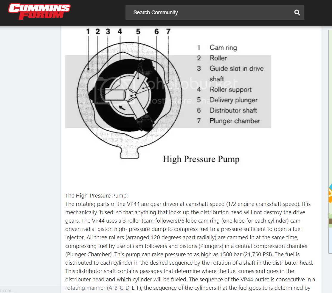
Good. That is important to know. I don't think you have an injector problem since you have put good working injectors into cylinders that are not firing and you have seen no change in operation. Viewing the diagram below I cannot see how the VP44 could fail in a manner to lose the three back cylinders on the engine. It doesn't mean it is not possible, it's just that I don't see it. - John
-
I went back and reread this thread (twice now). From what I understand, this engine was running fine before the head replacement. You have done many things to diagnose this problem, like removing and re-installing injectors many times. From my own personal experience I have found that I have caused a problem that didn't exist before I started a repair. When this happens, I go through all of the possible things that I could have done to cause this. I also repeat fundamental steps of troubleshooting in order to isolate or prove that what I conclude is true. If your engine was running okay before you started this project, then it would be highly unlikely (possible, but highly unlikely) that one-half of the VP44 would just quit working when your repair was completed. So, with that in mind: * Could it be that a rag got left in the intake manifold that could be not allowing air to enter the last three cylinders? How about a rag in the exhaust manifold? At this point I recommend (as I recommended earlier) since the engine does run, perform the injector isolation test for each and every cylinder to prove for absolute certainty which cylinders are contributing and which cylinders are not. Either get a wrench or make a wrench that will allow you to loosen each injector line one at a time at the head. - John
-
Probably just looking at you makes her tired. One thing about your part of the world - buildings that are hundreds of years old. Simply amazing! - John
-
The things we take for granted in the USA. I couldn't imagine crossing a border and having to drive on the other side of the road in a vehicle that wasn't designed to drive on the other side of the road. I added Sittensen to the map. - John

-
So, I placed some yellow pins on the map. Does this resemble your trip? If it does, it looks like it would be a fun trip. Enjoy! - John

-
I believe he is referring to the upper and lower control arms. At this point I would have someone operate the steering wheel to repeatedly make the noise. I would crawl under the truck and with use of a stethoscope I would start checking every possible place that steering linkage or suspension components are connected to the frame or another component. Don't rule out a frame crack in another location. Components that are fastened by bolts, nuts, or rivets can leave a tell-tale sign of component movement. If there is a well defined dark line where components mate, this could indicate movement. Usually, a thin layer of road grime will cover this area if there is no movement. Keep in mind that you may be certain that a sound is coming from a specific location, but in reality the source of the sound could be from an entirely different location. Once, I had a Ford 1/2 ton truck that had a popping sound coming from the front passenger side. I could turn the steering wheel from stop to stop and make it pop. I spent lots of hours trying to figure it out. A few months later during a routine maintenance inspection, I noticed that a rivet on the transmission crossmember had a dark line where the crossmember joined the frame - turns out the rivet had lost its full clamping force. I had my wife operate the steering wheel and I could feel movement between the crossmember and frame when the popping sound occurred. I replaced the rivet with a hardened bolt, washer and nut. The popping sound from the front passenger side was gone and never came back. You'll find it... - John
-
With the engine running and truck parked, can you operate the steering wheel back and forth to make the popping sound occur? - John
-
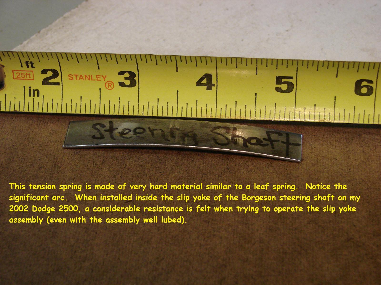
@YeaImDylan, excellent job providing information! I would inspect that steering shaft closely, especially since your are feeling the pop toward the top of the steering box and especially after it would fix itself for awhile after being worked on. Years ago I replaced my original steering shaft with a Borgeson steering shaft. A thousand miles or so later the steering developed a popping noise that I could feel in the steering wheel. The feel was very subtle. It took me 25,000 miles of driving to figure out the problem. It turned out to be the slip yoke (sliding portion) on the new steering shaft. Each time I would work on the steering, the problem would go away for a few days or a few hundred miles, but it always came back. You can see in the photo below the arced spring that was used. That spring (even well lubed) intermittently would stick and not allow for axial movement of the shaft. That was the source of the popping sound. I had to removed that spring. The steering has performed flawlessly for over 120,000 miles since. This may not be your problem, but it clearly shows that some steering problem symptoms can be very hard to diagnose. Take some time to diagnose and pay close attention to cause and effect, don't just change out parts. - John
-
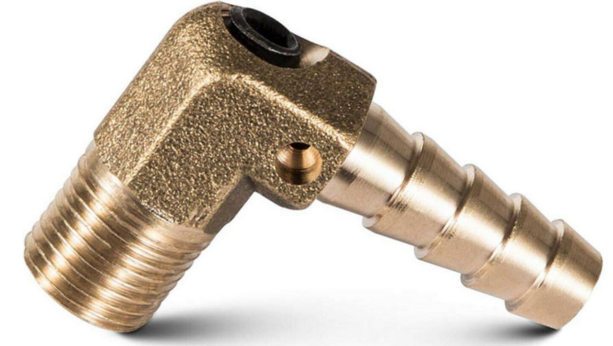
The drilled hole is a vent and it is needed to make the boost elbow work. If there is no vent, the boost flow can be restricted, but air will eventually fill the wastegate actuator chamber resulting in no change of wastegate operation, other than the wastegate will take a bit longer to open. The drilled orifice is downstream of the adjustable restrictor. The orifice will also act as a restriction, but as pressure builds the flow leaving orifice to atmosphere will match the flow passing through the adjustable restrictor at some point. When this happens, the new pressure value acting on the the wastegate actuator will now be lower than the actual boost pressure value of the air entering the boost elbow. The wastegate will not open. Yes, this is true. Exhaust flow that enters the turbine housing is exposed to some of the area of the closed wastegate valve. That area can be calculated by measuring the diameter of the exposed area. Example: Formula to calculate force. Diameter squared times .7854. (D2 x .7854) Let's say the exposed diameter of the closed wastegate valve is one-half inch. .5 x .5 x .7854 = .19635 square inches. I will round that to .20 square inches. Multiplying .20 square inches by 50 psi (turbine drive pressure) will equal 10 lbs of force pushing against a mechanical spring. The same method can be used to calculate the force of the wastegate actuator rod under a specific boost pressure. - John
-
I am interested to hear the results. - John
-
More questions than answers... What front end parts were replaced and why? What was wrong with the old steering gearbox? So, two steering boxes were installed? When did the popping sound begin occurring (relative to repairs)? Before? After? in the middle? How many miles on the truck? on the steering parts? Has the steering shaft ever been replaced? I doubt that the steering gearbox is making the popping sound. - John
-
This is not surprising as marine engines have a lot more constants than truck engines have regarding air supply. For example, an ocean going vessel's engine has atmospheric pressure and air temperature surrounding it that is relatively constant. The engine is designed to move a load that will allow the engine to operate efficiently in a constant rpm range because the engine load is relatively constant. Consequently, the turbocharger can easily be sized for a marine application that will keep the turbocharger in its efficiency range without risk of over speeding the shaft - so, no wastegate needed. Truck engines on the other hand operate in more extremes of atmospheric pressure and air temperature - atmospheric pressure from sea level to over 11,000 feet in altitude, temperature from lower than minus 50°F to over 120°F. They also operate under load within a wide engine rpm band - from just off idle to a high rpm repeatedly during each gear change in the transmission. With tighter automotive emission standards, smaller turbochargers were introduced because they could supply more air into the engine's cylinders at much lower engine rpm's. This made diesel engines perform better throughout the rpm range, thus improving engine performance as well as improving emissions. To control a smaller turbocharger from over-boosting or over-speeding, a wastegate was added. I think you would be okay to use any of the methods mentioned in previous posts. I don't think there would be a significant difference in EGT's or drive pressure at 40 psi boost whether the wastegate was open or not. There are only so many oxygen molecules available to use in a given parcel of air at a given pressure and temperature to aid in the combustion process. And, of course, this whole post is just my opinion. - John
-
Or, just disconnect and plug the boost line to the actuator. Put a cap on the actuator side to keep out dirt. Use the tuner to set maximum boost. - John
-
A hand operated vacuum pump is a great tool for diagnosing vacuum leaks. You should find a small vacuum manifold with many connections just above and nearby the top of the valve cover. Locate the line that goes to HVAC unit. Unplug that line and connect the vacuum pump to it. Operate the vacuum pump. After several pumps the vacuum should easily rise to 20" HG or more and hold when you stop pumping. If you cannot make this happens, you probably have found your problem. All vacuum operated HVAC systems default to defrost (for safety) when the vacuum supply is lost. As I am writing I just realized that in my first post I mentioned there could be an electrical problem as well, but after thinking about that - it is not the case. All door functions are controlled by vacuum actuators. The only exception is the blend door actuator; it is controlled electrically. - John
-
More questions than answers. When and under what conditions did you first notice the ABS and brake warning light? the abnormal AC operation? How many times has this happened? Are the symptoms consistent? Noting that when the trailer was disconnected and the truck was driven and the ABS and brake light went out may not have any value. When an ABS lamp is lit, it will not reset until the truck is driven a certain distance above a certain speed (usually a short distance and less than 25 mph). If this problem is intermittent, the light could go out on its own, regardless of the trailer wiring connection. This condition could occur from a moderate vacuum leak or a lack of an electrical signal to carry out the command. If you turn of the engine and restart the engine two or three times, do the symptoms repeat? Thoroughly check for vacuum leaks. If possible, use a vacuum pump to supply the HVAC vacuum line only and see if the problem persists. - John
-
Just curious, you didn't mention checking cylinder # 2, #5 and #6 - did you check them? Or, maybe you did check them and just didn't post the results. Checking all cylinders by loosening the fuel line and then documenting the results would be more conclusive than just checking some of them. The more specific relevant information you provide will likely lead to resolving the problem sooner. I have mentioned performing this test on all six cylinders in a previous post, but I have not seen any posts from you stating that you performed the complete test. If you did check all of the cylinders, let us know what the results were. - John
-
Huh? Spring? - John Yesterday... This morning....