Jump to content

Welcome To Mopar1973Man.Com LLC

We are privately owned, with access to a professional Diesel Mechanic, who can provide additional support for Dodge Ram Cummins Diesel vehicles. Many detailed information is FREE and available to read. However, in order to interact directly with our Diesel Mechanic, Michael, by phone, via zoom, or as the web-based option, Subscription Plans are offered that will enable these and other features.  Go to the Subscription Page and Select a desired plan. At any time you wish to cancel the Subscription, click Subscription Page, select the 'Cancel' button, and it will be canceled. For your convenience, all subscriptions are on auto-renewal.

Posted
  • Popular Post

After 18 years of interesting CTD enthusiasts and transmission specialty outlets all contributing their method, or fix, to the well known TC lock unlock syndrome, I can no longer remain silent.


Extensive review of many posts regarding TC lock unlock, the rerouting methodes, the add on filters for APPS and last, but not least,...the "tin-foil hat" brigade. I do realize that each individual or company that contributed to the vast amount of information on the web had good intentions and I must acknowledge that some of the procedures caused me to closely examine what these people were trying to do. I believe it is well known that even a blind mouse occasionally finds a morsel of cheese.


Again, as it is well known @Mopar1973Man  was the only entity who positively identified the instigating source of this key issue. My entry today is not about alternators...it is about what Daimler/Chrysler did in regard to production of these Cummins powered platforms and the complete disregard of common sense Electronic Engineering.  Please note, this applies to automatic and manual transmissions as each platform is plagued in the same manor with different quirks. 

image.png.438b4aa021a7881563be0485c0fff17b.png

IMG_0231.JPG.08ee70c74847798f0ad2336d0ba86a7f.JPG 

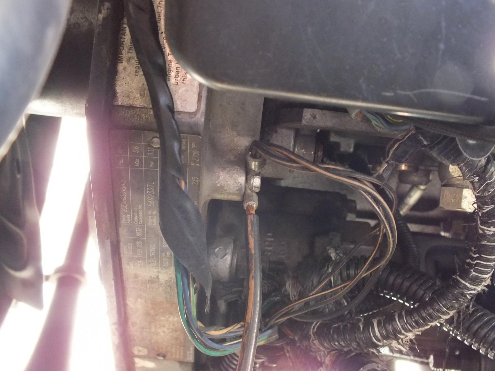
This Blk/Tan #8 gage wire is quite critical in the scheme of things. It is contained within a 1" plastic conduit passing along the front of the engine. It contains water temp sensor leads, air conditioning leads, alternator/PCM leads and the #6 gage alternator charge line to the PDC. This #8 gage Blk/Tan passes over the top/backend of the alternator and is "eventually" connected to the Auxiliary Battery (passenger side) negative terminal.


image.png.367fb01e914fafa927ab6f33bb00e02c.png

This snapshot of the Factory Service manual documents "four critical ground leads" that are "spliced" in an unconventional method.


IMG_0232.JPG.f78fef6507b5b69435e7830179194478.JPG

image.png.b3b425cc11edb3b1bf18df900695c201.png

This photo depicts the three #18 gage wires and the single #14 gage wire entering the shrink-tubing where the "crush-splice" occurs. This bundle exits the large plastic conduit below the VP44


image.png.18e9aaba150e4cbc751b29f801fe692d.png

This again is a most disturbing depiction of the Daimler/Chrysler method of splicing critical ground leads and then routing this across the top of the alternator and "eventually" bringing this to ground reference. 


image.png.48d0cab05138ad02148f20b174e30c73.pngIMG_0232d.JPG.fa30ae61395e0f08898c6bf4ade9508b.JPG

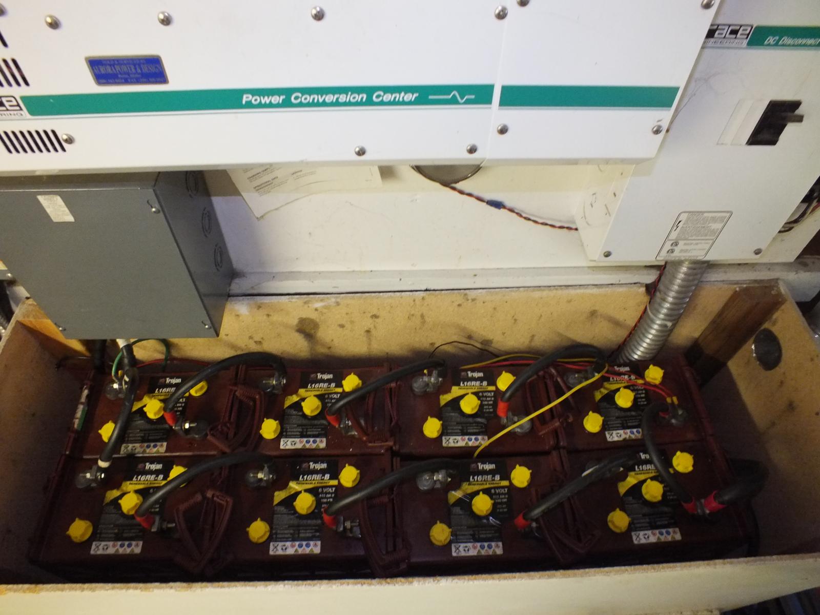
This photo depicts where this #8 gage Blk/Tan first connects on the way to "eventual" ground...yes this is the Auxiliary Battery tray connector. Please note: it is spliced again and joins the PCM circuit board grounds...which are critical in their own nature...and "eventually" terminate at the negative post of the Auxiliary Battery's negative terminal.  :doh:


IMG_0232c.JPG.09b23716f27d80cfcb4afc699f6ecec6.JPG

image.png.9928492012cf33e14535305aa46e523b.png

This photo is very interesting, it is the Factory Service manual and the assembly line documentation follows this as a road map in the matrix during production. Please NOTE the title "NAME" to each battery...I looked at this for a considerable amount of time before I realized the assembly line coordinators tried to work with the documentation from the Engineering Staff to "make it as it looks"...Could this single oversight be the reason of a four foot ten inch critical ground wire combination traveling the distance to "EVENTUALLY" terminate at ground? From a basic engineering standpoint regarding ground...you "NEVER CHOOSE THE PATH OF EVENTUAL GROUND" !!! 


It is to be the shortest and most concise connection in reference to ground...this is biblical in ALL ELECTRONICS...including pickup trucks. :( !


IMG_0233a.JPG.5acd3baf709f1f864ead8b3020dafa6c.JPG

image.png.c718f3292f0191de3b430102f1db108a.png

Here is the Factory Service manual documenting the PCM circuit board reference ground starting as a pair of #14 gage wires being spliced into a #10 gage bundle and arriving at the Auxiliary Battery through another connector that joins a #8 gage wire that is "splice-joined" under plastic conduit in a Y configuration joining the rouge #8 gage "after passing over the alternator" traversing the entire engine compartment from the driver side of the vehicle. Seriously :doh:


I have been drinking excessively, most recently, due to the nature of this blatant discovery.:sick:   


image.png.5ae0193ea13c924137bc2fb77b0b02b6.png

This is the hidden Y splice at the Auxiliary Battery where the "mess" EVENTUALLY terminates for ground reference.


IMG_0261.JPG.adb246a5ad8d7c1a9bb862cab92a9157.JPG

image.png.31dc759cba66b07592aad1179f80e287.png

This photo shows the correct "HOLE" of where to apply ground for the VP44, ECM and the PDC...note the logical location


image.png.4e33cef0693abeb9eb3fd7b7c1ae3ae6.pngIMG_0262.JPG.778cee524a51a1492c7d85557c2f9d60.JPG

It took a little research to find the size and proper thread-pitch.


IMG_0262a.JPG.bf460745b21883d43dd948c573d25e73.JPG

image.png.2dc9ff1a386e17e85234bf9d6060ecfa.png

Metric M5 with a 5/16" hex head is perfect


IMG_0263.JPG.7da0b3de1032b84d83fab0aa5d7f8ada.JPG

image.png.2f3062313c2c97656d6e4b65b33f7265.png

This is where you apply a fresh "quality" #6 gage ground and terminate this at the Main Battery negative post on the drivers side for absolute ground reference for the VP44 and ECM 


IMG_0264.JPG.5b668a7d3d4d3823cb43ecce21bf0ace.JPG

image.png.ccc6fb374c753eb2b86cfcfb13d29d24.png

This is a very short and concise reference to ground.


IMG_0265.JPG.defcbb47e0fda54a20a26dafca671aff.JPG

image.png.37171f3c48c398dbd7626baa718975d0.png

This is the corrected procedure for a rather critical ground.


IMG_0272.JPG.2de8079fcd9ea01b6b77180ceac58f25.JPG

image.png.2081c16c3c8bd38685c39c4c754541f8.png

The two largest wires originally contained within the 1 inch conduit are no longer present and located well away from the alternator.


IMG_0273.JPG.8299e7bf9dabbeeffdf5383fd76e2d5e.JPG

image.png.838b69661f3cff300dd8735d00a4fdc2.png

My alternator B+ "charge" line is now a #4 gage line directly connected to the Auxiliary Battery and when my new battery terminals arrive and they are secured, I'll provide photos of a completed Master Power Supply System within this engine bay. 


With these corrections, I would hypothesize that a poor ripple specification on a given alternator would be overcome by the immense capacitance of the parallel batteries and would become less prone to causing the dreaded TC lock/unlock for automatics and cruise-control abnormalities for the manual transmission platforms. 


The #8 gage Blk/Tan passing over the alternator as an "EVENTUAL" ground is gone...the PCM, ECM, VP44 and the PDC are now grounded in accordance of standard Electronic Engineering practices.


Respectfully

W-T  

Edited by IBMobile
spelling

  • Replies 206
  • Views 70.7k
  • Created
  • Last Reply

Top Posters In This Topic

Most Popular Posts

  • Part 2    I wish to apologize for my absence and attempt to clear some of the stress I may have created.   Members @GSP7 and @Dodgeih, my humble and sincere apologies.  

  • @Marcus2000monsterThanks, and the alternator is a DC Power Engineering XP 270. You'll be able to find them on the web and they are located in Riverside, California. It is a 6 phase large frame unit th

  • I've done mine already.  This is what I did. 1  Disconnect batteries   2  Unplug ground wirer, the one (black/yellow) that comes by the alternator, at the aux. battery.   3  R

Posted Images

Featured Replies

  On 6/17/2018 at 4:30 AM, JAG1 said:

The old VP I was pulling had a loose key. Took a pencil magnet and got it before I did anything else. New VP went very well no leaks and runs very smooth. I helped a lot to dab the white paint on the key.


Interesting note;

                  Just got done with W-Ts' Grounding mods and running the B+ charge wire to the passenger battery. Basically did everything on his list and my AC Volts are cut to less than half of what they were. I'm happy because it was really worth doing it. I used all copper wire marine grade wire and parts.:burnout:

What was your before and after?

  • Staff
  On 6/17/2018 at 11:53 AM, dripley said:

What was your before and after?

All I can remember was the level of AC noise was exactly right on the margin. Whatever that was and now its showing .021 A/C volts so it might even be better than cut in half. All I can say is like what you say, ''it was well worth it''. Makes a guy very happy to make progress like that.

I really enjoy running a new charge wire, too. The stock wire looked cooked. I noticed some disparity between voltages on each battery, so next is run 6ga wire from ground to ground across the radiator. Lowe's had the wire half off at the end of the asile. Big thick copper stuff, not soft strand.

  • Staff

Thought I should mention that I just got done today with W-Ts wiring mods on my second truck and the results are the same as the first one with AC ripple cut to less than half of what it was. Very happy with the results. Thanks to you W-T :thumbup2:

  • Staff

I tried the 5 mm bolt for the ground point on the timing gear case, and it was too loose and wouldn't tighten up at all. I bought a 6 mm bolt with the same thread pitch and it fit perfectly. I know W-T's thread says "5mm" but just thought I'd save some folks another trip to the hardware store.

  On 6/25/2018 at 2:36 AM, 99_Cummins_4x4 said:

I tried the 5 mm bolt for the ground point on the timing gear case, and it was too loose and wouldn't tighten up at all. I bought a 6 mm bolt with the same thread pitch and it fit perfectly. I know W-T's thread says "5mm" but just thought I'd save some folks another trip to the hardware store.

I used a 5mm on mine and it worked fine.

  • Staff

Both my trucks got lucky. I went thru my screw/ bolt bins and found only two, one for each truck. They tightened just fine. I recommend  screw by hand to see that it goes all the way without binding, making sure they are the right threads and length. Some out of my bolt bin would go about 2 turns and wasn't right. those would strip and be a real problem.

  • 2 weeks later...

Question, Did all you use 4 new positive and negative wires going to the main battery then to the auxillary battery using #2 gauge? Or did you just keep the original positive wire and do the rest of the mods?


Thanks!

If you go back and read what all @W-Thas in his truck you would understand why did all of those extra battery cables. His truck has high electrical demands due his radios and such plus a much higher output alternator.

 Personally I did not. I did a while back replace all my battery cables with 2/0 cable and I did run a ground wire from battery ground to battery ground, 4  gauge I believe. I did see a good reduction in the ac voltage prior to the extra ground wire but figured it could not hurt to run it, so I did. I just bought a pre made 60" cable from the parts store.

  On 7/7/2018 at 6:34 PM, dripley said:

If you go back and read what all @W-Thas in his truck you would understand why did all of those extra battery cables. His truck has high electrical demands due his radios and such plus a much higher output alternator.

 Personally I did not. I did a while back replace all my battery cables with 2/0 cable and I did run a ground wire from battery ground to battery ground, 4  gauge I believe. I did see a good reduction in the ac voltage prior to the extra ground wire but figured it could not hurt to run it, so I did. I just bought a pre made 60" cable from the parts store.

I did read all the posts, but was getting a bit confused on whether or not a person should replace or add the 2/0 cable is why I asked. It doesn't take much to confuse me when it comes to electrical stuff! LOL  Reading it I did notice  @W-T had extra accessories, but still wondered if it was necessary or worth doing and IBMobiles list did not include the 2/0 cable either, thus another reason for asking. Trying to get my ducks in a row.

  • Staff
  On 7/7/2018 at 5:35 PM, mopar440cu said:

Question, Did all you use 4 new positive and negative wires going to the main battery then to the auxillary battery using #2 gauge? Or did you just keep the original positive wire and do the rest of the mods?


Thanks!

I only did the rest of the mods like, your asking, to both my second gens. The results were very close to the same on both...... cut the A/C ripple to a little less than half what it was. Very happy this old guy got both done.

  On 7/7/2018 at 7:14 PM, mopar440cu said:

I did read all the posts, but was getting a bit confused on whether or not a person should replace or add the 2/0 cable is why I asked. It doesn't take much to confuse me when it comes to electrical stuff! LOL  Reading it I did notice  @W-T had extra accessories, but still wondered if it was necessary or worth doing and IBMobiles list did not include the 2/0 cable either, thus another reason for asking. Trying to get my ducks in a row.

I am with you on the electrical stuff. I did the 2/0 cable out of personal preference and was not that expensive. Made them myself out of welding cable with soldered terminal ends. Also used the military style battery terminals. Had about $120 in the whole deal IIRC. Did that before @W-T came out with that article. Check your ac voltage before and after and see what difference it makes. Mine went from .035 to .01.

  • Staff

A little bit off topic, real quick..... do I have to remove the starter to get to the ground behind it? And do you have to remove the Driver side battery to get to the ground underneath there also?


Edited by JAG1

LChecked mine before and after. Went from .035 to .015. 

  • Staff


  On 7/7/2018 at 7:14 PM, mopar440cu said:

but still wondered if it was necessary or worth doing and IBMobiles list did not include the 2/0 cable either, thus another reason for asking. Trying to get my ducks in a row.

   What @W-T was referring to is if you have a high output alternator (180+ AMP)  then join the two batteries with the extra 2/0 cables so that they act as one.  This will keep the batteries charged equally and the battery temp sensor does not get an erroneous reading from the main battery.

   If you have the stock 140 AMP alternator then one extra 2/0 ground cable between the two batteries will do.  I have not added that to my truck yet.


  On 7/7/2018 at 7:46 PM, JAG1 said:

do I have to remove the starter to get to the ground behind it?

I did.


  On 7/7/2018 at 7:46 PM, JAG1 said:

do you have to remove the Driver side battery to get to the ground underneath there also?

I think so. 

  On 7/7/2018 at 9:37 PM, IBMobile said:

If you have the stock 140 AMP alternator then one extra 2/0 ground cable between the two batteries will do.  I have not added that to my truck yet.


Do you think 2/0 is necessary? I am pretty sure I used a 4 gauge and did see the ac go to about .009. Kind of fluctuates between .01 and .008.

Edited by dripley

  • Staff
  On 7/8/2018 at 12:02 AM, dripley said:

Do you think 2/0 is necessary? I am pretty sure I used a 4 gauge and did see the ac go to about .009.

That 4 gauge cable goes between the alternator's B+ terminal and the positive terminal of the auxiliary battery.

The 2/0 gauge cable goes between the negative terminal of the auxiliary and the negative terminal of the main battery.   This ties the two batteries together with out using the 0 gauge cable and engine block between them.


  On 7/8/2018 at 1:52 AM, IBMobile said:

That 4 gauge cable goes between the alternator's B+ terminal and the positive terminal of the auxiliary battery.

The 2/0 gauge cable goes between the negative terminal of the auxiliary and the negative terminal of the main battery.   This ties the two batteries together with out using the 0 gauge cable and engine block between them.


i used a 4 gauge for the charge wire from the alt to the passenger battery. I also used a 4 gauge to tie both batteries together on the negative side.

  • Staff

Way I understand it..... it just a supply of motivation that lacking. :poke:


Not surprised with the amount of traveling each week.

Did This Forum Post Help You?

Show the author some love by liking their post!

Welcome To Mopar1973Man.Com LLC

We are privately owned, with access to a professional Diesel Mechanic, who can provide additional support for Dodge Ram Cummins Diesel vehicles. Many detailed information is FREE and available to read. However, in order to interact directly with our Diesel Mechanic, Michael, by phone, via zoom, or as the web-based option, Subscription Plans are offered that will enable these and other features.  Go to the Subscription Page and Select a desired plan. At any time you wish to cancel the Subscription, click Subscription Page, select the 'Cancel' button, and it will be canceled. For your convenience, all subscriptions are on auto-renewal.