Jump to content
Posted

I recently fried my second ECM. It died in the same way as the last one. Stumbled will cruising around town and then died completely. It felt like the lift pump failed but the VP44 kept trying for a bit and then it stopped too. After getting it towed home I could get both the Fass lift pump and the injection pump to run (and the truck to idle) by bypassing the ecm but got no voltage signals from ecm to either lift pump or injection pump when trying to start the truck with e dry thing wired normally.


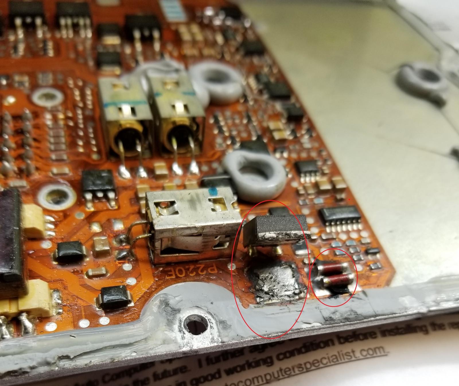
After reading the article here by IBM mobile about proper lift pump wiring, I believe the ecm failed because the relay that was used in the lift pump wiring didn’t have a diode which allowed the relay coil to back feed to the ecm and fry the lift pump circuit in the ecm. I believe I’m in the same boat as another thread’s poster as my instructions from Fass had me using the ecm lift pump feed as the trigger for the relay, but now Fass recommends using an ignition switched trigger instead. I will probably not use the ecm to trigger the lift pump with the next ecm (even with a diode relay) as I just don’t want to take the chance.
 

I want to really be as sure as can that this is really the cause because if I fry another ecm, I’ll probably drive the truck off a cliff. I have done the W-T mod and am in the process of upgrading all my battery cables and grounds, though they weren’t in that bad of shape. I have ohm tested the ecm’s power leads and grounds as well as the injectin pump’s ecm power and ground wires. All wire runs read less than 0.5 ohms. Anyone have any more suggestions to check?


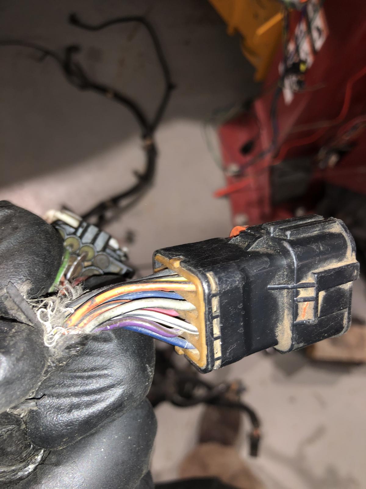
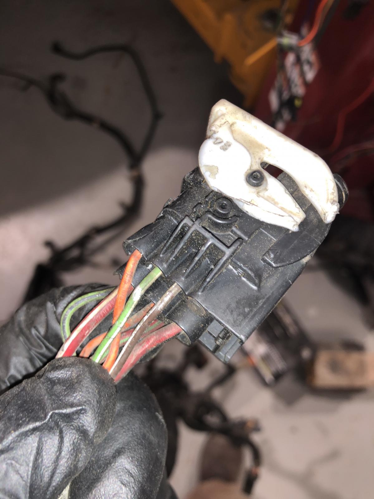
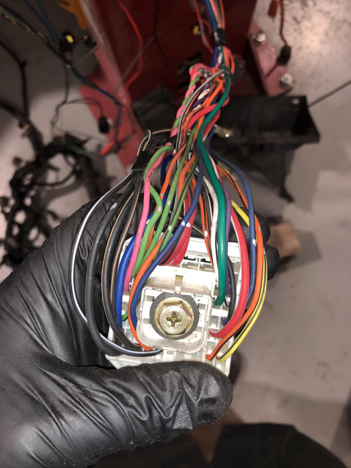
Also, while testing the vp44 connector’s wires back to the ecm and pdc, I noticed that my truck is missing one vp44 connector pin that goes to ecm pin 44. I am using the wiring diagram from here that is I believe either for a 1999 or 2000. My truck is a 1998. A pin out that I have describes the pin as “datalink shield injector pump”. Anyone know what this wire/pin is for? It doesn’t look like my truck ever had this pin as there are no extra wires in the harness. Thanks for any help anyone can give me.

Edited by the7t7

  • Replies 45
  • Views 16.7k
  • Created
  • Last Reply

Top Posters In This Topic

Most Popular Posts

  • You're doing a good job cleaning up the electrical on the truck.  Are you still waiting to hear from the ECM repair people about which part failed and what system it controls? Can you trace the c

  • I would wait for the results and in the mean time do other repairs.

  • That wouldn't do it.  The power to the fuel pump would be battery/PDC fuse, to relay terminal 30, to relay terminal 87, to fuel pump. In a proper installation the fuse would blow.   The ECM powers rel

Posted Images

Featured Replies

25 minutes ago, JAG1 said:


I wonder if the rebuilders would know a key wire to the ECM harness that would help protect the ECM by way of a protection fuse. Like the 5 amp fuse we install to the blue alternator wire. It just is something beyond me why we have to rely on such expensive circuitry that buns so often as is the case when we have to send them in to the rebuilders

You cant help but think there is something to share to help protect them from further damage. Seems they would have an idea of what caused the failure by seeing the damage. Seems the ECM is to remain mystery as well as what causes the issues other than "an electrical short".

  • Staff

I would have to say, like an electrical engineer once said, that a lot about circuitry is proprietary information to protect a companies interests. You would think a good rebuilder though, would give some helpful tips for protecting the ECM.


Perhaps another way of approach would be to ask, what are the ways a person could destroy an ECM if they actually wanted. It might help us to understand what circumstances arise that we need to be watchful of in our maintaining our trucks.


Dieselfuture has armor plate around his ECM :lol:

Edited by JAG1

  • Author
2 hours ago, dripley said:

You cant help but think there is something to share to help protect them from further damage. Seems they would have an idea of what caused the failure by seeing the damage. Seems the ECM is to remain mystery as well as what causes the issues other than "an electrical short".

I did ask them to test my old one. I think the holidays are slowing them down. I’ll check back with them end of week or Monday. 

Possibly they don’t want to tell us how to protect ECM as it cuts into their business 

  • Staff

I am sorry for getting off topic. You obviously have real trouble with your truck. You know a while back guys were talking about a hot headlight switch problem. Hot enough to melt wire insulation and even the switch itself, they were rewiring with a relay to let the switch trigger the power to the lights direct off the battery instead of thru the switch. I wonder if the trouble with your headlites is related in some way.

The big question is where is this short to ground causing the ECM to burn out. It can be difficult to isolate. However,  something I read awhile back.....that no voltage should show on your volt meter with both probes on the same wire. Weather a positive or a negative wire makes no difference, a good circuit will show no voltage if no leaks to ground and visa versa. A wire that has a problem showing a leak can therefore be isolated in this way.

   Im probably not helping as much as I would like.... please don't give up posting due to my getting off topic, Thank you, the7t7

Edited by JAG1

  • Author
1 hour ago, JAG1 said:

However,  something I read awhile back.....that no voltage should show on your volt meter with both probes on the same wire. Weather a positive or a negative wire makes no difference, a good circuit will show no voltage if no leaks to ground and visa versa. A wire that has a problem showing a leak can therefore be isolated in this way.

Not sure if I understand what you mean here. I believe I was doing this when I was looking for leaks in the pdc. However, I wasn’t checking voltage, since everything is disconnected from the battery now, and I have no ecm yet. I was checking resistance with one lead on the pdc positive supply side of the circuit in question and the other on body ground. Generally, the meter should show “open” on all circuits unless there is a short to ground especially with everything off. As I understand it, In resistance mode, the meter sends out a small amount of current through one lead and measures what gets returned through the other. I think most power gets used up powering whatever that circuit is for. Even with everything off, though, some circuits will show resistance and therefore a connection to ground if those circuits include resistors or elements like light bulbs, which are essentially resistors which shed light light when grounded. If I were measuring voltage, I think I would need the circuit powered to measure something like voltage drop.


2 hours ago, JAG1 said:

 Im probably not helping as much as I would like.... please don't give up posting due to my getting off topic, Thank you, the7t7

I actually got a good chuckle out of your emoji conversation with dieselfuture. I was actually going to make a joke like “jeez, you guys should get a room” but I’ve gotten in trouble with my sense of humor before, so I restrained myself.  I’m not giving up yet. I spent some time yesterday checking the fuel pump relay under load and heat (like with a heat gun and It worked ok) and pulling joint connector 1 and 2 to see if they weren’t damaged. I just didn’t find anything interesting. I’m going to recheck the ecm wiring today and if I don’t find anything maybe pull the harness to check the whole thing.


Thanks for all the suggestions and help. Even if they are off topic, it keeps me thinking bout it. 

  • Author

What’s so annoying about electrical problems to me is that after you check the obvious things, everything after that is ridiculously time consuming for someone who isn’t an electrical engineer. At this point I’m checking less common possibilities like connector failure or relay performance or intermittent scenarios. I spend most of my time trying to understand the wiring diagrams. It doesn’t help that my truck is a 98 and the first year of the 24v/vp44 and that the factory manual has supplements that add or replace the original diagrams. I have already found errors and inconsistencies between my truck and the manual, and the supplement and the regular diagrams, which makes it extra confusing. There is also slight differences between my 98 and it’s factory wiring diagram and the 1999 moparman wiring. For instance, some of the colors are wrong and some ground locations aren’t consistent. 
 

I also have a sneaking feeling that my truck is a very early 98.5 and isn’t exactly the same as later 98s or 99s. It was an auction truck at a used dealer with 160k miles so I have no idea about it’s history. At least it’s was stock with no mods other than a Fass factory location replacement lift pump (since upgraded to titanium) and an Oregon injection vp44. Anyway lunch is over, so back at it.

  • Staff

Let me see if I can write an example about testing with a volt meter.....


Say you have a stretch of positive wire that you want to check....... by placing the two probes anywhere along that line it should not show any voltage if a good wire without problems. Same thing with the two probes on a known ground wire, it shouldn't show any voltage when probes are placed on both ends of that ground nor anywhere in between. However, a wire that has a problem will show some amount of voltage since there is a leak along the line somewhere. I think this principle can help you locate a leak somewhere where as using an OHM meter mode can be confusing when there are sensors and other components hooked up. You have to be careful using OHMs because it can be very confusing and make you think a problem exists. You are not concerned with resistance so much, but finding leaks in the system is an important aspect  in order to find shorted circuits.


Hoping someone else can add to this because if you do find voltage running thru a wire that shouldn't have any voltage, I think there is a way to test, by moving the probs along that wire, exactly where the problem or leak exists.


Just remember with both probes on the same wire, not same circuit, but again the same wire, there should be no voltage if a good wire exists with no leaks.


I learned this from Dripley when he blew off every feather trying to do electrical. We have a picture floating around somewhere when that happened. :cummins:

Edited by JAG1

If the wood peckers would quit pecking holes in the wires..............

  • Staff
4 hours ago, JAG1 said:

We have a picture floating around somewhere when that happened. :cummins:

                                               5a7faf40c2a44_th3.jpg.23041982015a21555c72bc548325f066.jpg


You're doing a good job cleaning up the electrical on the truck.  Are you still waiting to hear from the ECM repair people about which part failed and what system it controls?

Can you trace the circuit from the fried component to the pin connector in the old ECM?  That may tell you the system that is causing the problem. 

  • Staff
3 hours ago, dripley said:

If the wood peckers would quit pecking holes in the wires..............

Around here its the ground squirrels making nests in there when you have the block heater plugged in all the time. Nice and warm and they like to chew the insulation off the wires.

Edited by JAG1

  • Author
3 hours ago, IBMobile said:

 Are you still waiting to hear from the ECM repair people about which part failed and what system it controls?

Can you trace the circuit from the fried component to the pin connector in the old ECM?  That may tell you the system that is causing the problem. 

Yes, they are apparently off for the holidays. I did get an email today that said they would get to it after the Holidays. I don’t know if that’s this Monday or Friday the 2nd or the next Monday. I do hope they can narrow it down for me. 
 

I did spend a bunch of hours today ohm testing every single ecm pin out to its source as well as further to common grounds and shared power sources. The cam sensor and crankcase sensor were particularly hard to get at. I didn’t check every single ccd bus connection but I did a few. I only found one bad connection. It was an ecm power connection to one of the grid heater relays. The connector itself had 40 ohms resistance through it even after I ran some sand paper inside it. The wire right after the connector showed low resistance. I’ll splice in another connector. I may even have an old solenoid connector that I can use, but if not, a ring connector will work. Probably not the source of my failed ecm. If it did anything, I believe that particular grid heater wouldn’t start.


Only thing I can think of left is an intermittent short that happens while moving ie vibration or abrasion. Removing the wiring harness and going through it might find something. Not sure if I should do that or wait for for results of old ecm test. I also need to do a front crank seal so might do that while I wait for results. 


  • Staff
22 minutes ago, the7t7 said:

Not sure if I should do that or wait for for results of old ecm test.

I would wait for the results and in the mean time do other repairs.

  • Staff
On 12/27/2019 at 5:52 PM, IBMobile said:

                                               5a7faf40c2a44_th3.jpg.23041982015a21555c72bc548325f066.jpg


Thanks IBMobile.... thats a good photo of Dripley while at the helm down there at the other ECM repair shop. :thumb1:

  • Author

I'm posting a little update since I'm still waiting on ecm diagnosis and its been a few days. I ended up removing the engine/ecm harness because it would always bother me that I didn't check it. In the interest of thoroughly checking everything, I'm also going to remove the vp44 and send it off to Oregon Injection (its one of theirs) and have them go through it, since I don't really know how many miles are on it. I'll do the tappet cover gasket at this time since its weeping a little. One of the things that make me think I have a weird early truck is that I have the 12V tappet cover with the crankcase vent on it. I do not have the crank case vent on the timing cover. I looked on the internet and couldn't really find any mention of this for 98.5s so not sure if its normal or not. On a side note, does anyone know the front crankcase breather would screw to my cover on the vp44 inspection hole? I could actually use more cranky ventilation since I have a compound turbo set up. I didn't have any leaks until I ran it on the dyno. Now I have front crank seal and tappet cover leaks. I'm thinking extra pressure from high horsepower dyno runs helped accelerate those leaks. I also noticed that I had a bunch of blow by when I did those runs when normally I don't have much.


Back to wiring. I also purchased a used 99 harness that has a couple busted plugs for $120 on eBay so I can compare it to mine. I should get this next week sometime. I have noticed a few things about my wiring that's different than what the 98 manual says and what the 99 mopar1973man diagrams say. For instance, my truck originally had the PCM grounds go to one of those passenger side ground plugs and then over to the engine (through alternator harness) to the ground at the front of the engine. When I did the wt-mod, I just ended them at the passenger side battery. The 98 manual says they go over the top firewall harness, through those 3 plugs high on the drive'r side, through the PDC and down to G100 under the driver's battery. My truck has those wires but they dead end at that high firewall plug and don't continue on to the PCM that way. 


If anyone is interested, I can take some photos of the harness (and my splice mods) since it's all cleaned up and ready to be rewrapped. Just waiting for ebay one for comparison.

@the7t7 Never hurts to see a mans handy work. FWIW the 02 wiring diagrams dont quite match what made it into my 02.