
Shainer
Unpaid Member
-
Joined
-
Last visited
Everything posted by Shainer
-
You pumping #2 diesel or 2# rocks through there? That sounds terrible, and a lot like physical interferences in the pump. What size fuse is on there? Ever blow one? Please tell me you installed the relay and not direct to the ECM.
-
I think we found the issue. Pump is no miracle worker and can only deal with so much air before being overcome and sending it to the IP. Air is being pulled in at the tank fitting, separated at the FASS, sent back via the filler tube, just to be aerated even more on the next suction cycle. Wouldn't take long to whip 35 gallons of diesel into a latte Starbucks would be jelly about.
-
Hmmm... Did FASS switch over to mostly quick connect fittings? You keep the factory fuel basket in the tank? My bet is your issue is on the suction side of the lift pump. The longer it runs the more aerated it makes the fuel. I when it starts acting up the lift pump is probably getting noisy as well but you may not be able to hear it. You could jumper the lift pump relay harness after the engine starts missing so you can listen to the pump with the engine off. The alternative is to disconnect inspect, clean, replace any quick connects on the suction side. Guys sometimes don't get the one on the tank seated, or while seating it get debris in it that allow air to enter.
-
I would not do that. If air intrusion is suspected the last thing you want to to is suck water and soap onto the fuel stream and send that to the IP and injectors. Besides you will never see a single bubble on any line under vacuum or pressurized fluid. Read Blue Chip's section on long crank times. He outlines air in fuel validation. Lets talk about the replacement lift pump. Is that in your signature? It has air separation? Where is the return line on the lift pump plumbed in? Did you replace all the lines from the tank to the IP? Quick connect on the tank?
-
What tests have you performed?
-
Yup process of isolating the issue. 9 out of 10 times it is related to prior components being messed with... and one guy didn't complete the survey. I look at it from the perspective of what if you replace the IP and the issue remains? Are you better off? Do you have more reliable data to isolate the issue, or did you add another handful of uncertain variables?
-
Have to be methodical and start proving systems out one at a time. If the symptoms are repeatable at idle you can crack injectors to try and figure out how many cylinders are impacted and try correcting the the injectors on those holes. If that doesn't change things or it seems like there is no consistent issue on specific cylinders I'd probably look for air in the fuel by adding a section of clear line. Actually walk through BlueChip's guides. No sense in me re-inventing the wheel. Only thing I will add is that in my experience issues tend to be related to components and systems a person has messed with. They make the assumption everything was done right, and never prove them out. https://www.bluechipdiesel.com/troubleshooting-1
-
Not proving much that we don't know. One or more cylinders are not firing correctly. If the miss is present at idle you can crack injector lines while it is running. Troubled injectors will not degrade the idle quality. Healthy injectors will. If you have two cylinders not contributing adjacent to each other in the firing sequence you can get a very rough engine.
-
My guess is the code was lift pump voltage out of range. It will self clear after a number of start cycles. I"m trying to think through what could be the trouble. Your issue sounds worse than just one or two injectors not sealing if it is bad enough to kill the engine when put into gear. Although it still seems like something is not sealed letting fuel bypass the high pressure side, or allowing air to enter the low pressure side. Why were the injectors replaced? Any drivability issues prompting the injector replacement? Do you have good fuel pressure when this occurs? Was a there a filter in between the failed lift pump and injection pump so trash didn't get sent to the IP? I seat the injectors in the bore. Seat connector tubes in their bore. While applying pressure on the connector tube I rotate injectors back and forth until I locate the spot where the connector tubes are inserted at the lowest point possible. This centers the connector tube on the injector body. Then I install the hold down with a bit of torque, then install injector lines with a bit of torque. Then I go back and torque the hold downs to final specs. Crank engine to bleed air out of lines and torque injector lines until fuel stops leaking.
-
I specifically stated the connector tube to injector interface ;-) O-ring has nothing to do with it. The only thing the o-ring does is keep the return fuel in the head so it can be returned to the tank. You could run the engine without the o-rings if you don't mind dumping the majority of your fuel out of the head and onto the ground. The connector tube seals to the injector body via machined surfaces, and forced deformation. Think of hard brake lines and flared fittings. When you tighten the injector line nut to the head, that nut is forcing not only the injector line onto the connector tube it is also forcing the connector tube onto the injector body. If the injector body was not properly aligned with the connector tube before the injector line nut is torqued down you may not have a proper seal. Or you may have a seal while cold, but as the components warm during operation the seal becomes compromised.
-
I had to go back and read your opening complaint. You have a few variables at play by now. Replaced injectors a few weeks back (is there a reason behind that?). LP died after injectors, and now a rough idle at OT. I think you have a sealing issue in the fuel system. If you have zero signs of external fuel leaks on the high pressure side of the pump to the head it may be the connector tube to injector interface. If that interface leaks injection timing and quantity will be incorrect. The misplaced fuel simply gets returned to the tank via the return and you are none the wiser. Also worth verifying everything is air tight on the low pressure side from the tank to the IP. Air ingestion will also cause timing and quantity errors, but I usually see that to be a constant issue, or worse durning initial start of the day.
-
Using a Bosh code reader available at Orileys. There is a bit of a trick to getting the whole picture. You have to tell the scanner to pull codes from both OBDII and something else (I don't recall the scanner verbiage). Basically if it doesn't pull the ECM data you only get the P1693. Same goes for clearing codes. You have to clear both the OBDII and the ECM or the P1693 will return. You can verify you are getting ECM codes by setting a water in fuel code by pulling the connector and briefly shorting the harness. It does not have to be active for the reader to pick it up. In my experience the ECM usually has WIF, or lift pump circuit out of range.
-
Think of it as compression fittings. As you tighten the injector line down it forces the injector line into the connector tube which is then forced onto the injector. If you are leaking externally and you have it cinched down pretty tight then you probably nicked the o-ring on the connector tube. #5 and #6 are not the most fun to play with so chances are a bit higher to damage the o-rings for those cylinders. With new o-rings those tubes should take quite a bit of resistance to get the connector tube to fully seat. Order a bag to keep in stock. https://www.amazon.com/gp/product/B005RUQRYQ/ref=oh_aui_detailpage_o00_s00?ie=UTF8&psc=1
-
For what it is worth I recommend just cutting the hard lines out. Leave enough on the pump end to serve as a nipple. Then order some silicone line from McMaster-Carr, Even vacuum hose from the parts store is better than the hard line. Route the replacement line to the driver side fender behind the battery, fuse block, etc then across the firewall. Those hard lines are asking for trouble as these rides age. I always hated how the factory rant the hard line straight through the engine bay. Always in the way.
-
Spanner wrench. In the pic there are bearing retainer/pre-load nuts with holes on the face. The dowels on the wrench go in the holes to tighten or loosen the nut.
-
I have around 240k miles on my MagnaFlow Pro-Series. PN 17924. No issues with it. Frequently get complements on the exhaust note without it being overbearing. Only thing I would change are the exhaust clamps. I'd spring for some of the longer 3" clamps. Better seal and less deformation.
-
No kidding? I was not aware of that, and now that I'm searching around I do see more incidents.. I thought about that as well. Was going to make the recommendation to verify valve operation. I"m not sure valve contact had to occur though since the valve may have been closed and the trunnion stopped all valve movement (it's the optimist in me).
-
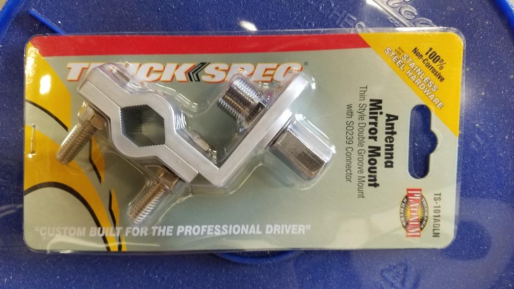
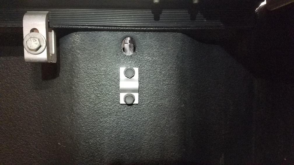
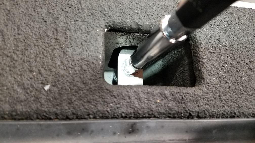
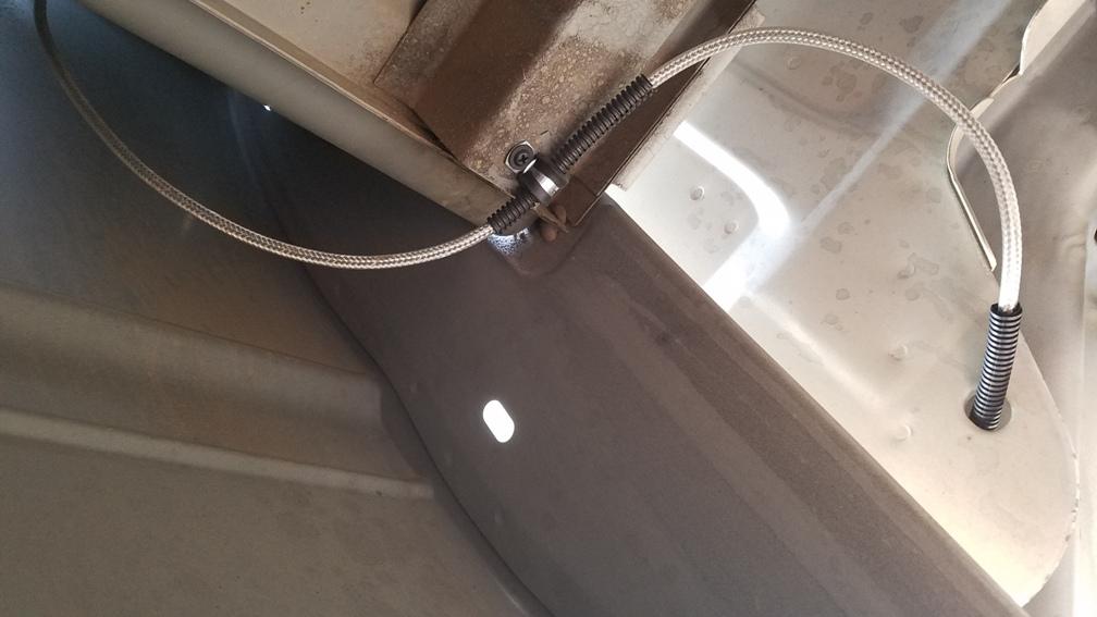
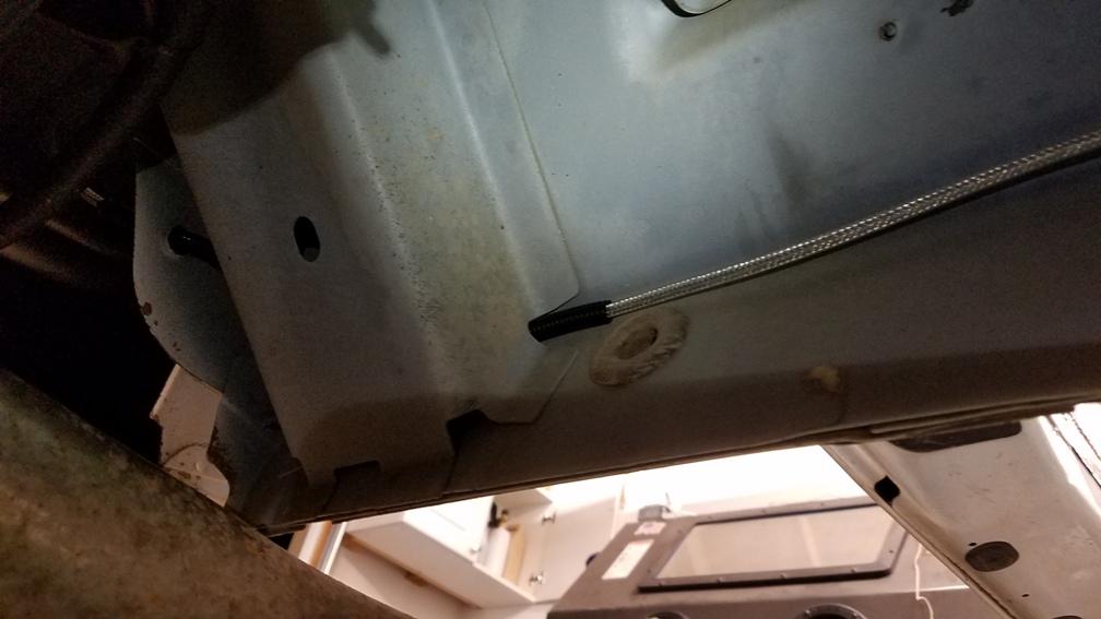
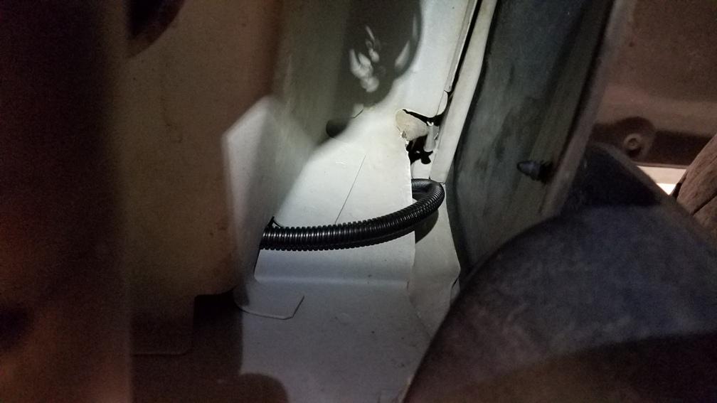
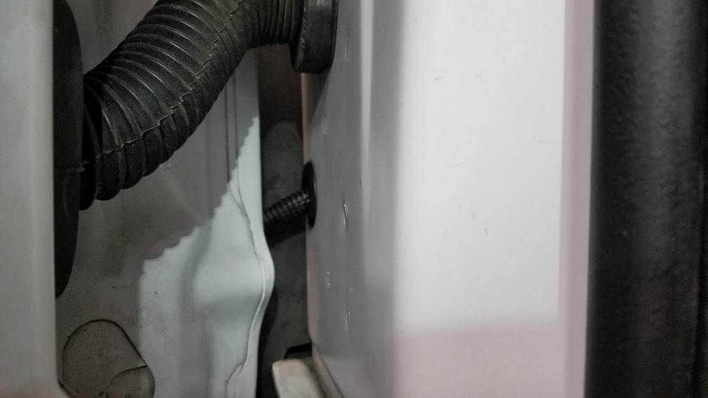
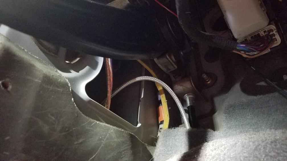
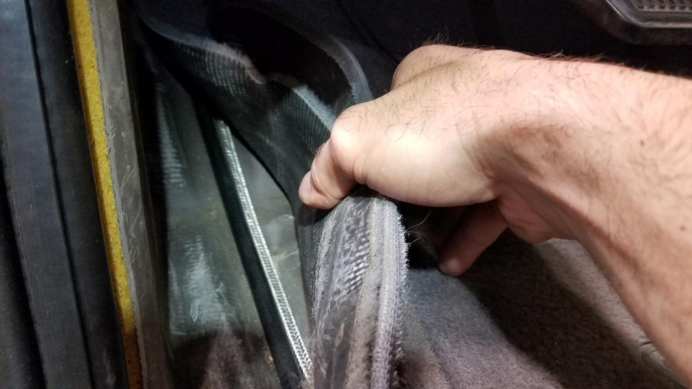
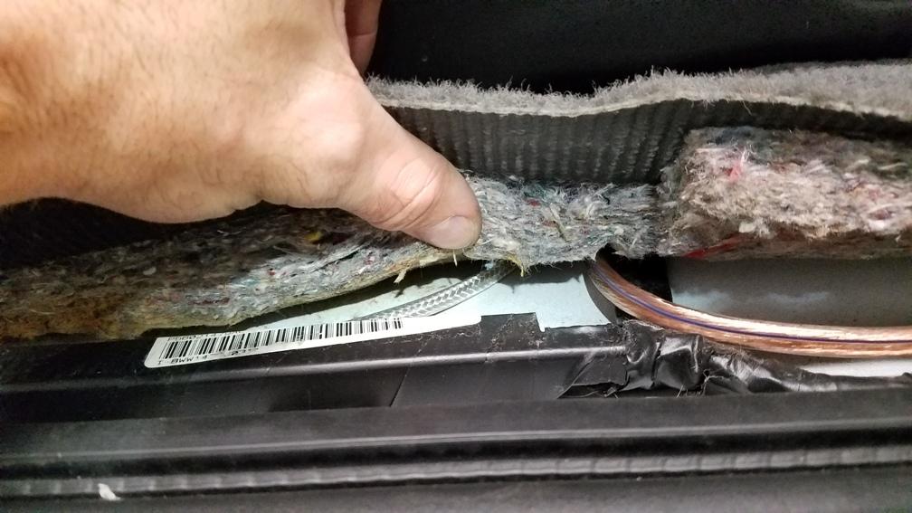
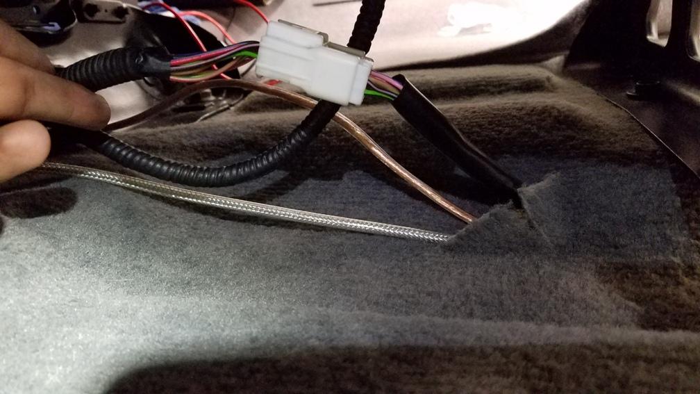
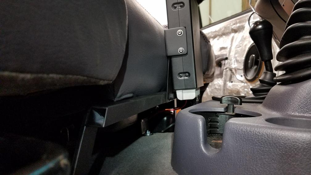
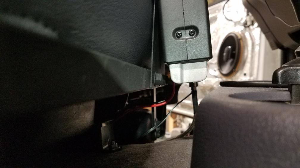
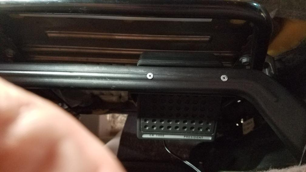
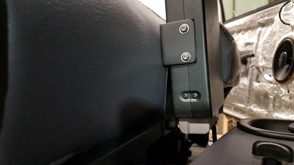
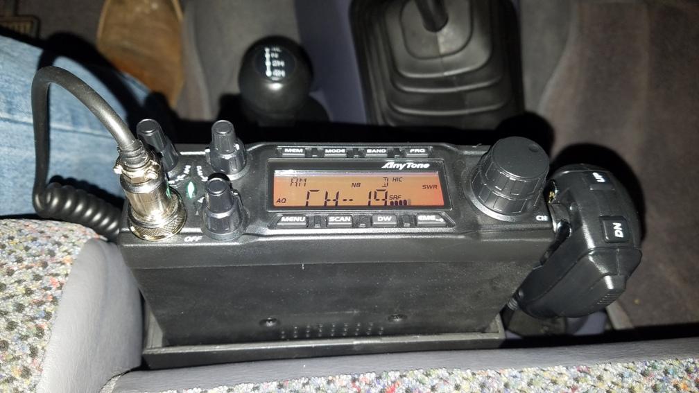
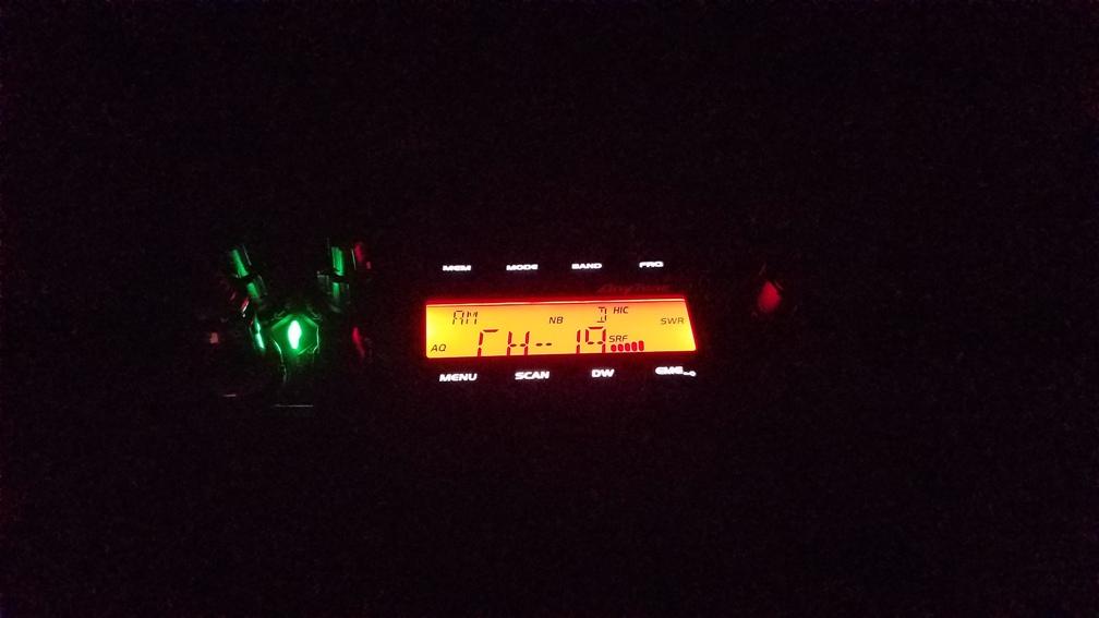
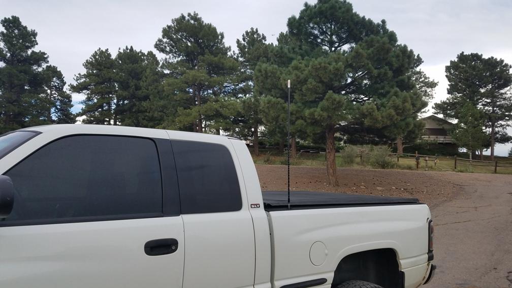
I don't do much on the forums anymore, but I thought somebody might benefit from documenting what I consider a proper radio installation for a 2nd generation Ram. Honestly it will probably be almost identical for any extended cab Ram. I purposely built this using materials anybody can get from the big box stores and truck stop radio supplies. Materials List: Qty 1: 3/4 in. x 36 in. Plain Steel Square Tube with 1/16 in. Thick Qty 1: 1 in. x 36 in. Plain Steel Flat Bar with 1/8 in. Thick Qty 1: 2 in. x 36 in. Plain Steel Flat Bar with 1/8 in. Thick Qty 1: 6 in. x 18 in. 16-Gauge Plain Steel Sheet Metal Qty 2: M8 1.25 20mm Bolt Qty 2: M8 1.25 Nut Qty 2: M8 Flat Washer Qty 2: 5/16 x 3/4" Bolt Qty 1: Wilson 305-830 18' Belden Coax Cable with PL-259/FME Connectors Qty 1: TruckSpec TS-101ADLN Thin Double Groove Mirror Mount with SO-239 Stud Connector Qty 1: 1/4" Split wire loom Qty 1: 3/8" Rubber Insulated Metal Clamp Qty 1: 6" Zip Tie (yes only one) Qty 1: #8 x 3/4" Phillips Washer HD Tapping Screw Balkamp 665-2837 Qty 1: FireStik K-1A Push-n-Twist quick disconnect (this is required) Starting with the antenna: 3' Firestik II Looking down the stake pocket: What the antenna mount looks like. You will be tempted to buy the larger four bolt mount. Don't as you can not get it in the pocket. Even this little guy takes some fiddling to get it down there. In the item list are two 5/6" bolts. This is part of the trick getting everything to fit. Separate the clamp, then you have to tap the antenna side holes to accept the 5/16" bolt. This serves two purposes. 1. You have zero chance of getting a nut on a bolt inside the stake pocket. 2. It reduces the possibility of hardware physically interfering with the coax. Things are tight in there. To make this work you have to assemble the now threaded mount, the firestik quick connect and the coax in one shot. Anything that has to be tightened to the mount must be done so prior to dropping it into the stake pocket. Here comes the painful part. Drilling holes. These are the very first holes I have ever drilled in this truck. Antennas are about the only reason I will punch a hole in a vehicle. Per the picture you can see I used the outer clamp from the bracket. This serves a couple purposes. 1. Expands the clamping area to provide better support for the mast and reducing the possibility of metal fatigue. If you don't have a bed liner grounding will also be improved. 2. It acts as a spacer to keeping the bolt protrusion to a minimum. Use a step drill bit anytime you are drilling sheet metal. Much cleaner holes. The holes are over sized in the bed to provide adjust-ability to aid vertical antenna placement. Drill the top hole first. Attach the bolt and clamp on the inside of the bed. Use that to locate where the bottom hole should be located. Then drill the bottom hole. Now we have to think about coax routing. You will be tempted to route the coax through the oval opening to the outside of the bed. This could be done, but I don't recommend it. At least not using the coax I identified in the material list. It is good coax, and has a really good strain relief boot for the antenna end. It doesn't want to make that initial turn easily. You might consider a 90 degree connector except you can not get the coax, connector and the mount installed and slid into the pocket. My solution? Another hole... and you already know I don't take that lightly. BUT... there is one upside. If you set your mount at the same height or even a little lower as I did that heavy duty boot on the coax slides right into that hole. You will also notice some discoloration around the bottom of the stake pocket. That is a white paint marker. Every hole gets deburred and paint applied. I got to the bottom of that stake pocket blind since I'm not a contortionist and have a fat head. The end result is a nice straight coax run. So I'm up to three holes so far. What's one more between friends... Cables should be secure. If left to flop around at best they break. At worst (in my opinion) they chafe on body structures eventually removing paint and then promoting corrosion. Drill a hole for the cable clamp. Secure with a nice #8 body screw. That is the last hole for this project. (I lied, there are two more) Picture shows the transission from the bed to the cab. Nice gentle loops were made. The split loom stays static allowing the coax to move within it, but the coax will not be moving. Pic at the very back of the cab. Route coax through support structure. Add split loom Picture of the coax routed through the very front cab support brace before it makes a turn to head up towards the entry point in the A pillar. Add a zip tie to the emergency brake cable. Picture of the coax exiting the front support brace and making the turn up towards the entry in the A pillar. Single piece of split loom is used here all the way up to the entry point. Trying to get a good shot of where it enters the cab is challenging. But there is a body plug below the the main door wire harness. The plug can be easily accessed by removing the interior kick panel cover. Highly recommend using a 5/16" hollow punch to make the hole in the body plug. This makes a clean tight hole for the coax to run through. Picture of the coax finally making its way into the cab. Not pictured, but add split loom where it will be pressed against the notch in the sheet metal. I added it until it met the carpet. makes it look a little more factory. From there route the coax to the interior side of the emergency brake cable under the carpet. Continue keeping the coax to the interior side of the factory wire loom. Pictured is where the coax runs back to about the center of the front seat and makes its turn for the center of the truck. Picture of coax exiting under the drivers seat with the factory wiring, and my sub-woofer speaker wire. Finally here is the end of the run. Run the wire under the center section of the drivers side seat frame then you are ready to terminate on the radio. Routing the coax this way eliminated sharp bends. It is secure. Best of all it uses all 18' of coax. No excess coils tucked away somewhere. So at this point you saw a glimpse of the radio mount. Here is a better shot. Unfortunately I misplaced the pictures of the mount before it was installed. Here is a shot from the passenger side. On both seat mounts there are two holes in the inboard rails. On my passenger seat there is an existing bar tying the inboard and outboard rails together. I utilized the factory hardware to attach the 1" vertical flat bar. I removed that cross bar so I could use a transfer punch to get the hole locations in the 1" flat bar. You could just as easily hold the bar in place and mark from the rear with a sharpie. Now onto the radio mount plate. This is also where customization occurs depending on personal preferences radios, etc. My design allows for this. You will notice I used three bolts to secure the 16ga sheet metal. The idea is most anybody I know whom is into radios change them out frequently. Using a mechanical fastner here allows different plates to be made for any radio or preference. The plate can even remain with the radio since the bolts are spaced one inch from the edge and one in the center. No trial fitments for new plates. Radio mount bracket. You might be tempted to try and bend the flat bar to the desired dimensions. Unless you do that for a living don't even try it. Using the 2" flat bar I cut the tabs to the desired height, and the base to the desired width. I drilled the tab mount holes. Then I silver soldered them together. Yeah everything you see that doesn't have a visible fastener was silver soldered. It was kind of fun going that route. Don't like how a tab sits? Made a bad measurement? Little bit of heat and you take it off and make another. Something not quite straight, or maybe you want to angle the radio more than you thought. Little heat, and re-position. I have access to MIG and TIG, and can tell you silver soldering is a pretty good route to fabricate with. So the bracket is all 2" flat bar. That gets built as a unit. then I silver soldered that to the 16ga sheet metal. I placed a small bend in the sheet metal where they join. I did this to place the radio within easy reach (my hand almost falls right on it). It also improves the readability of the display. I debate on if I put enough angle on it, but I will probably leave it as is. For the grand finale? I mounted a remote speaker under the passenger seat. I cut a section of the 3/4" square tube long enough to match the speaker mount. The tube fits inside the brace U channel providing a square surface for the speaker mount to attach to. I decided to attach the square tube with 1/8" steel pop rivets. Drill the brace from the rear in order to hit the center of the rib. In the picture you can tell the right rivet head was peened. In the end both were peened and then painted. I wanted a smooth fastener so passengers couldn't catch a finger on a screw or bolt head. Well maybe a few more parting shots. 73 Everybody.
- 1 review
-
-

-

- 6
-
-
Thanks guys. 73 is generally considered Ham, and not continent specific. I think the CB world may be a little drab from it's hayday. Ham however is pretty active. I just thought I would show what could be done fairly easily without all dime laying TIG shots. The radio could be anything including private band. With that mount setup I will add a second 2 meter radio, and a second antenna for that band. I really like the idea being able to swap a radio out in minutes, and not having some janky setup that doesn't keep the hardware secure and accessible. As for the truck. I admit it is pretty clean. Hard to believe it has over 250k miles on it. I keep it clean. After a snow storm or even a rain storm (live on dirt road) it gets pressure washed using wands with tips I can rotate to get underneath more easily. The screws for sill plates get sealed from the bottom after every removal. Absolutely. Place ii anywhere you think is the most suitable. I'm not posting it on any other forum. You and a lot of guys over here have been very helpful over the years so I made the decision that I wanted to give something back ;-) Absolutely. Place it anywhere you think is appropriate. You and quite a few other guys that are now on this forum have been and continue to be very helpful to the community. As such I have no intention of posting it anywhere else ;-) Thanks for everything!
-
So the rocker seized breaking the cup off the push rod? Not something I've seen before. The missing piece is probably on top of the head buried under oil. Or hopefully made it to the pan and not hanging around the cam. I would think it left the pushrod with some energy so hopefully it is on top of the head.
-
I don't do much on the forums anymore, but I thought somebody might benefit from documenting what I consider a proper radio installation for a 2nd generation Ram. Honestly it will probably be almost identical for any extended cab Ram. I purposely built this using materials anybody can get from the big box stores and truck stop radio supplies. Materials List: Qty 1: 3/4 in. x 36 in. Plain Steel Square Tube with 1/16 in. Thick Qty 1: 1 in. x 36 in. Plain Steel Flat Bar with 1/8 in. Thick Qty 1: 2 in. x 36 in. Plain Steel Flat Bar with 1/8 in. Thick Qty 1: 6 in. x 18 in. 16-Gauge Plain Steel Sheet Metal Qty 2: M8 1.25 20mm Bolt Qty 2: M8 1.25 Nut Qty 2: M8 Flat Washer Qty 2: 5/16 x 3/4" Bolt Qty 1: Wilson 305-830 18' Belden Coax Cable with PL-259/FME Connectors Qty 1: TruckSpec TS-101ADLN Thin Double Groove Mirror Mount with SO-239 Stud Connector Qty 1: 1/4" Split wire loom Qty 1: 3/8" Rubber Insulated Metal Clamp Qty 1: 6" Zip Tie (yes only one) Qty 1: #8 x 3/4" Phillips Washer HD Tapping Screw Balkamp 665-2837 Qty 1: FireStik K-1A Push-n-Twist quick disconnect (this is required) Starting with the antenna: 3' Firestik II Looking down the stake pocket: What the antenna mount looks like. You will be tempted to buy the larger four bolt mount. Don't as you can not get it in the pocket. Even this little guy takes some fiddling to get it down there. In the item list are two 5/6" bolts. This is part of the trick getting everything to fit. Separate the clamp, then you have to tap the antenna side holes to accept the 5/16" bolt. This serves two purposes. 1. You have zero chance of getting a nut on a bolt inside the stake pocket. 2. It reduces the possibility of hardware physically interfering with the coax. Things are tight in there. To make this work you have to assemble the now threaded mount, the firestik quick connect and the coax in one shot. Anything that has to be tightened to the mount must be done so prior to dropping it into the stake pocket. Here comes the painful part. Drilling holes. These are the very first holes I have ever drilled in this truck. Antennas are about the only reason I will punch a hole in a vehicle. Per the picture you can see I used the outer clamp from the bracket. This serves a couple purposes. 1. Expands the clamping area to provide better support for the mast and reducing the possibility of metal fatigue. If you don't have a bed liner grounding will also be improved. 2. It acts as a spacer to keeping the bolt protrusion to a minimum. Use a step drill bit anytime you are drilling sheet metal. Much cleaner holes. The holes are over sized in the bed to provide adjust-ability to aid vertical antenna placement. Drill the top hole first. Attach the bolt and clamp on the inside of the bed. Use that to locate where the bottom hole should be located. Then drill the bottom hole. Now we have to think about coax routing. You will be tempted to route the coax through the oval opening to the outside of the bed. This could be done, but I don't recommend it. At least not using the coax I identified in the material list. It is good coax, and has a really good strain relief boot for the antenna end. It doesn't want to make that initial turn easily. You might consider a 90 degree connector except you can not get the coax, connector and the mount installed and slid into the pocket. My solution? Another hole... and you already know I don't take that lightly. BUT... there is one upside. If you set your mount at the same height or even a little lower as I did that heavy duty boot on the coax slides right into that hole. You will also notice some discoloration around the bottom of the stake pocket. That is a white paint marker. Every hole gets deburred and paint applied. I got to the bottom of that stake pocket blind since I'm not a contortionist and have a fat head. The end result is a nice straight coax run. So I'm up to three holes so far. What's one more between friends... Cables should be secure. If left to flop around at best they break. At worst (in my opinion) they chafe on body structures eventually removing paint and then promoting corrosion. Drill a hole for the cable clamp. Secure with a nice #8 body screw. That is the last hole for this project. (I lied, there are two more) Picture shows the transission from the bed to the cab. Nice gentle loops were made. The split loom stays static allowing the coax to move within it, but the coax will not be moving. Pic at the very back of the cab. Route coax through support structure. Add split loom Picture of the coax routed through the very front cab support brace before it makes a turn to head up towards the entry point in the A pillar. Add a zip tie to the emergency brake cable. Picture of the coax exiting the front support brace and making the turn up towards the entry in the A pillar. Single piece of split loom is used here all the way up to the entry point. Trying to get a good shot of where it enters the cab is challenging. But there is a body plug below the the main door wire harness. The plug can be easily accessed by removing the interior kick panel cover. Highly recommend using a 5/16" hollow punch to make the hole in the body plug. This makes a clean tight hole for the coax to run through. Picture of the coax finally making its way into the cab. Not pictured, but add split loom where it will be pressed against the notch in the sheet metal. I added it until it met the carpet. makes it look a little more factory. From there route the coax to the interior side of the emergency brake cable under the carpet. Continue keeping the coax to the interior side of the factory wire loom. Pictured is where the coax runs back to about the center of the front seat and makes its turn for the center of the truck. Picture of coax exiting under the drivers seat with the factory wiring, and my sub-woofer speaker wire. Finally here is the end of the run. Run the wire under the center section of the drivers side seat frame then you are ready to terminate on the radio. Routing the coax this way eliminated sharp bends. It is secure. Best of all it uses all 18' of coax. No excess coils tucked away somewhere. So at this point you saw a glimpse of the radio mount. Here is a better shot. Unfortunately I misplaced the pictures of the mount before it was installed. Here is a shot from the passenger side. On both seat mounts there are two holes in the inboard rails. On my passenger seat there is an existing bar tying the inboard and outboard rails together. I utilized the factory hardware to attach the 1" vertical flat bar. I removed that cross bar so I could use a transfer punch to get the hole locations in the 1" flat bar. You could just as easily hold the bar in place and mark from the rear with a sharpie. Now onto the radio mount plate. This is also where customization occurs depending on personal preferences radios, etc. My design allows for this. You will notice I used three bolts to secure the 16ga sheet metal. The idea is most anybody I know whom is into radios change them out frequently. Using a mechanical fastner here allows different plates to be made for any radio or preference. The plate can even remain with the radio since the bolts are spaced one inch from the edge and one in the center. No trial fitments for new plates. Radio mount bracket. You might be tempted to try and bend the flat bar to the desired dimensions. Unless you do that for a living don't even try it. Using the 2" flat bar I cut the tabs to the desired height, and the base to the desired width. I drilled the tab mount holes. Then I silver soldered them together. Yeah everything you see that doesn't have a visible fastener was silver soldered. It was kind of fun going that route. Don't like how a tab sits? Made a bad measurement? Little bit of heat and you take it off and make another. Something not quite straight, or maybe you want to angle the radio more than you thought. Little heat, and re-position. I have access to MIG and TIG, and can tell you silver soldering is a pretty good route to fabricate with. So the bracket is all 2" flat bar. That gets built as a unit. then I silver soldered that to the 16ga sheet metal. I placed a small bend in the sheet metal where they join. I did this to place the radio within easy reach (my hand almost falls right on it). It also improves the readability of the display. I debate on if I put enough angle on it, but I will probably leave it as is. For the grand finale? I mounted a remote speaker under the passenger seat. I cut a section of the 3/4" square tube long enough to match the speaker mount. The tube fits inside the brace U channel providing a square surface for the speaker mount to attach to. I decided to attach the square tube with 1/8" steel pop rivets. Drill the brace from the rear in order to hit the center of the rib. In the picture you can tell the right rivet head was peened. In the end both were peened and then painted. I wanted a smooth fastener so passengers couldn't catch a finger on a screw or bolt head. Well maybe a few more parting shots. 73 Everybody.


-
Like many others have said it. LED's have no place in any housing that was not designed for them. Might look excellent from the driver seat, but oncoming traffic will say otherwise. Listed in order of cost and simplicity. Polish the housing if it cloudy. Install relays and heavier gauge wire to minimize resistance providing full current capability with the side benefit of taking the load off the switch. Install sport headlight housings... not the cheap ebay stuff either. OEM Projectors... I'm hesitant to recommend that. Installation and quality components is everything. It is far from plug and play. GE 9007 NHX/BP2 Nighthawk Xenon are excellent bulbs. Better than Silverstars. I have never seen them in a parts store. Sit down before you price shop. In addition high performance bulbs have a considerably shorter lifespan. GE NIGHTHAWK PLATINUM 9004 are my high beam goto bulbs. Also never seen them in a parts store.
-
Thanks guys. I noticed the app hanging during export. I never worried about it because I figured it was related to file size or other processes running trying to get the export out. I just wait it out, and let it do it's thing and it eventually completes. I like the fact loging starts with key on. Trying to figure out a hot idle skip. If I remove the Adrenaline it goes away. Injectors make no difference. CAN fueling seems to be busy making adjustments at idle but I don't know how/if that is related in any way. My gut is hinting at injection pump. Otherwise I like the improved tuning capabilities. Light years ahead of what was originally released with the Adrenaline.
-
Quick data logging questions that I don't recall being answered. 1. What is the log maximum? Time 3.5 hours? File Size? Maximum # of log entries? 2. What happens when the maximum is reached? Overwrite oldest first? Hard stop? 3. What starts data logging? Always running? Manually selecting data logging? I want to crunch some of this data. Want to make sure I understand how big the playground is. Might try tossing it into Splunk.
-
Over all there is really nothing wrong with how it is operating. However you're skipping over the coolant smell. If you are not seeing any visible signs of coolant loss, yet keep smelling coolant your heater core is highly suspect. They typically start as a really slow seep. Just enough to smell, with some slight hazing of the windshield in front of the defrost vents over a long period of time. The system is self bleeding and may take a while to finish. If there are air pockets in the system you will probably hear the bubbles running through the heater core. It will sound like a little water fountain in your dash.