
W-T
Yearly Subscription
-
Joined
-
Last visited
Everything posted by W-T
-
Try taking the Quadzilla off line and perform a test, the idle issue must be corrected prior to moving forward. I can't imagine you loosing the ECU in these simple procedures.
-
OK... Avoid taking Pin #5 (Drk Blu/White trace) to ground...that is 5Volts dc...it will be a big issue. An Additional Parallel ground won't hurt in that regard. Your background looks good...wouldn't you just love to grab the guy by the throat who performed such previous work..golly it's messy!
-
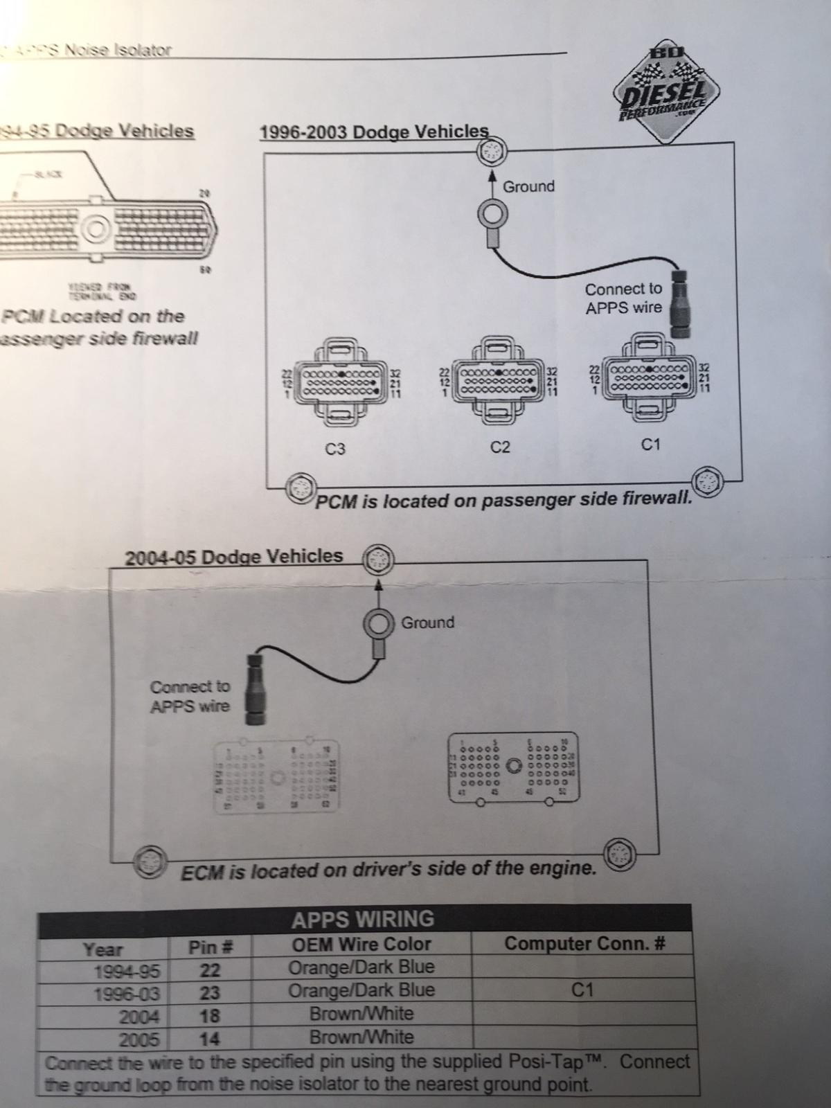
OK...The APPS plug has 6 total connections. It's numbered funny and if you have the Factory Service manual or access to a wire/diagram it would help. Pin #1 is the shared master ground for many sensors and terminates at Pin #11 of the ECU it should be BLK/ Lite Blu trace Pin #6 is Idle Validation "OFF" and terminates at Pin #01 of the ECU it should be BRN/ORG trace Pin #2 is Idle Validation "ON" and terminates at Pin #16 of the ECU it should be BRN/Dark Blu Pin #4 is APPS Return and terminates at Pin #32 of the ECU it should be BLK/Yellow trace Pin # 3 is APPS Signal and terminates at Pin #25 of the ECU it should be Lite BLU/BLK trace Pin #5 is +5V dc and terminates at Pin #31 of the ECU it should be Dark Blu/White trace I'm viewing a PDF file as my Factory Service manual is not available to me. Your reference of BLK/Blu tagged to ground is confusing me. I know you removed it but, I don't wish to cause you additional stress.
-
Gosh...the previous work done prior to your effort is what I'm concerned about. The idle climbing to 2k and hanging is an issue. Prior to performing any changes did you see this idle issue?
-
I too agree with much of what has been posted here however; fee wise, this site being what it is requires .27 cents per day. That's nothing compared to much of the necessities we all pony-up for our daily lives. Heck, I spent $3 on beer just yesterday and that's a total of $1095 per year! @LorenSright, many talented individuals are missing in action but, occasionally they do pop up on this site when subject matter has merit and the skill set of the individual is warranted. They all know, as do we, their contribution is always of interest. TDR is the big player and I was a quiet member back in 2001 when I first joined up. Being this was my first diesel rig, I wished to glean knowledge and the control aspects were just being pioneered most notably by Marco in Italy, playing with ECU's and the initial development of the Smarty's. I found it to be an excellent starting point. Yeah...TDR has a massive presence however; when it comes to real nuts-and-bolts of the 2nd Gen's, Mike Nelson blew them away. It's easy to see when you page through a few of the other sites and observe the buffoonery...who can roll-coal to put the lights out or the infamous "tin foil hat brigrade" looking to solve electronic faux-pas issues. Truly, M1973M has merit and general qualities for the discriminating and practically-minded Diesel enthusiast. Further more, seriously... the 2nd Gen platform is the "Cult status" platform! Yeah, I know there are lots of guys with 3rd, 4th and 5th Gen rigs that have modern notable advancements but, why is it when I'm out and about with my 2nd Gen that invariably one of the aforementioned platform owners offers to "swap" trucks with me? Yep, I just laugh it off and tease them with it, "Sucks to be you". I'll never relinquish this rig...she's pretty compared to the bulbous-fat looking later models and as Nelson and other knowledgeable individuals know...working on a 2nd Gen is a pleasure. Re-Gen...what the hell is that?, oh gosh, don't forget the Blue DEF crap...boy am I glad I don't have to deal with that. Let this site remain FOCUSED...dump the silly herbal medicine (stone-able) $hit and get back to business. Pay attention to the technical functionality of the site and 27 cents a day is not too much to pay for what this site has brought in the realm of notable technical excellence. As time progresses, all vehicular platforms that are worthy, eventually become the most desirable in regard to nobility...the same goes for web-site nobility. @KATOOM, @Haggar, @pepsi71ocean just to mention a few, are always interesting contributors and lately, observing the banter between @wil440 and @Tractorman has been quite enlightening and I find it intellectually stimulating. Why is there a lull in activity? Gosh, let me guess...the political garbage of the present regime in power? What bathroom does your kid need to use at school, what anti-American organization wants to burn your city offices to the ground, what minority is offended by the vehicle you drive? Damn it! there is so much crap going on, I believe the average individual is depressed to the point of mindless mediocrity. It's a nation wide and world wide sickness that's overtaken the hearts and minds of so many people and we've lost the sense of enjoyable fun. Let's hold on guys and gals...we are just a bunch of blue-collar-butt-cracks enjoying what "we" find of interest and it's that mutual interest and respect that allows longevity in the pursuit of happiness. In time, perhaps membership will grow and yearly fees might subside however; let's not forget what we do have on this site compared to the "other" sites. I should apologize for my caffeine fueled rant...I don't know what has taken me over this morning but, for all the terrible things that have come our way in the last 16 months, let's try and support what little joy each of us can eek-out for another day. BTW...sure miss @dripley Respectfully W-T
-
Mr MacKenzie...Wow, what a blast from the past, good to see you...welcome aboard.
-
Yeah...well I found this photo of Nelson coming out of the room where he keeps the server and it appears the "wee turtles" were the issue for all of us. Geeze...what a mess!

-
@Max TuneI too was skeptical however; in review I found some of the YouTube short videos depicting the operation of these devices with caged critters reacting in very uncomfortable reactions once the devices were triggered into operation to be quite revealing. The package has warnings of not to torment domestic pets by exposing them to long term exposure. @LorenSI should clarify that these devices have a vibration-control so, when you power up your given vehicle the device(s) shut down and remain dormant during vehicle operation. Once you arrive at a given destination the internal timer will begin the operational sequence at approximately ten minuets of "still time". The operation is NOT constant, it actually goes on and off in a preprogrammed sequence to cause an uncertainty in it's operation to alleviate the animals from becoming accustomed to the annoyance. Also, I too, strongly rely on BatteryMINDer product and design. I eliminated the Fred Flintstone wet-cells shortly after purchase of this CTD to avoid the long term effect of sulfuric acid pheromones destroying the electronic aspects of this vehicle. Under-hood conditions are poor without volatile gasses being a continuous volatility that leads to uncertainty in the long term. I achieved 16 years of flawless service from my first pair of AGM's religiously utilizing BatteryMINDer disciplines and carefully engineered platinum coated battery connectors to insure current flow integrity. Owning this CTD has been a pleasure and I believe conscientious forethought for longevity has paid off. W-T
-
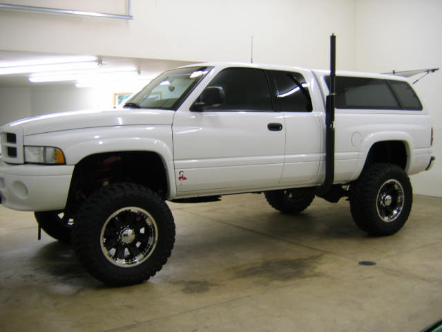
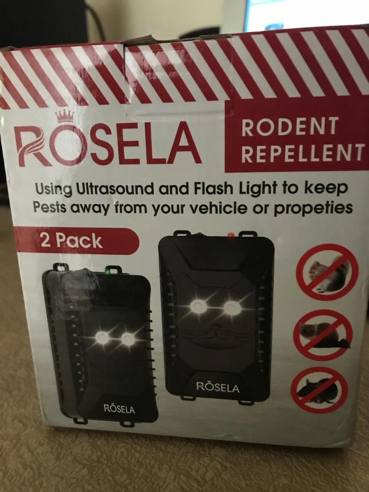
@LorenSsorry to know of what has transpired under the hood. I lost my garage and have been storing my CTD undercover at the west side of my home. I too noted the issues with rodent wild life but, not to the extent of your situation. I elected to use electronic Ultra Sound with random flashing high intensity LED's This is very inexpensive and arrives with two devices in a single package. The current draw is very low as I elected to tie them both directly to 12 Volts DC and my BatteryMINDer provides pulse-width float for my AGM's The threshold of charge demand or extraneous parasitic current demand from both of these devices does NOT trigger the BatteryMINDer when they operate to emit Ultrasonic audio and flashing LED's in the sequential staggered order. Each unit sinks no more than 35 milliamps. I mounted both small packages to the side of each battery so the LED's distribute light from opposite sides of the engine compartment. They both have miniature power switches to allow powering each one up with a 30 second delay between each unit to allow for separate sequential operation between the two units. These devices will allow various DC supply levels 5 to 16 Volts or 4 AA batteries to operate. The package arrives with the various DC miniature cables and zip-ties to quickly provide operation. All, wild life daytime and nocturnal avoid my truck like a plague...it has been extremely effective. No smelly chemicals or doping required. W-T
-
Truly fascinating, I'm impressed and wish I could join in with this research.
-
@Andyba20 The nature of an electrolytic capacitor in the aspect of "uF" or micro Farads level (capacitance) acts slowly in reference to the supplied DC line level. If we have a 5 volt DC rail supplying a variable resistor, which is what we encounter with the APPS device and we change the position of the variable resistor when manipulating the throttle as we drive, the DC voltage changes, which causes the amount of current (milliamps) to vary within the circuit. The misconception of using an electrolytic device in "parallel" with this "variable resistor" as an intended filter for extraneous noise on this purely DC reference line upsets the DC time constant of the APPS device. The true nature of an electrolytic capacitor is to "store an electric charge" much like a regular battery holds a charge for an extended period of time. The purpose of the APPS is to allow a "quick" change in throttle to be calculated by the companion circuits following or tracking this change. The electrolytic capacitor will charge to a peak level of the supplied DC voltage and remain at the present DC level being provided. Examining the electrolytic cap specifies maximum DC levels from a voltage standpoint and capacitance level in micro-farads. If you introduce an electrolytic cap in this circuit it immediately charges to a given level of DC above ground. This upsets the actual DC level we attempt to set in the calibration procedure of a factory OEM APPS device because the electrolytic capacitance is slow to discharge the initial "bump charge" it was initially charged to. In practice as we drive down the road, a driver will attempt to hold a consistent speed, on occasion a driver will back off the throttle to slow down according to road conditions or any other reasonable purpose the driver deems necessary. This electrolytic in parallel with our foot causes a delay or increased time constant to be in play. It introduces a "sluggish" or delayed response from our variable resistor (APPS device) because even though you let off the loud-peddle the slow discharge of the electrolytic is still commanding the VP44 to fuel. An electrolytic capacitor will appose a change in voltage...as you go down the road at 2 volts and you back off...the capacitor will begin to discharge its self in an attempt to maintain the DC level it had prior to you holding that variable resistor at a desired level. It fights your "let off" by many micro seconds. Our APPS system has two DC operations or settings. The first is IVS (Idle Validation Setting) where the static setting for low RPM engine operation is achieved. Mike's @Mopar1973Manarticle regarding this setting is very enlightening and I must mention Timbo's aftermarket APPS simplifies much of this due to a brilliant design aspect. Careful review of what Mike Nelson has presented in the APPS article is excellent foundational knowledge. This poorly thought out "band-aid" fix as a "big fat slow filter" is not the way to do this. The frequency of "fuzz" on the 5 Volt DC rail, most likely being induced by poor ripple effects of a given alternator's rectification process along with poor continuity at critical ground points is a "fast fuzzy" mess and can be served well by perhaps as little as .5 uF or less as a bulk DC filter in regard to cleaning up "poop" on our 5 Volt DC rail. I'm sorry to have never scoped-out the general noise aspects on critical 5 Volt DC rails under the hood of our 5.9 CTD's , perhaps someday I'll have a chance to examine the "dirty fuzz" and provide incite to further harden the excellence of these cult vehicles. My apologies for this most concise dissertation to answer an excellent question from @Andyba20and I shall refrain from going down the rabbit-hole in explanation of uF/resistance time constant in practiced DC theory....though you know I'd like too but, I need to prepare an evening meal and grab a cold beer. Cheers, W-T
-
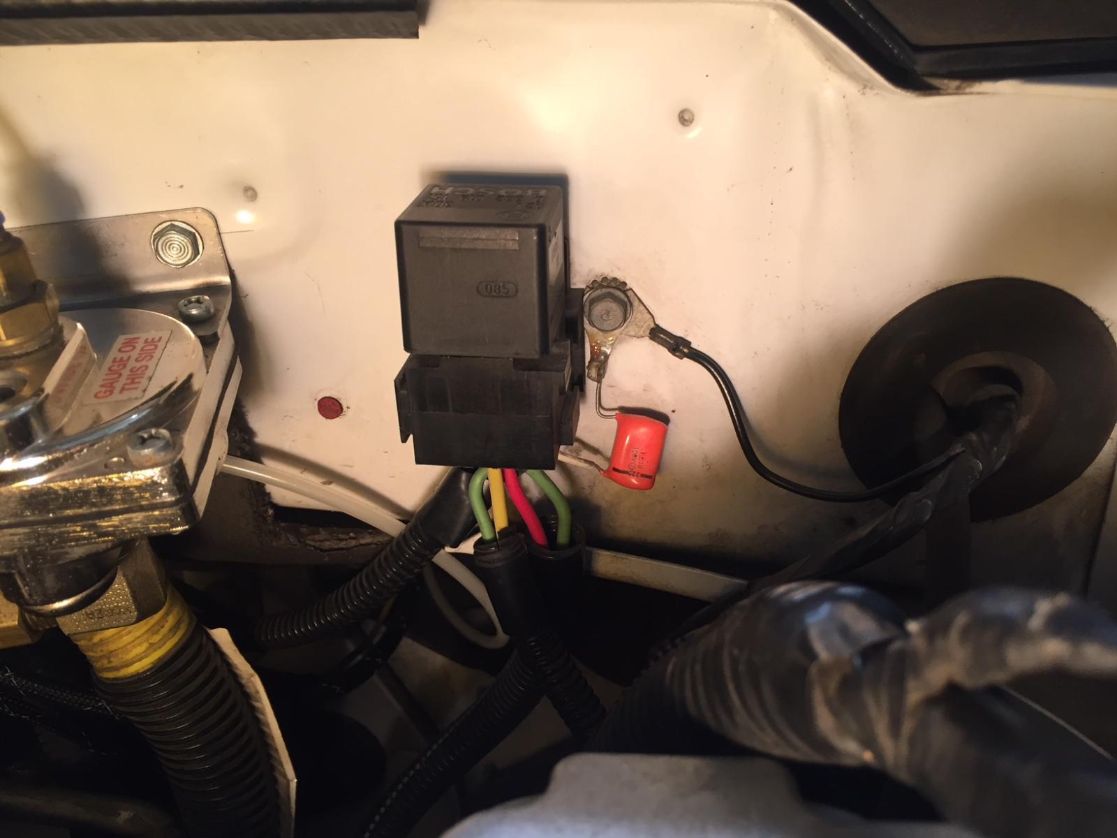
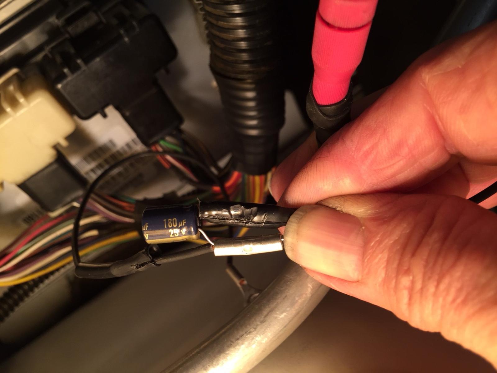
If this truck was purchased used, I suggest you review the connections at the PCM to locate a troublesome modification that a previous owner may have applied. Connector C1 (far right connector) Pin #23, Orange/dark Blue stripe is the APPS line. If you find this "black heat-shrink" blob tacked or spliced into this line with a short jumper wire to the firewall ground, remove it. This is an error repair/modification from BD Diesel that causes many errors. It's a cheap 180uF electrolytic capacitor that is mistakenly being used as a "filter" to swamp noise on the APPS line. If you find anything connected to this line it is a grievous error. The improper analysis by BD's engineering staff has been marketing this little black box booger for many years and it causes many problems. BTW...the capacitor is 35 cents, the "wire tap pinch device" is 65 cents and the "shrink tubing" to hide this mess is less than one penny. This "magic" filter sells for $30 via BD's website. If you do find this black-blob error device and you gracefully remove it, follow up by re-calibrating the APPS device at the bell-crank. Cheers, W-T
-
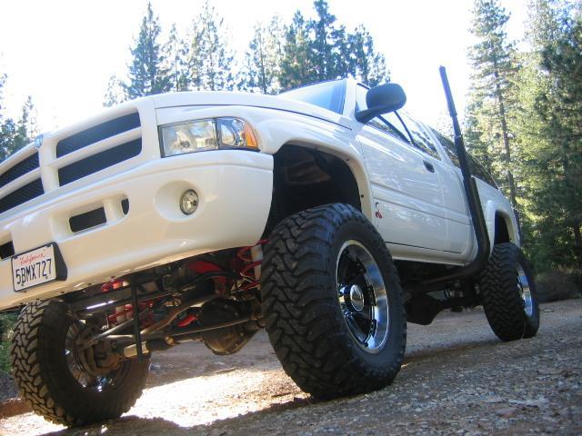
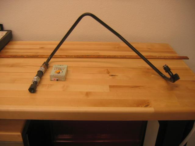
@SpdfrkYes, the configuration is a low frequency mount for Amateur Radio. I do not cross over into electronic communication wizardry on this site. It's merely another facet of interest accomplished with insanity but, it pairs well with 2nd Gen diesels due to the fact that our platforms are completely quiet RF wise. There is NO motor noise to compromise weak signal radio communications. You will find some real accomplished Gurus on this site. @Mopar1973Man is the proprietor and his contributions going back 20 years is what attracted me to this site. The administration of this site is undoubtedly the most helpful regarding the diesel enthusiast. If you find subject matter from the historical past and you wish to reiterate or clarify the subject, please do so. Everyone here will be compelled to jump into the fray to provide answers. Again...your truck is exceptionally bitchen...it is a real gem!
-
Welcome to the forum, Wow... I like your style but, I think I might be biased! .
-
Dan @IBMobilenice procedure to prevent debris entering the cavity...the job of removing the core for clean up is miserable job and your example really promotes clean longevity. @JAG1...Mike, I'm not that bad...or am I ? OK, perhaps I'm a bit excessive but, my Mom had me tested and the Doctor did confirm an Excessive Compulsive disorder and advised keeping an eye on me.
-
This is one sad situation! I'm only guessing in regard to the issues @Myvp44hatesmehas encountered however; your DC voltage is most likely NOT an issue for you. Excessive AC ripple from your alternator being imposed on the 12 volt rail and sub-managed 5 volt rails wouldn't manifest itself to cause this mountain of errors. Not to appear stupidly redundant and add insult to injury... BD Diesel are complete morons regarding electronics. They have been responsible for causing numerous electronic errors for over 20 years. Seeing the relationship they developed here is another reason to avoid them. I'm sorry for your loss in time and funds.
-
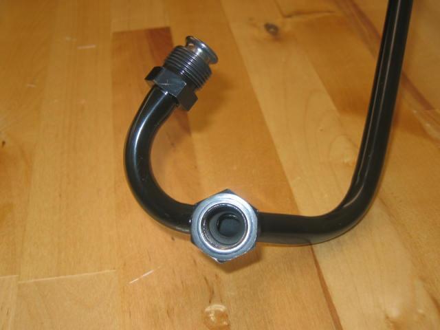
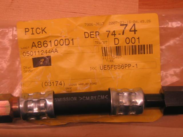
I too had a misconception regarding the reason for the heat exchanger shortly after purchasing this 2nd Gen in 2001. I proceeded to build my A-pillar gage cluster with Boost, EGT and Transmission temperature however; I didn't have an aftermarket transmission pan with a temperature sensor probe to allow data for the temp gage. I really don't know what I was thinking at the time and I went to Dodge to ask what they suggest to obtain readings in regard to transmission fluid temperatures. This optional "Hot" line output from the transmission was available directly from Dodge and included the "vibration" coupling hose that couples to the Heat Exchanger. I thought this was the proper way to extract transmission fluid temperature data for my gage cluster and keep it OE as an additional or optional accessory according to Dodge. Wow, I was not thinking correctly! This assembly was extremely expensive ($225) and hind site reveals I could have purchased a quality deep pan with the in-pan temperature port from Goerend for less money. Now, I was reading thermal fluid temperatures directly, after all the thermal stress aspects, have been transferred to the fluid. At warm up conditions on a 95F day I was observing 220F ! I wasn't pleased with my decision to have incorporated this optional "Factory" assembly. The fascination with this "hot" line output was the extremely convenient port assembly to allow my new Hewitt Industries temperature sensor to be applied with a clean appearance. I thought to myself, "wow this is sexy" and being so extremely anal about "how" something looks when completed...I just had to do it. I didn't fully understand why the "hot" fluid was being transported to this 'heat exchanger" and as @pepsi71ocean has presented in this thread as a historical refresher, (and I must say thank you) I too found the ability to transfer heat immediately from the "hot line output" prior to the coolant passage of the radiator to be highly efficient in design. Eventually, I was able to take temperature readings after the heat exchanger and discovered a 30 to 40 degree subtraction from the "direct hot line output" and rested my concerns. My travels to Idaho Falls, ID and Butte, Montana during the winter months does require the added benefit of the heat exchanger and @LorenS, thank you...your information regarding the lack of overdrive in frigid conditions now enlightens my understanding....honestly, after 21 years of owning this truck, I did not know that! Cheers, W-T
-
Merry Christmas to all...we all need a bit of cheer after living through this year. (let's go Brandon)
-
I obtained the metric bolt from my local ACE Hardware store and it's considered quite common. The location on the housing where you're going to place this ground connection is tapped perfectly for this metric application. I'm sorry you're having difficulties locating a source for this single bolt.
-
To provide any fuel flow in regard to a failed primary pump is a good thing. I believe this prudent method could be a real asset in a failure on the road situation. I like it John and eliminates the alternative of just sitting on the side of the road. BTW, I've followed your observations of volumetric flow and it has been quite informative. Cheers W-T
-
It's nice that Nations would provide the correct pulley as this assures the idle charge rate to correctly track via command from the PCM. I see your 13.84 volts DC to be correct with regard to healthy batteries following a "start" event and indicates proper replenishment current flow. An improper pulley would most likely produce a noticeably lower charge rate. I commend your plans to follow through in double strapping your storage cells. The added complexity is worth the cost/effort to truly isolate the "power supply" integrity and assure both cells being charged according to temperature correlation. This will allow excellent performance of the planed winch accessory and replenishment charge following its use when required. I would encourage the inspection of the alternator's mounting structure. The ground attachment is quite robust physically and each bolt is your DC ground return point hence; DC integrity dwells within this mounting assembly and requires attention in cleanliness to eliminate minute DC resistance. High current generation with poor mounting disciplines leads to electrolysis and increases DC resistance over a period of time through the cancerous action of current flow. Grease your threads and clean your holes is a good method to prevent errors for long term reliable performance. Nice work, Cheers W-T
-
Well, I'll try not to ruffle feathers but, I've been known to do so.... The original DC charge wire traveling across the top front of the entire engine bay terminated into the PDC box on the drivers side fender. I'll assume you know this and if so, then you also know about the fuse directly at the point of termination. It's a 140 Amp fuse that feeds the entire system within that box. Examining the box reveals a tremendous amount of "other" fuses that distribute DC to various points within the vehicle. Any other connection point drawing current is protected by the individual fuses. The 140 Amp fuse is worthless in that location and all other circuits are protected by their own individual fuses or circuit breakers. Allow a moment for review regarding these protective devices known as fuses or circuit breakers...they sort of work...but, not really, but, kinda-sort of function....I'm being ambiguous in a distorted way on purpose. They are there to break current flow in a catastrophic dead short to GROUND. They are there to prevent an electrical fire in regard to a vehicular accident. Any sensitive electronic device connected within the DC system of these vehicles will be subject to damage because the time it takes for a fuse to open (blow) or circuit breaker to react exceeds 20 milliseconds. Please note the single #1 gage wire connected directly to the starter motor and that wire is DIRECTLY connected to the positive terminal of the drivers side battery. NOW this is a heck of a wire! But, you'll notice it has NO fuse! The reason is because, the solenoid on the starter motor will over heat and fail to close during continuous cranking condition of the ignition switch. Any Cummins 5.9 that won't start within a very short period of time has issues and intermittent operation of the starter motor in these vehicles is just that....intermittent operation. Good, because these starters can sink more than 800 Amps in a given condition. Observing your new 180 Amp Nations alternator, the stud on the back connects directly to your passenger side battery + terminal. That alternator is commanded by the PCM and at idle (assuming your pair of batteries are healthy) the nominal charge arriving at the B+ post is minor in regard to having the Cummins spinning at 800 RPM's hence, the output of the alternator is minimal. Now, let's look at the BATTERY B+ post that's inline with this new 200 Amp protective device...in a complete act of buffoonery who would take a large wrench and touch the backside of the 200 Amp fuse to GROUND? Seriously, who would do such a thing? It's NOT the output of the alternator opening this fuse...it is the tremendous current capability of the battery itself passing current to ground and opening the fuse. Look at a 1965 Ford Falcon with an inline six cylinder engine...does it have a fuse between the alternator and the battery? How about a 1967 Plymouth GTX with a 440, or perhaps a 1969 Chevelle SS 396.... the idea is or was never incorporated due to the understanding of current flow. Daimler Chrysler was in great error placing a 140 Amp fuse on the input to the Power Distribution Center in this manor. It will not protect the alternator because the alternator must be at very high level RPM's and have a command from the PCM to excite the field within the alternator to produce maximum current in order for an external fuse to blow due to excessive current demand. Keeping in mind the amount of time to open a fuse or breaker with a potential of 140 Amps at 14.8 Volts DC which mathematically equates to over 2 kilowatts...in a fraction of a second (less than 20 milliseconds) sinking that kind of power directly to ground is going to wipe the alternator into an oblivion. Anyone telling you to place a fuse on the output of your alternator to protect your alternator is in great error. I find it comical and I've not said anything about this for years because it's just silly. I believe money can be well spent in other areas and this aspect is not one of them. However, to each is his own With Respect,
-
@Silverwolf2691yeah...I was trying to be comprehensive with a "name" for the Original article to cover a wide search regarding the covered subject matter. I have NO idea how it was slanged into W-T ground mod....I didn't do it. Truly "ground reference" should have sufficed.
-
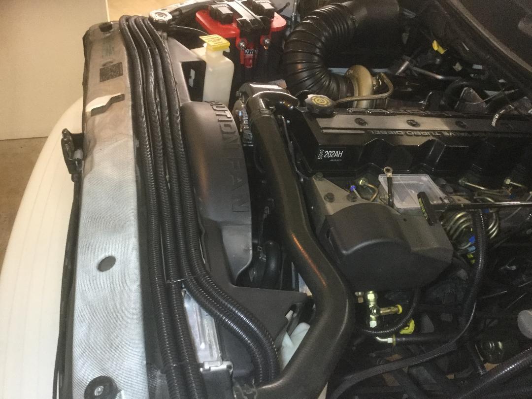
The thermistor located on the drivers side battery is providing feedback to the PCM in order to regulate the charge rate. Correctly double-strapping the storage cells assures the parallel configuration to be absolute. Do not rely on motor grounds or body grounds to provide the minimal resistive path between the two batteries. The thermistor provides thermal resistive current changes to a comparator within the PCM and these changes are tracked within a half of a degree C to maintain proper charge rates over a very wide temperature range. The original configuration had the alternator passing current to the drivers side battery first. With the W-T mod, the B+ charge is now provided to the passenger side battery. The temperature sensor is alike the thermometer placed into the baby's butt for absolute reference hence, exact parallel configuration is required to eliminate any extraneous DC resistance that will be incurred if one relies on the cheap budget minded configuration provided by OEM specifications. The mediocrity of the original factory DC layout had no regard for excellence. The upgrade to a Nations 180 Amp alternator where the B+ is now provided at the passenger side battery positive post deserves attention. Double strapping is the correct and error free method to provide equal charge between the two cells and eliminate extraneous DC resistance at extremely small levels that nullifies the accuracy of your thermistor providing absolute results to the PCM's comparator circuit. This fries batteries and undercharges in other aspects. Your winch configuration will also benefit in regard to your connection points being applied to the passenger side battery. The addition of strapping between the two cells is done with #4 gage cable and lays into the top of the radiator and air/charge cooler troughs, done correctly it looks killer. I have AGM batteries, the cost was twice, what Fred Flintstone wet cell's costs because I do not allow sulfuric acid fumes to fart all over my electronics under the hood. After 20 years this truck is flawless electronically due to the elimination of mediocrity. Budget, yeah...I understand that however; when you're chasing electronic errors that continually haunt you for years, sometimes it's just best to do it correctly the first time. I have NO comment on the additional 200 Amp fuse mentioned in the post...it was never in the Original W-T article for a reason. Cheers,
-
@McDaniel24vI have to fully agree with Dan @IBMobile in his suggestion to start fresh with this lift-pump relay harness. It's really not hard, the basic aspect is you're using the original control wires (only 2) that previously powered up the factory Carter lift-pump to provide 12 volts in order to trigger the isolation relay and provide a direct battery 12 volt source to your aftermarket lift pump. I would refrain from butt-splicing and soldier all specific wires followed with quality heat-shrink insulation at each connection. Attempt an effort to match color and wire Gage of the harness to avoid confusion. Dan's link to his protective-lift-pump relay is certainly worth the study time and provides excellent preventative anti-back EMF when the relay is de-energized once 12 volts is removed by turning your ignition to the off position. It just prevents spiking the ECM's driver circuit in shut down. Attempt to mount your slave relay to the firewall for occasional easy access...Velcro tape tabs can help in a pinch as I see by your photo's depiction, the relay is merely plugged directly into a bulk connector. Having a relay flopping around under the hood unsecured should be avoided. Additional noise silencing can be easily achieved with a .1 Mfd Mylar cap connected directly to the 12 volt supply line that feeds the lift-pump's remote location. That 12 Gage wire is nearly 9 feet in length to reach the remote lift-pump location and by shunting .1 Mfd to ground will help alleviate the armature noise of the running motor that powers the lift pump. The 12 volt connection point on the relay that provides current to the lift pump is where this capacitor is located and you merely take it to ground with as short leads as possible. This advice is basic and is NOT provided by any of the aftermarket lift pump manufacturers. Dan's instructions regarding the relay coil back-EMF diode across the coil is proper engineering for any DC actuated relay coil.