


IBMobile
Staff
-
Joined
-
Last visited
Everything posted by IBMobile
-
Yes, that's an Airtex lift pump. I have that parts store trash mounted as a back up pump to the Fuel Boss. I've used it twice to prime the fuel system. It was reliable enough for that.
-
Things like this are what makes for fun memories in the years to come. Glad you had a fun, safe trip.
-
Yes, just before the T fitting.
-
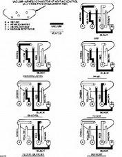
Yes it is but this picture of a V8. You find the vacuum check valve for the diesel module at the firewall top left of center, just to the right of the hydro boost. It's at the end of the vacuum line from the vacuum pump.
-
I have throttle limiters for sale. They make great Christmas gifts. They are inexpensive and easy to install. You tape it to the backside of a throttle peddle. They come in two colors, white or brown. Below is one in the brown color. You know when the throttle limit was exceeded. It will look like this. None of my throttle limiters are related to @dripley
-
Congratulations! Boys are great. But just you wait until they want to drive. You'll be a nervous wreck as you stand by watching them drive the truck out of the driveway.
-
NO, their not. They still ask if you want fries with your order.
-
I think you might have two problems. I think your ignition switch my not be fully returning to position II due to a sticking lock cylinder. The next time this happens rotate the ignition key slightly back, counterclockwise, and see if things change. Are your batteries in good condition, not to old or weak? Make sure grounds are good and battery terminals are clean, tight and in good condition. I was having high AC voltage, 0.05-0.1, and replaced the diodes and brushes. Now the AC voltage is at .03.
-
I use the factory hard line for the fuel return line to the fuel tank filler neck, You can run new hose from the tank to the filters/pump.
-
I'm wishing the best for everyone this Christmas Season. Hoping for joy, good health and prosperity now and throughout the coming year for all of you and your families.

-
Why isn't the stock filter good? I have a Fuel Boss mechanical pump and push the fuel through the stock filer/water separator housing.
-
The 4WD switch grounds pin #2 of the antilock brake controller. The 4WD indicator light is turned on at the same time by grounding the LED blub through pin # 10 in C2 at the instrument cluster. This means that there is power supplied to the various indicator lights in the instrument cluster and they are turned on by grounding them. If you ground pin # 10 and gray wire behind the instrument cluster the LED 4WD light should turn on. If the light turns on when grounded then you have an open circuit to ground IE: bad switch, poor contact in a connector or broken wire. If the light does not turn on then either a bad LED blub or no power to the blub.
.jpg.83a0888ff10c7d30c813a0996d64fc71.jpg)
-
Use two pair of needle nose vice grips with vacuum hose pushed over their jaws to clamp fuel hose and adjust to fit hose. I've used this setup on heater, fuel, brake and transmission hoses with no problems,
-
From the 2000 Dodge Ram Pickup Cummins Turbo Diesel owner's manual. #18 is the 4WD light
.jpg.7539a8929920737d1a36531dd80e1a73.jpg)
-
With a vacuum pump, can be hand pump type, apply up to 15" of vacuum to hose and watch the movement of the lever attached to the vacuum diaphragm. The vacuum applied to the diaphragm should hold for several minuets if not then there is a leak in the diaphragm. See if this will work for you.
-
I have a small crate full of hub caps but none are for a Dodge truck.
-
The variation in temperatures shown between the gauges can be attributed to the calibration differences by the manufacturers as well as cylinder fueling/combustion efficiency.
-
Don't use WD40 in the lock cylinder. It will dry out in a few days and can wash out any lube that's in there now. I spray a light lubricating oil in the lock cylinder then work the action a few times. Gun oil will work too.
-
I get out of truck, close the door, push lock button on key fob. The interior dome light shuts off, horn beeps once, doors lock. My Volvo park lights flash once when locking but no horn beep.
-
Think about this: that can, for an 8 cylinder, will treat 5-6 qtrs. of oil so you may need to use 2 cans to treat a Cummins 11 qtr. engine.
-
When do you plan on doing this? I see you live in San Diego. Del Cerro area? I'm a half hour north and can help you with this, I've dropped a few tanks over the years. I have my work van with tools, floor jack and 5 five gallon fuel containers to pump your fuel into.
-
I've use Seafoam, through a vacuum port at the intake manifold, to clean the top end of a gas engine then add a can to 1/2 tank of fuel prier to state smog inspection. This helps to lower the NOX emissions.
-
You have to ask yourself, "got new parts and the problems are fixed so why do I need to keep these bummed up parts around?" If you could "fix" them would you trust them to function correctly over the long haul?
-
That's what I do with my boat motor and 5th wheel generator otherwise the fuel can evaporate in the carburetor fuel bowl over time and leave a varnish behind that will plug up the fuel jet. The fuel in the tank is still good to go with out any fuel stabilizer.
-
I've noticed this also. I run the 91 non ethanol in all my small engines and have found then to start up with no problems even after they have sat unused for months at a time.


